Table of Contents
Advertisement
Advertisement
Table of Contents

Related Manuals for ANCEL PB100


Summary of Contents for ANCEL PB100
- Page 1 Table of Contents...
-
Page 2: Table Of Contents
Vehicle Super Probe Table of Contents 1. IMPORTANT SAFETY INFORMATION............2 2. USING THE TEST TOOL ................2 2.1 SPECIFICATIONS ................2 2.2 TOOL DESCRIPTION.................3 2.3 PARTS LIST ..................4 2.4 GENERAL DESCRIPTION ..............4 2.5 POWER ....................4 2.6 QUICK SELF-TEST ................4 2.7 AUTO CIRCUIT BREAKER ...............5 2.8 WORK MODE. -
Page 3: Important Safety Information
Vehicle Super Probe 1. Important Safety Information To prevent personal injury or damage to vehicles and/or the test tool, read this instruction manual first and observe the following safety precautions at a minimum whenever working on a vehicle: ◆ Always perform automotive testing in a safe environment. ◆... -
Page 4: Tool Description
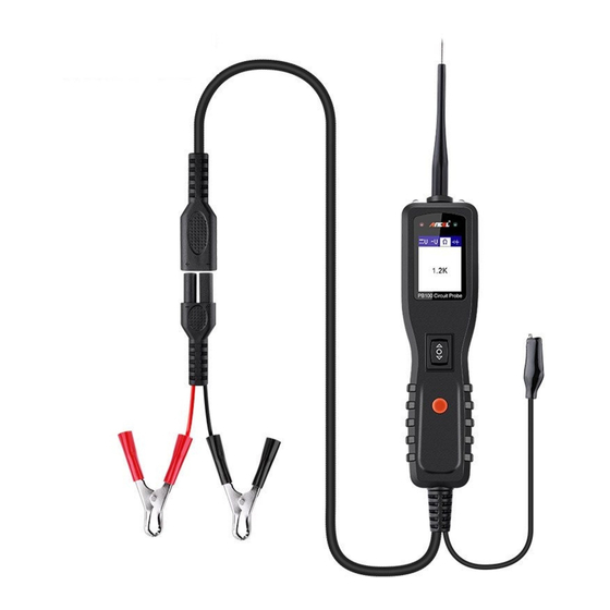
Vehicle Super Probe 2.2 Tool Description ① Probe Tip - Contacts the circuit or component to be tested. ② Head Lights - Illuminates dark work areas or work areas at night. ③ Red/ Green Polarity Indicator - Identifies positive, negative or open circuits. The RED Indicator lights when the Probe Tip is contacting a positive circuit. -
Page 5: Parts List
Vehicle Super Probe 2.3 Parts List Part Description User’s Manual Cigarette lighter adapter Battery hookup clips Probe tip Extension cable (20ft.) Rugged blow molded case Power assist cable 2.4 General Description The tool is the best electrical tester for reducing diagnostic time in all 6 to 30-volt vehicle electrical systems. -
Page 6: Auto Circuit Breaker
Vehicle Super Probe markings. Press the Power Switch forward to activate the tip with a positive voltage. The Red LED should light and LCD display will read the battery voltage. A beep tone will sound. Let go of the power switch and the LED will turn off and the tone will cease. Press the Power Switch rearward to activate the tip with a negative voltage. -
Page 7: Work Mode
Vehicle Super Probe breaker is tripped, the tool will NOT be able to conduct battery current to the tip even when the power switch is pressed. Intentionally tripping the breaker and using the tool to probe can be considered an added precaution against accidental pressing of the power switch. -
Page 8: Operating Instructions
Vehicle Super Probe Figure 4 Diode In this mode, the probe tip contact the positive terminal of the diode, connect the auxiliary ground lead to the negative terminal of the diode, the screen will display the forward voltage drop, indicates the forward bias. If exchange the probe tip and auxiliary ground lead, the screen will not display the voltage, indicates the reverse bias. - Page 9 Vehicle Super Probe Figure 6 Figure 7 - 8 -...
-
Page 10: Continuity Testing
Vehicle Super Probe 3.2 Continuity Testing While the tool is in Resistance mode, using the probe tip with chassis is ground or the auxiliary ground lead, continuity can be tested on wires and components attached or disconnected from the vehicle’s electrical system. When the probe tip is contacting a good ground, the LCD will indicate “0.0Ω”... -
Page 11: Signal Circuit Testing
Vehicle Super Probe There is also another way to prove continuity of connections to ground or battery. Power up the connection using the power switch. If the circuit breaker trips you know that you have a good solid low resistance connection. Note: You can use the probe tip to pierce the plastic insulation on a wire. -
Page 12: Activating Components In The Vehicle
Vehicle Super Probe to your component. With the power switch rocked forward, power will flow from the positive lead on the battery into the probe tip, through the tip into the component’s positive terminal, into the component and out of the component, through the auxiliary ground lead and back into the tool, and back to the vehicle’s battery’s ground. -
Page 13: Testing Trailer Lights And Connections
Vehicle Super Probe activation. (Figure 12) If the green LED went off at that instant or if the circuit breaker tripped, the tool has been overloaded. This could happen for the following reasons: (1) The contact you are probing is a direct ground. (2) The component you are testing is short-circuited. -
Page 14: Activating Components W/Ground
Vehicle Super Probe Figure 13 3.7 Activating Components W/Ground While the tool in DC Voltage mode, contact the probe tip to the negative terminal of the component, the red LED should light. While observing the red LED, quickly depress and release the power switch rearward. If the red LED went out and the green LED came on, you may proceed with further activation. -
Page 15: Red/Green Polarity Led
Vehicle Super Probe Figure 14 WARNING: With this function, if you are contacting a protected circuit, a vehicle’s fuse can be blown or tripped if you apply ground to it. 3.8 Red/Green Polarity LED The Red/Green Polarity LED lights up when the probe tip voltage matches the battery voltage within ±0.4 volts. -
Page 16: Checking For Bad Ground Contacts
Vehicle Super Probe electrical protection device tripping (i.e., a circuit breaker). This is the best place to begin the search. Remove the blow fuse from the fuse box. Use the probe tip to activate and energize each of the fuse contacts.The contact which trips the circuit breaker is the shorted circuit. - Page 17 Vehicle Super Probe conducting full battery current to the tip of the probe. There is a nice safety feature built into the tool. Simply connect the extra ground lead to the tool and press the power switch forward until it trips the circuit breaker. This will prevent power from going to the tip but still allow you to use the tool as a multimeter.
-
Page 18: Limited One Year Warranty
5. Limited One Year Warranty This warranty is expressly limited to buyer who purchase ANCEL PB100 product for purposes of resale or use in the ordinary course of the buyer's business. ANCEL PB100 is warranted against defects in materials and workmanship for one y ear (12 months) from date of delivery to the buyer.
Need help?
Do you have a question about the PB100 and is the answer not in the manual?
Questions and answers