Advertisement
General Information
On-Board Diagnostics (OBD) II
The first generation of On-Board Diagnostics (called OBD l) was developed by the California Air Resources Board (CARB) and implemented in 1988 to monitor some of the emission control components on vehicles. As technology evolved and the desire to improve the On-Board Diagnostic system increased, a new generation of On-Board Diagnostic system was developed. This second generation of On-Board Diagnostic regulations is called "OBD II".
The OBD II system is designed to monitor emission control systems and key engine components by performing either continuous or periodic tests of specific components and vehicle conditions When a problem is detected, the OBD II system turns on a warning lamp (MIL) on the vehicle instrument panel to alert the driver typically by the phrase "Check Engine" or "Service Engine Soon" The system will also store important information about the detected malfunction so that a technician can accurately find and fix the problem. Here below follow three pieces of such valuable Information:
Diagnostic Trouble Codes (DTCs)
OBD II Diagnostic Trouble Codes are codes that are stored by the on-board computer diagnostic system in response to a problem found in the vehicle. These codes identify a particular problem area and are intended to provide you with a guide as to where a fault might be occurring within a vehicle. OBD II Diagnostic Trouble Codes consist of a five-digit alphanumeric code. The first character, a letter, identifies which control system sets the code. The other four characters, all numbers, provide additional information on where the DTC originated and the operating conditions that caused it to be set. Below is an example to illustrate the structure of the digits:
Figure 1-2: Explanation of a diagnostic trouble code.

Location of the Data Link Connector (DLC)
The DLC (Data Link Connector or Diagnostic Link Connector) is the standardized 16-cavity connector where diagnostic scan tools interface with the vehicle's on-board computer. The DLC is usually located 12 inches from the cOK of the instrument panel (dash), under or around the driver's side for most vehicles. If the Data Link Connector is not located under the dashboard, a label should be there revealing its location. For some Asian and European vehicles, the DLC is located behind the ashtray and the ashtray must be removed to access the connector. If the DLC cannot be found, refer to the vehicle's service manual for the location
Figure 1-3: The DLC connector (left) can be found in the area of the car interior seen at right (black arrow).
")
Using the Scan Tool

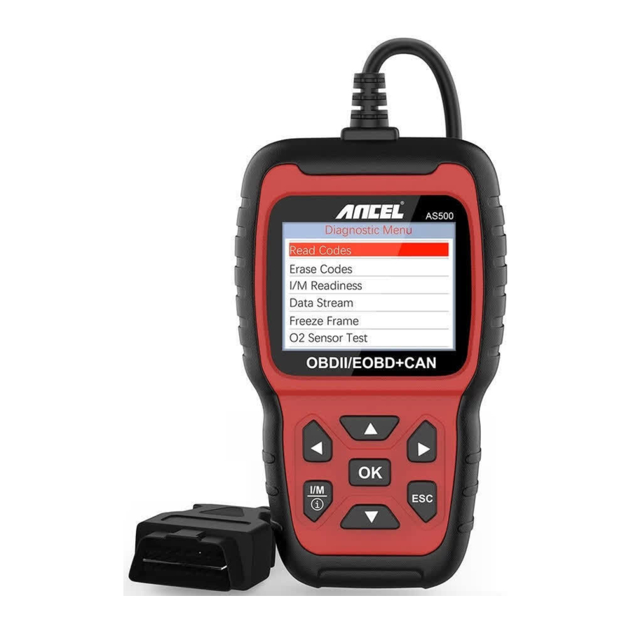
Tool Description - ANCEL AS500
- LCD DISPLAY
Indicates test results. Backlit, 320 x 240 pixels display - [OK] BUTTON
Confirms a selection (or action) from a menu. - [ESC]BUTTON
Cancels a selection (or action) from a menu or returns to the menu. - [LEFT ]SCROLL BUTTON
in the menu mode through the menu and sub menu move to the left, when rolling in a data interface, use the left button can be moved to the last screen - [RIGHT] SCROLL BUTTON
In the menu mode through the menu and sub menu item move to the right, when rolling in the data interface, use the right button can be moved to the next screen
- [UP] SCROLL BUTTON
In the menu mode through the menu and sub menu item moving up. When retrieving data for more than a screen by moving up the screen to the previous screen for more data - [DOWN] SCROLL BUTTON
In the menu mode through the menu and sub menu item moves down. When retrieving data more than one screen, by moving down the screen to the next screen for more data - [ I/M /
![]() ] SCROLL BUTTON
] SCROLL BUTTON
This mufti-function button can complete I/M readiness test and fault code definition query.
Note: Only when using the code reading function and the i icon appears on the screen, you can press this key to realize the fault code definition query. The button just can complete the I/M function in other situations
 ] SCROLL BUTTON
 Remarks:

MIL Yellow- Dashboard MIL ON
MIL Gray-Dashboard MIL OFF
 -not support
 -complete
 -not complete
Specifications
- Display: 2.8" TFT 262K true color
- Operating Temperature: 0 to 60ºC (32 to 140 Fº)
- Storage Temperature: -20 to 70ºC (-4 to 158 Fº)
- External Power: 8.0 to 18.0 V power provided via vehicle battery
- Dimensions: 167.9x97.3x32.1 mm
- Weight: 0.35kg
Accessories Included
- User's Manual - Instructions on tool operations
- USB cable - Used to upgrade the scan tool
Lookup
The DTC Lookup function is used to search for definitions of Code stored in the built-in Code library.
- From the Main Menu, use the UP/DOWN scroll button to select the Code Lookup and press the OK button


- For manufacturer specific codes, you'll need to select a vehicle make on an additional screen to look for DTC definitions. If definition could not be found (SAE or Manufacturer Specific), the scan tool displays "DTC definition not found! Please refer to vehicle service" manual!"
- To ESC to the Main Menu, press the ESC button.
Review
This function is used to review the recorded DTC. Select Review in the Main Menu and press OK and the screen will display the interface as shown below:

Setup
The scan tool allows you to make the following adjustments and settings:

- Language: Selects the desired language.
- Unit of Measure: Set measure to English or Metric
- Beep: Turns ON/OFF beep
- Record: ON/OFF the Record
- Background: Set background to Night mode or Day mode.
- Feedback
Review&Print DTC Data
- Connect to a computer via USB
- Download upgrade files from ANCEL website.
- Install upgrade driver according to the "upgrade instruction" file
- Open the "update" application.


- Click "Review & print" option. Then could save or print the DTC Data as needed.


Tool Infor
Choose [Tool Infor] and it displays as follow:

I/M
Choose [I/M] and it displays as follow:

After that, press OK button again, shown abbreviation definition as follow:


OBD II Diagnostics

Don't connect or disconnect any test equipment with ignition on or engine running
- Turn the ignition off.
- Locate the vehicle's 16-pin Data Link Connector (DLC).
- Plug the scan tool cable connector into the vehicle's DLC
- Turn the ignition on. Engine can be off or running.
- Press OK to enter Main Menu. UP /DOWN button to select Diagnostics from the menu


- Press OK to confirm. If "LINKING ERROR!" message shows on the display.
- Verify that the ignition is ON;
- Check if the scan tool's OBD II connector is securely connected to the vehicle's DLC;
- Turn the ignition 'off and wait for about 10 seconds. Turn the ignition back to 'on' and repeat the procedure from step 5.
Read Codes
- Select Read Codes and press OK in Diagnostic Menu. If there are some codes, the screen will display the codes as shown below:


- Only when using the code reading function and
![]() the icon appears on the screen, you can press this key I/M/
the icon appears on the screen, you can press this key I/M/![]() to realize the fault code definition query. The screen will display the interface as shown below:
to realize the fault code definition query. The screen will display the interface as shown below:


Erase Codes
- Select Erase Codes, the screen will display the interface as shown below. Press OK to erase DTC's, and the screen will display the interface as shown below:


- According to the above figure to press OK and the screen will display the interface as shown on the next page:


Notes: Before performing this function, make sure to retrieve and record the trouble codes. After clearing, you should retrieve trouble codes once more or turn ignition on and retrieve codes again. If there are still some trouble codes in the system, please troubleshoot the codes using a factory diagnosis guide, then clear the codes and recheck.
I/M Readiness
Select I/M Readiness and press OK, the screen will display the interface as shown below:

I/M readiness is to test Misfire / Fuel system / Comprehensive component, You can use UP or DOWN button to select and press OK, shown as follow:

N/A means not available on this vehicle, INC means incomplete or not ready, OK means Completed or Monitor Ok
Data Stream
Press UP or DOWN button to select Data Stream in Main Menu interface and then press OK button to confirm, the screen will display the interface as shown below:

Select [ View All Items ] and press OK button, the screen will display the interface as shown below:

Choose [ select items ] and press OK button. After that, press OK button again, shown as follow:

After selected items and press ESC, the screen will display as follow:

Press OK to select [ View Graphic Items ] in Data stream menu, after selected items, the screen will display the interface as shown below:

Press ESC to return to display.

Max lines is 3
Press ESC to return to previous menu. You can view all data stream items or select a certain item of live data with a graph
Freeze Frame
When an emission-related fault occurs, a snapshot of current vehicle parameter are recorded by the ECU Note: if DTCs were erased, Freeze Data may not be stored in vehicle. Select Freeze Frame in main menu interface, the screen will display the interface as shown below:

You can use UP/ DOWN button to view the to return to Diagnostic Menu.
O2 Sensor Test
OBD II regulations set by the SAE require that relevant vehicles monitor and test the oxygen (02) sensors to identify problems related to fuel efficiency and vehicle emissions. These tests are not on-demand tests and they are done automatically when engine operating conditions are within specified limits. These test results are saved in the on-board computer's memory. The O2 Sensor Test function allows retrieval and viewing of O2 sensor monitor test results for the most recently performed tests from the vehicle's on-board computer. The O2 Sensor Test function is not supported by vehicles which communicate using a controller area network (CAN). For O2 Sensor Test results of CAN-equipped vehicles, see chapter "On-Board Mon. Test". Select O2 Sensor Test in Diagnostic menu and press OK and the Screen will display as shown below. Press OK button, the screen will display as shown below (Data will be different every time):

On-Board Monitoring
This function can be utilized to read the results of on-board diagnostic monitoring Tests for specific components/systems. Select On-board Monitoring in Diagnostic Menu and press OK and the screen will display as shown below (Data will be different every time):

You can use UP or DOWN button to select an item and press OK, the screen will display as shown below (Data will be different every time):

Press ESC to return to Diagnostic Menu
Test or Component
The EVAP test function lets you initiate a leak test for the vehicle's EVAP system. The device does not perform the leak test, but signals to vehicle's on-board Computer to initiate the test. Before using the system test function, refer To The vehicle's service repair manual to determine the procedures necessary to stop the test. Select EVAP System Test and press OK, the screen will display the relative information about EVAP system. Some vehicle manufacturers do not allow External devices to control vehicle system. If the car supports this function, it will display as below:

Vehicle Information
Select [Vehicle Information] and press OK, the screen will display the information, such as VIN (Vehicle identification Number), CID (Calibration ID) and CVN (Calibration verification number), as shown below (different cars will shown different data)

Press ESC to return to Diagnostic Menu
Update
The device is connected with computer through USB cable
- When upgrade the device software, it only supports window 7/8/10 system
- It can be updated directly on Window8 and window 0 system
- When the computer is window7 system, the device's software driver is installed on the computer.
Feedback
- When the [OBDII] function shows connected error with vehicle, please using the feedback function. Choose [Feedback] and it displays as follow: Choose [Start recording] to open record function and it displays as follow: Next: Press ESC Button and return to the main menu. Choose [OBDII] menu to detecting again and it will record the data.
- Transfer data to your computer and generate feedback file. Download upgrade file on the computer from ANCEL website. The device is connected with computer through USB cable. Choose "Update" file and it displays as follow: Click "Feedback" and it displays as follow: Please send the feedback. bin file to support@anceltech.com.
Service Procedures
If you have any questions, please contact your local store, distributor or visit our website at www.anceltech.com
If it becomes necessary to return the scan tool for repair, contact your local distributor for more information.
Safety Precautions and Warnings
To prevent personal injury or damage to vehicles and/or the scan tool, read this instruction manual first and observe the following safety precautions whenever working on a vehicle:
- Turn the ignition off first, then connect 16-pin to plug, then turn the ignition on.
- Always perform automotive testing in a safe environment.
- Do not attempt to operate or observe the tool while driving a vehicle.
- Operating or observing the tool will cause driver distraction and could cause a fatal accident.
- Wear safety eye protection that meets ANSI standards.
- Keep clothing, hair, hands, tools, test equipment, etc. away from all moving or hot engine parts.
- Operate the vehicle in a well ventilated place: Exhaust gases are Poisonous.
- Put blocks in front of the drive wheels and never leave the vehicle unattended while running tests.
- Use extreme caution when working around the ignition coil, distributor cap, ignition wires and spark plugs. These components create hazardous voltages when the engine is running.
- Put the transmission in PARK (for automatic transmission) or NEUTRAL (for manual transmission) and make sure the parking brake is engaged.
- Keep a fire extinguisher suitable for gasoline/chemical/electrical fires nearby.
- Don't connect or disconnect any test equipment while the ignition is on or the engine is running.
- Keep the scan tool dry, clean, free from oil/water or grease.
- Use a mild detergent on a clean cloth to clean the outside of the scan tool, when needed.
Documents / Resources
References
Download manual
Here you can download full pdf version of manual, it may contain additional safety instructions, warranty information, FCC rules, etc.
Advertisement


Need help?
Do you have a question about the AS500 and is the answer not in the manual?
Questions and answers