Advertisement
Using This Manual
We provide tool usage instructions in this manual. Below is the conventions we used in the manual.
Bold Text
Bold text is used to highlight selectable items such as buttons and menu options. Example:
Press the ENTER button to select.
Symbols and Icons
Solid Spot
Operation tips and lists that apply to specific tool are introduced by a solid spot ●.
Example:
When Settings is selected, a menu that lists all available options displays. Menu options include:
- Language
- Unit
- Shortcuts
- Display Test
- Keypad Test
- About
Arrow Icon
 An arrow icon indicates aprocedure.
Example:
![]() To change menu language:
To change menu language:
- Scroll with the arrow keys to highlightLanguage on the menu.
- Press theENTER button to select.
Note and Important Message
Note
A NOTE provides helpful information such as additional explanations, tips, and comments. Example:
NOTE
Test results do not necessarily indicate a faulty component orsystem.

indicates a situation which, if not avoided, may result in damage to the device or vehicle.
Example:
Do not soak keypad as water might find its way into the scanner.
Introductions
AD610Plus Professional ABS & Airbag Reset Tool works on most vehicles on the road today. It does not only have extensive coverage of vehicles but also provides accurate and professional diagnosis of ABS and airbag faults.
Scanner Descriptions
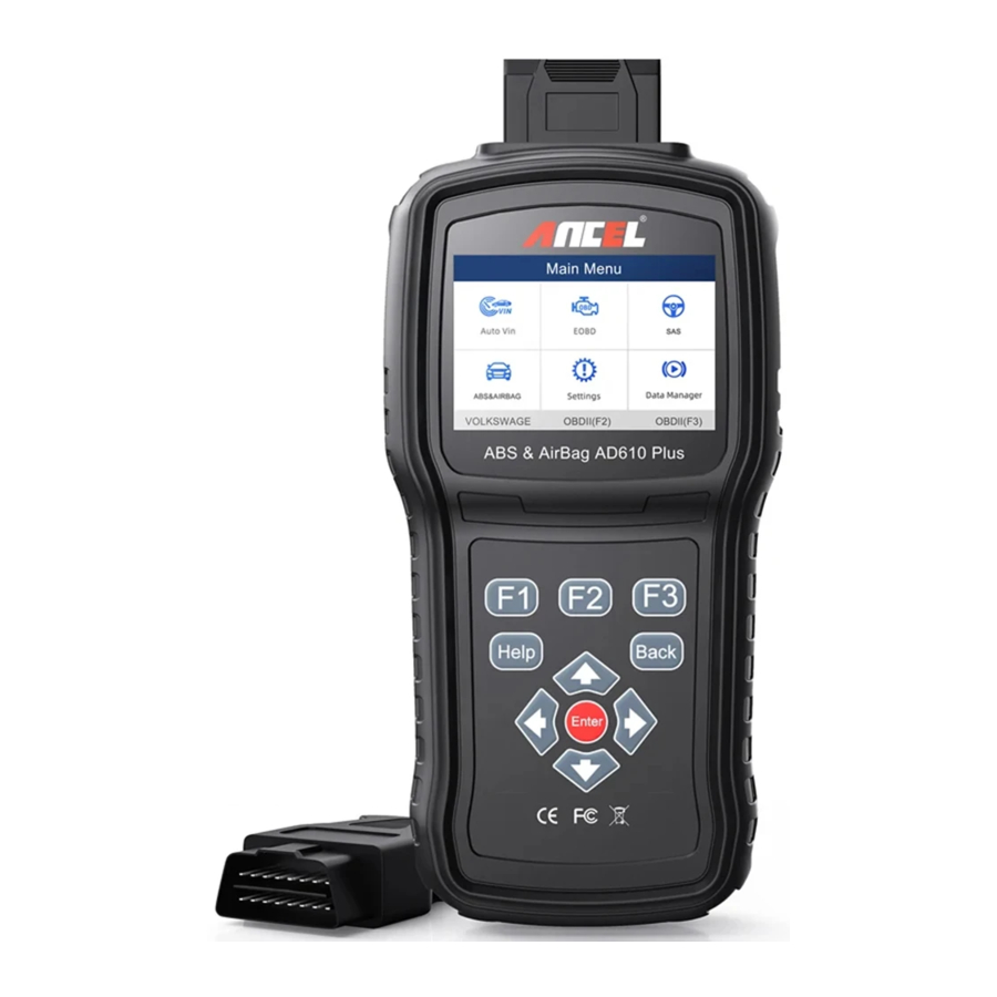
This section illustrates external features, ports and connectors of the scanner.
Figure 2-1 Front View

- Diagnostic Port - provides connection between vehicle and the scanner.
- LCD Display - shows menus, test results and operation tips.
- Function Keys / Shortcut keys - three keys that correspond with "buttons" on some screens for executing special commands or provide quick access to most frequently used applications or functions.
- Direction Keys - select an option or scroll through a screen of data or text.
- ENTER Key - executes a selected option and generally goes to the next screen.
- BACK Key - exits a screen and generally returns to previous screen.
- HELP Key - displays helpful information.
- USB Port - provides USB power connection between the scanner and PC/laptop.
- TF Card Port - holds the TF memory card for data backup and software update.
Do not use solvents such as alcohol to clean keypad or display. Use a mild nonabrasive detergent and a soft cotton cloth.
Accessory Descriptions
This section lists the accessories that go with the scanner. If you find any of the following items missing from your package, contact your local dealer for assistance.
- User's Guide - provides operation instructions for the usage of the scanner.
- Diagnostic Cable - provides connection between the scanner and a vehicle.
- USB Cable/Card Reader - provides connection between the scanner and a computer to update and print data.
- Nylon Carry Pouch - stores the scanner and its accessories.
Technical Specifications
Display: Back lit, 240*320 TFT color display
Working Temperature: 0 to 60 ℃ (32 to 140℉)
Storage Temperature: -20 to 70℃(-4 to 158℉)
Power Supply: 8-18V vehicle power and 3.3V USB power
Dimensions: (L*W*H): 200*100*38mm
Weight: 0.6 Kg
Getting Started
This section describes how to provide power to the scanner, provides brief introductions of applications loaded on the scanner and display screen layout and illustrates how to input text and numbers with the scan tool.
Providing Power to Scanner
Before using the scanner, make sure to provide power to the scanner.
The unit operates on any of the following sources:
- 12-volt vehicle power
- USB connection to computer
Connecting to Vehicle Power
The scanner normally powers on whenever it is connected to the data link connector (DLC).
![]() To connect to vehicle power:
To connect to vehicle power:
- Locate the data link connector (DLC). The DLC is generally located under the dash on the driver side of the vehicle.
- Attached the Diagnostic cable to the scanner and tighten the captive screws to ensure good connection.
- Connect a correct adapter to the data cable according to the vehicle being serviced and plug it into the vehicle DLC.
- Switch the ignition key to the ON position.
- The scanner automatically boots up.
Never try to provide power for the scan tool from USB connection when the scan tool is communicating with a vehicle.
Connecting to Computer with USB Cable
The scan tool also receives power through the USB port when it is connected to a computer for software updates and printing of data.
![]() To connect to computer:
To connect to computer:
- Connect the scanner to a computer with the USB cable provided.
Application Overview
When the scan tool boots up, the Home screen opens. This screen shows all applications loaded on the unit. The available vehicle applications may vary depending on software configuration.
Figure 3-1 Sample Home Screen

- Auto VIN - leads to screens for identifying a car by VIN reading.
- OBDII/EOBD - leads to OBDII screens for all 9 generic OBD system tests.
- SAS - leads to screens for steering angle calibration
- ABS & Airbag - leads to screens for diagnostic trouble code information, live data, ECU information and special functions of ABS and airbag systems on 49 vehicle makes sold worldwide.
- Settings - leads to screens for adjusting default settings to meet your own preference and view information about the scanner.
- Data Manager - leads to screens for access to data records.
- Update - leads to screen for updating the scanner.
Input Dialog Box
This section illustrates how to use the scan tool to input letters and numbers, such as VIN number, channel number, test values and DTC number. Typically, you may be required to input letters or numbers when you are doing any of the following operations.
- VIN entry
- input channel number
- set adaptation value
- enter block number
- enter login code
- key matching
- look up DTCs
The scan tool provides 4 different types of keyboard to meet your specific needs. Depending on the needs of text entry, it automatically shows the most suitable keypad.
- classic QWERTY keyboard for input of texts that contain both letters andnumbers
- numeric keyboard for input of numbers
- alphabet keyboard for input of letters
- hexadecimal keyboard for special functions, such as key matching, UDS coding
![]() To input text with the scan tool:
To input text with the scan tool:
- When you are requested to input text, press the function key Keyboard.

- Scroll with the arrow keys to highlight your desired letter or number and press the ENTER key to confirm.

- To delete a letter or number, use the function key Cursor Forward to move the cursor to it and then press the Backspace button.
- When finished the entry, press Completed key to continue.


Vehicle Identification
This section illustrates how to use the scanner to identify the specifications of the vehicle under test.
The vehicle identification information presented is provided by the ECM of the vehicle being tested. Therefore, certain attributes of the test vehicle must be entered into the scan tool to ensure the data displays correctly. The vehicle identification sequence is menu driven, you simply follow the screen prompts and make a series of choices. Each selection you make advances you to the next screen. Exact procedures may vary somewhat by vehicle. It typically identifies a vehicle by any of the following means:
- Automatic VIN reading
- Manual VIN entry
- Manual vehicle selection
NOTE
Not all identification options listed above are applicable to all vehicles. Available options may vary by vehicle manufacturer.
Auto VIN
Auto VIN is a shortcut for VIN reading menu which typically includes following options:
- Automatic VIN acquisition
- Manual input VIN
Automatic VIN Acquisition
Automatic VIN Acquisition allows to identify a vehicle by automatically reading the vehicle identification number (VIN).
![]() To identify a vehicle automatic VIN reading:
To identify a vehicle automatic VIN reading:
- Scroll with the arrow keys to highlight Auto VIN from the main menu and press the ENTER key.

- Select Automatic VIN Acquisition from the menu, and press the ENTER key.

- The scan tool starts to communicate with the vehicle and read the Vehicle Specification or VIN Code automatically.

- Answer YES if the Vehicle Specification or VIN code is correct and a menu of controller selection displays. Answer NO if it is incorrect, and you are required to enter the correct VIN number manually.

- If it takes too long to get the VIN code, pressCancel to stop and input the VIN manually. Or if failed to identify the VIN, please input the VIN manually or click Cancel to quit.


Manual VIN Entry
Manual VIN Entry identifies a vehicle by manually inputting a 17-digit VIN code.
![]() To identify a vehicle by manual VIN entry:
To identify a vehicle by manual VIN entry:
- Scroll with the arrow keys to highlight Auto VIN from the main menu and press the ENTER key.

- Select Manually input VIN from the menu, and press the ENTER key.

- Press the function key Keyboard and a virtual keyboard opens for VIN entry.

- Input a valid VIN code and use the function key Completed to confirm. The scan tool starts to identify the vehicle.


Manual Vehicle Selection
Select vehicle brand you are to test, and two ways of getting to the diagnostic operations are available.
- SmartVIN
- Manual Selection
SmartVIN
SmartVIN allows to identify a vehicle by automatically reading the vehicle identification number (VIN).
To identify a vehicle by SmartVIN:
- Scroll with the arrow keys to highlight ABS & Airbag from main menu and press the ENTER key to start. If you have the application assigned to one of the function keys at the bottom of the screen, you can alternatively press the function key to start the application.

- A screen with vehicle manufacturer areas displays. Select the area where the car brand is originated. A list of vehicle makesdisplay.

- Select the vehicle manufacturer. A list of vehicle identification optionsdisplays.

- Select SmartVIN from the menu, and press the ENTER key.

- The scan tool starts to communicate with the vehicle and read the Vehicle Specification or VIN Code automatically.

- Answer YES if the Vehicle Specification or VIN code is correct and a menu of controller selection displays. Answer NO if incorrect, and you are required to enter the correct VIN number manually.


Manual Selection
Manual Selection identifies a vehicle by making several selections according to certain VIN characters, such as model year, and engine type.
![]() To identify a vehicle by manual vehicle selection:
To identify a vehicle by manual vehicle selection:
- Refer to step 1-3 of 4.2.1 SmartVIN.
- On each screen that appears, select the correct option and then press theENTER key. Do this until the complete vehicle information is entered and the menu of controller selectiondisplays.


Diagnostic Operations
This section illustrates how to use the scanner to read and clear diagnostic trouble codes, and view "live" data readings and ECU information on controllers installed on a variety of vehicles and also save "recordings" of the data readings.
Control Module Selection
When you completed the identification of vehicle, you have to identify the control modules installed in the vehicle. There are two ways to identify the controllers installed in a car:
- Quick Scan
- Control Modules
Quick Scan
Quick Scan performs an automatic system test to determine which control modules are installed on the vehicle and provides diagnostic trouble codes (DTCs) overview. Depending on the number of control modules, it may take 10 minutes or longer to complete the test.
To perform an automatic system scan:
- Scroll with the arrow keys to highlight Quick Scan from the menu and press ENTER tostart.

- To pause the scan, press the function key corresponding with Pause on the screen.

- At the end of successful automatic controller scan, a menu with a list of installed controllers together with their DTC overview displays.
![]()
- If there is diagnostic trouble code(s) detected in a control unit, press the function key corresponding withReport on the screen to view details of code information. Or press the function key Erase to clear them.

- Press function key F1 to save the trouble code information.
- Select the system you would like to test, and press the ENTER key. When the scanner has established connection with the vehicle, the Function Menu displays.


Control Modules
Control Modules screen displays all controllers available on the vehicles. The controllers listed on the menu do not mean that they are installed on the vehicle.
To select a system for testing:
- Scroll with the arrow keys to highlight Control Modules from the menu and press the ENTER key. A controller menu displays.

- Select the system you would like to test. When the scanner has established connection with the vehicle, the Function Menu displays.


Diagnostic Operations
After a system is selected and the scanner establishes communication with the vehicle, the Function Menu displays. The menu options may include:
- ECU information
- Read Codes
- Clear Codes
- Live Data
- Special Functions
NOTE
Not all function options listed above are applicable to all vehicles. Available options may vary by the year, model, and make of the test vehicle.
ECU Information
ECU Information screen displays the identification data of the control module under test, such as the control module identification string, the control module coding, and Work Shop Code.
To read ECU information:
- Select ECU Information from the menu and press the ENTER key.

- A screen with detailed information of the selected control moduledisplays.

- Press function key Save to store ECU information. Or use the BACK key to exit.


Read Codes
Read Codes menu lets you read trouble codes found in the control unit.
Typical code status include:
- Present/Permanent/Current Codes
- Pending Codes
- History Codes
Present/Permanent/Current codes stored in a control module are used to help identify the cause of a trouble or troubles with a vehicle. These codes have occurred a specific number of times and indicate a problem that requires repair.
Pending codes are also referred to as maturing codes that indicate intermittent faults. If the fault does not occur within a certain number of drive cycles (depending on vehicle), the code clears from memory. If a fault occurs a specific number of times, the code matures into a DTC and the MIL illuminates or blinks.
History codes are also referred to as past codes that indicate intermittent DTCs that are not currently active.
![]() To read codes from a vehicle:
To read codes from a vehicle:
- Scroll with the arrow keys to highlightRead Codes from Function Menu and press the ENTER key. A code list including code number and its description displays.

- Use the up and down arrow keys to scroll through data to select lines, and left and right arrow keys to scroll back and forth through different screens of data.

- Press function keySave to store DTC information. Press function key Freeze Frame to view freeze data.
Freeze Frame Data: a snapshot of critical vehicle operating conditions automatically recorded by the on-board computer at the time of the DTC set. It is a good function to help determine what caused the fault.

- Use left and right arrow keys to scroll back and forth through different screens of data.
- Press function keySave to store freeze frame information. Or use the BACK key to exit.


Clear Codes
Clear Codes menu lets you to clear all current and stored DTCs from a selected control module. Also it erases all temporary ECU information, including freeze frame. So make sure that the selected system is completely checked and serviced by technicians and no vital information will be lost before clearing codes.
NOTE
- To clear codes, make sure that the ignition key is switched to ON with the engine off.
- Clear Codes does not fix the problem that caused the fault! DTCs should only be erased after correcting the condition(s) that causedthem.
To clear codes:
- Scroll with the arrow keys to highlight Clear Codes from Function Menu and press the ENTER key.

- Follow the on-screen instructions and answer questions about the vehicle being tested to complete the procedure.

- Check the codes again. If any codes remain, repeat the Clear Codes steps.


Live Data
Live Data menu lets you view and record real time PID data from a selected vehicle electronic control module.
Menu options typically include:
- Complete List
- Custom List
Complete Data List
Complete List menu lets you view all live PID data from a selected system.
To view live PID data:
- Scroll with the arrow keys to highlight Live Data from the menu and press the ENTER key.

- Select the Complete List from the menu and press the ENTER key to display the datascreen.

- Scroll with the up and down arrow keys to highlight a line, and left and right arrow keys to scroll back and forth through different screens of data. Press function key Pause to suspend collecting data from the vehicle and use the Start key to resume collecting data. To record data to memory of the scanner, use the function key SAVE, and press Stop Saving to stop recording at anytime.

- Use up and down arrow key to select line. If Graph is highlighted, it indicates graphing is available for the selected line. Press the function key Graph to display the PID graph.

- Press the function key Multi-graphs to display two PID graphs in one screen. Press Single graph to view one plot.

- Press the function key Merge Graph to display two PID plots in one coordinate to check how they affect each other.

- Press the Back key to return to the previous menu.


Custom List
Custom List menu lets you to minimize the number of PIDs on the data list and focus on any suspicious or symptom-specific data parameters.
To create a custom data list:
- Select Custom List from the menu and press the ENTER key.

- The custom data selection screen displays. Scroll with the up and down arrow keys to highlight a line, press the ENTER key and then repeat the action to make more selections. To deselect an item, select it again and then press the ENTER key. Alternatively, use the function keys Select All and Deselect to select or deselect all items at once.

- When finished selection, use the function key OK to display selected items.


Special Functions
Special tests are bi-directional diagnostic tests on anti-lock brake systems and air bags. The tests let you to use the scanner temporarily activate or control a vehicle system or component, and when you exit the test, the system/component returns to normal operation.
Some tests display a command to the operator. For example, if "Press Brake Pedal" displays, the operator has to press and hold the brake pedal and then continue. The number, and type of tests will vary for each vehicle, year and components.
Typical special test options include:
- ABS Manual Control Tests – allows to manually control the actuators in order to test ABS motors, solenoids, solenoid enable relays, EMBs, and more.
- ABS Motor Test – allows to manually control the ABS pump motor.
- ABS Version Test – displays the name of the brake system and the ABS controller version number, software ID, and sequence value.
- Actuator Tests – allows to manually control the actuators in order to test AYC valves, inlet valves, outlet valves, pump motors, and TRACS valves.
- Auto Bleed Test, Automated Bleed, or Service Bleed – removes air from the internal brake fluid chambers after servicing the brakes.
Before bleeding the brake system, make sure no diagnostic codes are present. Do not let the master cylinder run dry during the brake bleeding procedure.

After bleeding the brake system, check the brake pedal for excessive travel or a "spongy" feel. Bleed again if either condition is present.
- Automated Test - automatically commands each solenoid valve and the pump motor on and off to test for proper operation.
- Brake Bleed Preparation Test - prepares the brake lines for bleeding by clearing air from the modulator. The test rehomes all the ABS and TCS motors, cycles the TCS motors, and then returns all motors to the "home" position at the bottom of thebore.
- Function Test - automatically commands the ABS relay, valve solenoids, and pump motor on and off to test for proper operation.
- Gear Tension Relief Test - relieves tension from the ABS motor gears so you can separate the ABS motor pack from the ABS hydraulicmodulator.
- Hydraulic Control Tests - allows to manually engage and disengage the ABS solenoids for troubleshooting the hydraulic functions.
- Idle Up Manual Control Test - allows to manually control the idle upactuators.
- Lamp Tests - allows to manually control the ABS or TCS warning or indicator lamps.
- Motor Rehome Test - prepares the brake lines for bleeding by clearing air from the modulator. The test returns all ABS motors to their "home"positions.
- Pump Motor Tests - allows to manually control the pump motor.
- Relay Test - allows to manually engage and disengage either the ABS or TCS relays in order to test relay operation.
- Requested Torque Test - allows to manually control the engine torque to test for proper operation of the traction control system (TCS).
- Setup SDM Serial Number (Air Bag Sensing and Diagnostic Module) - allows to program a new air bag serial number into the dash integration module (DIM). You use this test after installing a new air bag; otherwise a diagnostic trouble code will be set when you turn on the ignition.
- Solenoid Tests - allows to manually control the inlet and output valvesolenoids.
- System Identification - displays information about the brake system, the vehicle, and the ABS controller.
- TCS Test - allows to control the pump motor in order to apply fluid pressure to the front wheel circuits.
- Traction Control System (TCS) Manual Control Tests - allows to perform motor tests and an adjuster assembly control test.
- Voltage Load Test - "loads" the ABS battery supply circuit to test for adequate battery capacity.
To perform special tests on a vehicle:
- Scroll with the arrow keys to highlight the special function test you want to perform fromthe menu and press the ENTER key.

- A group selection screen, test selection screen, several step-by-step instruction screens, or bidirectional control screen may appear. Read the screens and follow all instructions. If necessary, use the function keys to perform commands or answer any questions. If more than 3 function keys displays, use up and down arrow keys to select a command and press the ENTER key to confirm.

- When completed, press the BACK key to return to previous screens.


NOTE
Not all function options listed above are applicable to all vehicles. Available options may vary by the year, model, and make of the test vehicle.
Steering Angle Sensor (SAS) Calibration
SAS Calibration menu lets you perform calibration of the steering angle sensor, which permanently stores the current steering wheel position as straight-ahead in the sensor EEPROM. On successful calibration of the sensor, its fault memory is automatically cleared.
To start a test:
- Scroll with the arrow keys to highlight SAS from the main menu and press the ENTER key.
 Calibration - Step 1")
- On each screen that appears, select the correct option and then press the ENTER key. Read the screens and follow all instructions to complete the test.
 Calibration - Step 2")
 Calibration - Step 1")
 Calibration - Step 2")
OBDII/EOBD Operations
OBDII/EOBD menu lets you access all OBD service modes. According to ISO 9141-2, ISO 14230-4, and SAE J1850 standards, the OBD application is divided into several sub programs, called 'Service $xx'. Below is a list of OBD diagnostic services:
- Service $01 - request current powertrain diagnostic data
- Service $02 - request powertrain freeze frame data
- Service $03 - request emission-related diagnostic trouble codes
- Service $04 - clear/reset emission-related diagnostic information
- Service $05 - request oxygen sensor monitoring test results
- Service $06 - request on-board monitoring test results for specific monitoredsystems
- Service $07 - request emission-related diagnostic trouble codes detected during currentor last completed driving cycle
- Service $08 - request control of on-board system, test orcomponent
- Service $09 - request Vehicle Information
When OBDII/EOBD application is selected from Home screen, the scanner starts to detect the communication protocol automatically. Once the connection has established, a menu that lists all of the tests available on the identified vehicle displays. Menu options typically include:
- System Status
- Read Codes
- Freeze Frame Data
- Clear Codes
- Live Data
- I/M Readiness
- O2 Sensor Test
- On-board Monitor Test
- Component Test
- Vehicle Information
- Modules Present
- Code Look-up
NOTE
Not all function options listed above are applicable to all vehicles. Available options may vary by the year, model, and make of the test vehicle. A "Not supported the mode!" message displays if the option is not applicable to the vehicle undertest.
System Setup
This section illustrates how to program the scanner to meet your specific needs.
When Settings is selected, a menu with available service options displays. Menu options typically include:
- Language
- Unit
- Shortcuts
- Display Test
- Keypad Test
- About
Select Language
Selecting Language opens a screen that allows you to choose system language. The scan tool is set to display English menus by default.
To configure system language:
- Scroll with the arrow keys to highlight Language from Settings menu and press ENTER key.

- Press left and right arrow key select a language and press the ENTER key to confirm. Press the Back key to exit and return


Change Units
Selecting Unit opens a dialog box that allows you to choose units of measure.
![]() To change the unit setup:
To change the unit setup:
Scroll with the arrow keys to highlight Units from Settings menu and press the ENTER key.

- Press the up and down arrow key select an item and press the ENTER key to save andreturn.


Configure Shortcut Keys
Selecting Shortcuts option lets you to change the functionality of the shortcut buttons.
To assign a function to a shortcut button:
- Scroll with the arrow keys to highlight Shortcuts from Settings menu and press the ENTER key. A screen with available shortcut keys displays.

- Press the up and down arrow key select a shortcut key and press the ENTER key. A screen with a list of loaded applications displays.

- Scroll with the arrow keys to highlight an application and press the ENTER key to assign the application to the shortcut key
![]()


Display Test
Selecting Display Test option opens a screen that allows you to check the functionality of the display.
To test the display:
- Scroll with the arrow keys to highlight Display Test from Settings menu and press the ENTER key to start test. Check if there are any missing spots in the LCD screen.

- xFigure 8-8 Sample LCD Test ScreenTo quit the test, press the Back key.

Keypad Test
Selecting Keypad Test option opens a screen that allows you to check the functionality of the keypad.
![]() To test the keypad:
To test the keypad:
- Scroll with the arrow keys to highlight Keypad Test from Settings menu and press ENTER key.

- Press any key to start test. The virtue key corresponding with the key you pressed will be highlighted on the screen if it works correctly.

- To quit the test, press Back key twice.


Tool Information
Selecting About option opens a screen that shows information about your scan tool, such as serial number, which may be required for product registration.
To view information of your scan tool:
- Scroll with the arrow keys to highlight About from Settings menu and press the ENTER key
![]()
- A screen with detailed information of the scanner displays.

- Press the Back key to exit.


Update
The scanner can be updated to keep you stay current with the latest development of diagnosis. This section illustrates how to register and update your scan tool.
![]() To update your scanner, please follow the three steps as below:
To update your scanner, please follow the three steps as below:
- Obtain an ANCEL ID.
- Register the product with the product serial number.
- Update the product by the update application AncelScanner.
For step 1 and 2, you can also go to our site with the link below.
- https://anceltech.com/support/download
Safety Information
For your own safety and the safety of others, and to prevent damage to the device and vehicles, read this manual thoroughly before operating your scanner. The safety messages presented below and throughout this user's manual are reminders to the operator to exercise extreme care when using this device. Always refer to and follow safety messages and test procedures provided by vehicle manufacturer. Read, understand and follow all safety messages and instructions in this manual.
Safety Message Conventions Used
We provide safety messages to help prevent personal injury and device damage. Below are signal words we used to indicate the hazard level in a condition.

Indicates an imminently hazardous situation which, if not avoided, will result in death or serious injury to the operator or to bystanders.
Indicates a potentially hazardous situation which, if not avoided, could result in death or serious injury to the operator or to bystanders.

Indicates a potentially hazardous situation which, if not avoided, may result in moderate or minor injury to the operator or to bystanders.
Important Safety Instructions
And always use your scanner as described in the user's manual, and follow all safety messages.
- Do not route the test cable in a manner that would interfere with driving controls.
- Do not exceed voltage limits between inputs specified in this user's manual.
- Always wear ANSI approved goggles to protect your eyes from propelled objects as well as hot or caustic liquids.
- Fuel, oil vapors, hot steam, hot toxic exhaust gases, acid, refrigerant and other debris produced by a malfunction engine can cause serious injury or death. Do not use the scanner in areas where explosive vapor may collect, such as in below-ground pits, confined areas, or areas that are less than 18 inches (45 cm) above the floor.
- Do not smoke, strike a match, or cause a spark near the vehicle while testing and keep all sparks, heated items and open flames away from the battery and fuel / fuel vapors as they are highly flammable.
- Keep a dry chemical fire extinguisher suitable for gasoline, chemical and electrical fires in work area.
- Always be aware of rotating parts that move at high speed when an engine is running and keep a safe distance from these parts as well as other potentially moving objects to avoid serious injury.
- Do not touch engine components that get very hot when an engine is running to avoid severe burns.
- Block drive wheels before testing with engine running. Put the transmission in park (for automatic transmission) or neutral (for manual transmission). And never leave a running engine unattended.
- Do not wear jewelry or loose fitting clothing when working on engine.
- Don't connect or disconnect the device while the ignition is on or the engine is running.
Documents / ResourcesDownload manual
Here you can download full pdf version of manual, it may contain additional safety instructions, warranty information, FCC rules, etc.
Advertisement


Need help?
Do you have a question about the AD610 Plus and is the answer not in the manual?
Questions and answers