Advertisement
INTRODUCTION
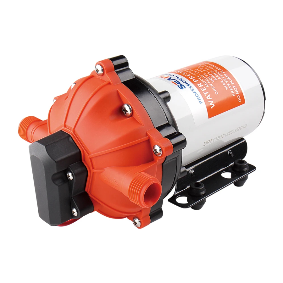
An economical workhorse, the 55 series are engineered for flexibility. The 5 chamber series are our Heavy-Duty water pump. It provides high volume water flow with reduced pump cycling, thanks to the large five-chamber diaphragm. With on-demand switch, 3.0 to 5.0 GPM, and 70 PSI, new demand switch, control of pressure precise, stable performance, low starting pressure, good heat dissipation, the 55 series will meet your special requirements with positive predictable performance. With built-in bypass function, 55 series is able to reduce rapid cycling and allow water to flow back from the outside to the inlet side of the pump. SEAFLO also offers a variety of easy connect fittings and filters.
FEATURES
- 5 chamber diaphragm pump
- New demand switch
- Industry standard mounting pattern
- Run dry capable for normal workloads
- Automatic: controlled by pressure switch
- Ignition protected
- Self priming
- Continuous duty
APPLICATIONS
- Yacht/RV/caravan pressurized water system
- Sprayer fixtures (vehicle-mounted sprayers, electric sprayers)
- Cleaning machines, humidifier, water purification, medical apparatus
- Food beverage filling & liquid transfer Solar water system
- Any other pressurization system
INSTALLATION
Materials
1 diaphragm pump with related accessories
4 stainless steel hose clamps and screws
4 screws to fasten the pump to the mounting surface
2 (at least) pieces of flexible, reinforced hose piping, with collapsing strength of twice the inlet collapsing pressure, hose must be minimum 1/2" ID
1 electrical cutoff switch
1 fuse
1 screwdriver
1 strong cutting implement for tubing
(if desired) Teflon tape or sealant
Setup
- The pump may be mounted in any position. If mounted vertically, the pump head should be in the down position to avoid leakage into the motor casing in the event of a malfunction.
- Secure the feet, but do not compress them. Over tightening the securing screws may reduce their ability to dissipate noise and vibration.
- Intake hose must be minimum 1/2" (13 mm) ID reinforced hose. Main distribution line from pump outlet should also be 1/2" (13 mm) ID with branch and individual supply lines to outlets no smaller than 3/8" (10 mm).
- Plumb the system using high pressure (2x pump rating), braided, flexible tubing to minimize vibration/ noise.
- Do not apply inlet pressure in excess of 30 psi. In general, try to avoid any inlet pressure completely.
- Avoid any kinks or fittings which could cause excessive restrictions.
- Strainer should be attached to the inlet side.
- The fittings must be secured to avoid leakage.
- Use clamps at both ends of hose to prevent air leaks into the water line.
- If a check valve is installed in the plumbing, it must have a cracking pressure of no more than 2 psi.
- lf applying a sealer or plumbing tape, be careful to not overtighten, as they may be sucked into pump.
- This pump should be wired on its own dedicated circuit. Connect the positive lead (red) to the positive terminal of your battery and the negative wire (black) to the negative terminal of your battery.
- In an easily accessible location, install a switch to control electricity to the pump. Turn the pump off when not used for extended periods or when the tank is empty.
- The electrical circuit should be protected with an over-current protection device (fuse) in the positive lead. This pump requires a 25 amp fuse.
- The pump circuit should not include any other electrical loads.
- As the water supply pump is non-essential, reference the wire chart under the electrical information. Be sure to have the correct wire sizing for the length of wire you are using.
- After installation, check the voltage at the pump motor. Voltage should be checked when pump is operating. Full voltage must be available at the pump motor at all times.
Notes
- Flexible potable water hose or PEX tubing is recommended instead of rigid piping at pump. If you choose to use rigid piping, provide a short length of hose between pipe and the pump to avoid noise and vibration.
- SEAFLO does not recommend the use of metal fittings. When possible, use the provided plastic fittings.
- Do not adjust the bypass personally without the help of technician.
- Lack of sanitizing and maintenance is one of the main reasons of under performance of the pump. Please do maintenance and winterize the pump at appropriate times, especially before and after a period of storage.
REPAIR KITS

ELECTRICAL INFORMATION
| Ft.(M) | 0-20(0-6) | 20-30(6-9) | 30-50(9-15) | 50-65(15-19) |
| AWG(MM2) | 14 AWG | 12 AWG | 10 AWG | 8 AWG |
TROUBLESHOOTING
PULSATING FLOW - UNIT CYCLES ON AND OFF
- Plumbing lines or fittings may be too small.
- Check fitting tightness for air leaks.
- Check lines for kinks.
- Clean faucets and filters.
FAILURE TO PRIME BUT MOTOR OPERATES - NO UNIT DISCHARGE
- Restricted intake or discharge line.
- Punctured pump diaphragm.
- Initial amp supply is not enough to sufficiently start the motor
- Air leak in intake line.
- Debris clogged in the valves.
- Crack in pump housing.
MOTOR FAILS TO TURN ON
- Loose or improper wiring.
- Pump circuit has no power.
- Blown fuse.
- Failed pressure switch.
- Defective motor.
PUMP FAILS TO TURN OFF AFTER ALL FIXTURES ARE CLOSED
- Punctured diaphragm.
- Discharge line leak.
- Defective pressure switch.
- Insufficient voltage.
- Clogged valves in pump head.
LOW FLOW AND PRESSURE
- Air leak at pump intake.
- Punctured diaphragm.
- Defective motor.
- Accumulation of debris inside pump or plumbing.
- Worn pump bearing (possibly accompanied by loud noise).
NOISY
- Check if the mounting feet are compressed too tightly.
- Is the mounting surface flexible? If so, it may be adding noise.
- Check for loose head/screws.
- If the pump is plumbed with rigid pipe, then it may transmit noise more easily.
USE THE FOLLOWING PROCESS TO ADJUST SHUT-OFF AND BY-PASS PRESSURES
- lnstall the pump as the picture 1.
![]()

ADJUSTING THE BYPASS VALVE AND PRESSURE SWITCH
 TIP: Bypass adjustment should be performed by a professional technician using a proper gauge and equipment. Without the proper equipment, you could mis-adjust the valve or switch causing the pump to work improperly (see Caution below).
About the Bypass Valve
The pump uses a spring-loaded bypass valve to maintain smooth performance as water demands rise and fall. When a faucet is turned on the pump is providing full water flow, so the bypass valve is closed. But when there is little to no water demand, the bypass valve opens to allow water to flow back from the outlet side to the inlet side, keeping a steady flow of water within the pump with almost no cycling.

See Picture 2.
- ADJUSTING THE PUMP'S SHUT-OFF PRESSURE:
- To raise the shut-off pressure, use a 2mm Allen wrench to tum the pressure switch screw clockwise to the desired pressure.
- To lower the shut-off pressure, use a 2mm Allen wrench to turn the pressure switch screw counter-clockwise to the desired pressure.
- ADJUSTING THE BYPASS:
Slide a screwdriver in the removal slot and pry out bypass valve access hole cover.
Locate the bypass valve adjustment screw on the pump housing at the bottom of the access hole.- To raise the pressure at which the bypass starts and raise the full bypass pressure, use a 2mm Allen wrench to turn the bypass screw clockwise to the desired pressure.
- To lower the pressure at which the bypass starts and lower the full bypass pressure, use a 2mm Allen wrench to turn the bypass screw counter-clockwise to the desired pressure.

The pressure setting for full bypass must be at least 8psi higher than the shut-off pressure of the pump. If the switch and bypass is adjusted too closely, the bypass and switch shut-off can overlap and the pump will not shut off.
ABOUT THE BYPASS
Please consult a professional technician in the case that the bypass needs adjustment. Improper adjustment of the bypass may damage the pump.
The bypass comes preset for optimal operation of the pump. If your application calls for a different setting for the bypass, you may change it yourself. Carefully tighten the screw to increase or loosen the screw to decrease the minimum operational pressure of the bypass.
ABOUT NEW SWITCH
We use new demand switch for the pump, it can control of pressure more precise and have good stable performance.
And low starting pressure, protect the pump start frequently. Good heat dissipation, the switch is directly in contact with the liquid, so that can serve as a cooling function to prevent the switch from burning out. Also the switch sealing performance is better.
Please do follow the instruction manual to install the product. Any action outside what is recommended in this manual may bring damage to the pump. Any inappropriate installation or operation that causes the pump damage is not covered by warranty.
Documents / ResourcesDownload manual
Here you can download full pdf version of manual, it may contain additional safety instructions, warranty information, FCC rules, etc.
Advertisement


Need help?
Do you have a question about the 55 Series and is the answer not in the manual?
Questions and answers