Table of Contents
Advertisement
Advertisement
Table of Contents

Related Manuals for Phanteks NV7


Summary of Contents for Phanteks NV7
- Page 1 USER MANUAL VERSION 1.0...
-
Page 3: Table Of Contents
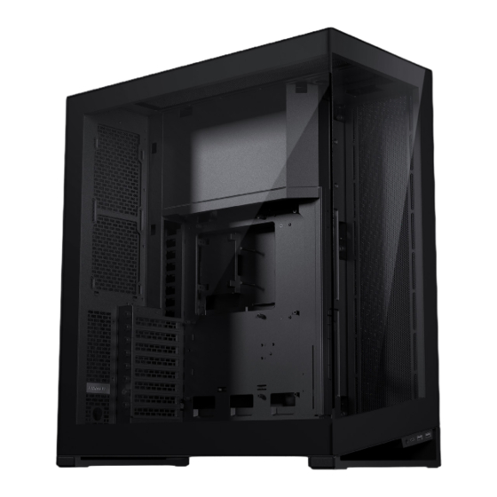
INTRODUCING THE PHANTEKS Introduction Move Front I/O To Secondary Position The Phanteks NV7 is a showcase full-tower chassis with a clean look from every side. It is the first D-RGB Lighting Effects D-RGB Cables installment of the new NV series, which is focused on showcasing your hardware in a premium build-quality chassis. -
Page 4: Exploded View
LIGHTING EFFECTS EXPLODED VIEW The Digital-RGB lighting can be easily MODES PARTS controlled with the 4 buttons on top of Chassis the chassis: Solid LIGHT WHITE MAGENTA PINK ORANGE GOLD YELLOW GREEN TEAL BLUE BLUE Front glass panel Right side mesh panel Rainbow Left glass panel Top panel... -
Page 5: Accessories
ACCESSORIES SPECIFICATIONS CASE SPECIFICATIONS INCLUDED ACCESSORIES GPU SUPPORT BRACKET AIRFLOW COVER Dimension (DxWxH) 532 x 253 x 586 mm / 20.9 x 10.0 x 23.1 in GPU Support Bracket Included in accessory box 2x Included in accessory box Form Factor Full Tower Airflow Cover Materials... -
Page 6: Remove External Panels
REMOVE EXTERNAL PANELS REMOVE EXTERNAL PANELS OPEN REAR PANEL REMOVE GLASS SIDE PANEL REMOVE GLASS FRONT PANEL REMOVE TOP PANEL REMOVE RIGHT SIDE PANEL REMOVE REAR DOOR LOOSEN REMOVE LOOSEN REMOVE THUMB SCREW SCREW THUMB SCREW SCREW Open the rear door by pulling it from the Loosen the 2 thumb screws in the rear, Unscrew the 2 screws from the left side Loosen the 2 thumb screws of the top... -
Page 7: Motherboard Installation
REMOVE COVERS MOTHERBOARD INSTALLATION REMOVE D-RGB COVER REMOVE MOTHERBOARD COVER ALIGN MOTHERBOARD Align the motherboard with the screwholes on the chassis’ motherboard tray. SECURE MOTHERBOARD Secure the motherboard with 9x motherboard screws. PRO TIP Use the included stand-off tool to REMOVE 1. -
Page 8: Power Supply Installation
POWER SUPPLY INSTALLATION RADIATOR & FAN POSITIONS SECURE PSU INSERT PSU RADIATOR POSITIONS FAN POSITIONS Side: up to 360 Top: up to 360 Side: 4x 120 mm Top: 3x 120 mm Insert the PSU from the right side of the chassis. Secure the PSU from the rear with 4x PSU screws. -
Page 9: Fan & Radiator Installation
RECOMMENDED AIRFLOW CONFIGURATIONS FAN & RADIATOR INSTALLATION AIR-COOLED CONFIGURATION WATER COOLED CONFIGURATION SIDE FAN/RADIATOR BRACKET REMOVE SCREW Side: Intake Top: Exhaust Side: Exhaust Top: Exhaust Remove the screw located on the top. Bottom: Intake Rear: Exhaust Bottom: Intake Rear: Exhaust PULL &... - Page 10 FAN & RADIATOR INSTALLATION FAN & RADIATOR INSTALLATION BOTTOM FAN/RADIATOR BRACKET REAR FAN/RADIATOR POSITION The rear has space for up to 240 radiator REMOVE BOTTOM BRACKET radiator routing cut-outs and 2x 120 fans. The fans can be installed Release the bracket by removing the in front of the rear panel while the routing cut-out rear thumb screw.
-
Page 11: Power Button & Led
FAN & RADIATOR INSTALLATION POWER BUTTON AND LED TOP FAN/RADIATOR POSITION CONNECT POWER BUTTON routing cut-out Connect the power switch module to INSTALL FANS/RADIATOR the motherboard. Up to 3x 120 fans/360 radiator can be directly installed into the top of the chassis. -
Page 12: Front I/O
FRONT I/O MOVE FRONT I/O TO SECONDARY LOCATION I/O INTERFACE STEPS TO MOVE I/O TO THE REAR • USB 3.1 GEN 2 TYPE-C (1x) REMOVE BOTTOM FAN BRACKET • USB 3.0 TYPE-A (2x) Remove the bottom fan bracket. • Headphone/microphone (1x) REMOVE SCREWS Unscrew 2x screws located inside the chassis. -
Page 13: D-Rgb Cables
INSTALL 2.5’’ DRIVES TO SATA PSU Install up to 2x 2.5’’ drives with 2x SSD screws per SSD. EXPAND WITH OTHER D-RGB PRODUCTS To Phanteks Digital-RGB products (JST connector) TO TOP IO PANEL 2.5’’ DRIVE 2.5’’ DRIVE CHANNEL A PORTS... -
Page 14: Internal Cable Management
INSTALLING STORAGE INTERNAL CABLE MANAGEMENT PSU CABLE MANAGEMENT BOTTOM DOOR STORAGE The PSU cables can be routed like the image OPEN BOTTOM DOOR OPTION B - 4X 2.5’’ OPTION C - 2X 3.5’’ below for clean cable management. Open the Loosen the thumb screw to open the door. -
Page 15: Installing Led Covers
INSTALLING LED COVERS INSTALLING LED COVERS INSTALL MOTHERBOARD COVER INSTALL D-RGB COVER The motherboard cover can be installed in two ways: 3. secure with Option 1: Default Option 2: Reversed thumbscrew The first option covers a bit more of the cables attached to For the second option, the cover is installed in reversed position. -
Page 16: Installing Gpu Support Bracket
INSTALLING GPU SUPPORT BRACKET (OPTIONAL) EXTERNAL CABLE MANAGEMENT CABLE LANES VELCRO TIE COMB OR GROMMET INSTALL BRACKET ADJUST HEIGHT ADJUST DEPTH External cables can be managed with the Use the velcro tie on the bottom to tie all There are two options for the cables to leave Install the GPU support bracket on the Adjust to the correct height for your GPU Adjust the depth of the bracket to hold... -
Page 17: Support
WARRANTY As a Phanteks customer, you are priority number one. We have a dedicated team of employees across the globe working hard Phanteks warrants its products to be free from defects in material and workmanship during the warranty period; when given every day to make sure we deliver the superior experience you deserve. - Page 18 FOLLOW US SOCIAL MEDIA Instagram Phanteks Facebook Phanteks YouTube Phanteks Twitter @phanteks...
Need help?
Do you have a question about the NV7 and is the answer not in the manual?
Questions and answers