Table of Contents
Advertisement
Quick Links
Advertisement
Table of Contents

Related Manuals for Phanteks NV7


Summary of Contents for Phanteks NV7
- Page 1 USER MANUAL VERSION 1.1...
-
Page 4: Table Of Contents
TABLE OF CONTENTS INTRODUCTION Introduction Move Front I/O To Secondary Position D-RGB Lighting Effects D-RGB Cables Exploded View Installing Storage Accessories Internal Cable Management Specifications Installing LED Covers Installing GPU Support Bracket External Cable Management BUILD YOUR SETUP SUPPORT Remove External Panels Remove Covers Contact Us Motherboard Installation... -
Page 5: Introduction
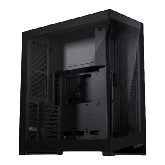
INTRODUCTION INTRODUCING THE PHANTEKS The Phanteks NV7 is a showcase full-tower chassis with a clean look from every side. It is the first installment of the new NV series, which is focused on showcasing your hardware in a premium build-quality chassis. Performance is uncompromised with Ultra-Fine Mesh panels while providing a clean and stylish look with the nearly seamless tempered glass front and left side panels. -
Page 6: D-Rgb Lighting Effects
LIGHTING EFFECTS The Digital-RGB lighting can be easily MODES controlled with the 4 buttons on top of Solid the chassis: LIGHT WHITE MAGENTA PINK ORANGE GOLD YELLOW GREEN TEAL BLUE BLUE Rainbow Breathing CHANNEL SWITCH A/B Pixelate SPEED Wave COLOR MODE Two-Tone Fade... -
Page 7: Exploded View
EXPLODED VIEW PARTS Chassis Front glass panel Right side mesh panel Left glass panel Top panel Bottom fan bracket Side fan bracket Rear door Bottom dust filter Front I/O GPU Support Bracket Motherboard Cover D-RGB Cover Top I/O Rear Mesh Cover Airflow Cover... -
Page 8: Accessories
ACCESSORIES GPU SUPPORT BRACKET AIRFLOW COVER Included in accessory box 2x Included in accessory box SCREWS OTHER ACCESSORIES D-RGB Motherboard adapter cable Microfiber Cloth Zipties Manual SSD + MOTHERBOARD MOTHERBOARD ANTI-SAG BRACKET EXTRA RIGHT SIDE SCREW STAND-OFF THUMB SCREW PANEL SCREW PSU SCREW HDD LOCKING SCREW STAND-OFF REMOVAL... -
Page 9: Specifications
SPECIFICATIONS CASE SPECIFICATIONS INCLUDED ACCESSORIES Dimension (DxWxH) 532 x 253 x 586 mm / 20.9 x 10.0 x 23.1 in GPU Support Bracket Form Factor Full Tower Airflow Cover Materials Steel, Tempered Glass front and side panels Toolbox ATX, micro-ATX, mini-ITX, E-ATX (up to 277 mm Motherboard Support wide), SSI-CEB (up to 290 mm w/o cover ) CLEARANCE... -
Page 10: Remove External Panels
REMOVE EXTERNAL PANELS OPEN REAR PANEL REMOVE GLASS SIDE PANEL REMOVE GLASS FRONT PANEL LOOSEN REMOVE THUMB SCREW SCREW Open the rear door by pulling it from the Loosen the 2 thumb screws in the rear, Unscrew the 2 screws from the left side bottom right corner. - Page 11 REMOVE EXTERNAL PANELS REMOVE TOP PANEL REMOVE RIGHT SIDE PANEL REMOVE REAR DOOR LOOSEN REMOVE THUMB SCREW SCREW Loosen the 2 thumb screws of the top Remove the screw on the top and slide Optionally, remove the back door by panel in the rear.
-
Page 12: Remove Covers
REMOVE COVERS REMOVE D-RGB COVER REMOVE MOTHERBOARD COVER REMOVE 1. unscrew SCREW Slide the D-RGB cover to the front of the chassis to remove it. Remove the screw located on the right side of the chassis. Push the motherboard cover down to remove it. -
Page 13: Motherboard Installation
MOTHERBOARD INSTALLATION ALIGN MOTHERBOARD Align the motherboard with the screwholes on the chassis’ motherboard tray. SECURE MOTHERBOARD Secure the motherboard with 9x motherboard screws. PRO TIP Use the included stand-off tool to easily remove and re-install the motherboard stand-offs for other motherboard form-factors ATTENTION INSTALL... -
Page 14: Power Supply Installation
POWER SUPPLY INSTALLATION SECURE PSU INSERT PSU Insert the PSU from the right side of the chassis. Secure the PSU from the rear with 4x PSU screws. INSTALL PRO TIP PSU SCREW Attach all PSU cables first before installing the PSU into the chassis. -
Page 15: Fan & Radiator Positions
RADIATOR & FAN POSITIONS RADIATOR POSITIONS FAN POSITIONS Side: up to 360 Top: up to 360 Side: 4x 120 mm Top: 3x 120 mm Bottom: up to 360/280 Rear: up to 240 Bottom: 3x 120/140 mm Rear: 2x 120 mm up to 360 up to 360 up to 360... - Page 16 RECOMMENDED AIRFLOW CONFIGURATIONS AIR-COOLED CONFIGURATION WATER COOLED CONFIGURATION Side: Intake Top: Exhaust Side: Exhaust Top: Exhaust Bottom: Intake Rear: Exhaust Bottom: Intake Rear: Exhaust up to 360...
-
Page 17: Fan & Radiator Installation
FAN & RADIATOR INSTALLATION SIDE FAN/RADIATOR BRACKET REMOVE SCREW Remove the screw located on the top. PULL & TAKE OUT BRACKET Remove the bracket by pulling the handle at the top of the bracket and take REMOVE THUMB SCREW it out. INSTALL FANS/RADIATOR Install up to 4x 120 fans/360 radiator on the bracket. - Page 18 FAN & RADIATOR INSTALLATION BOTTOM FAN/RADIATOR BRACKET REMOVE BOTTOM BRACKET routing cut-outs Release the bracket by removing the rear thumb screw. Slide the bracket to the front to remove it. INSTALL FANS/RADIATOR Install up to 3x 120mm / 3x 140 mm fans and/or 280/360 radiator on to the REMOVE bracket.
- Page 19 FAN & RADIATOR INSTALLATION REAR FAN/RADIATOR POSITION The rear has space for up to 240 radiator radiator and 2x 120 fans. The fans can be installed in front of the rear panel while the routing cut-out radiator can be installed behind the rear panel.
-
Page 20: Airflow Configurations
FAN & RADIATOR INSTALLATION TOP FAN/RADIATOR POSITION routing cut-out INSTALL FANS/RADIATOR Up to 3x 120 fans/360 radiator can be directly installed into the top of the chassis. Fan cables can be routed through the cut-outs on the top. -
Page 21: Power Button & Led
POWER BUTTON AND LED CONNECT POWER BUTTON Connect the power switch module to the motherboard. power switch/power LED module power LED power switch motherboard header diagram... -
Page 22: Front I/O
FRONT I/O I/O INTERFACE • USB 3.1 GEN 2 TYPE-C (1x) • USB 3.0 TYPE-A (2x) • Headphone/microphone (1x) CONNECT I/O CABLES TO MOTHERBOARD CONNECT USB 3.1 GEN 2 TYPE-C CONNECT USB 3.0 TYPE-A USB 3.0 USB 3.1 GEN 2 TYPE-C USB 3.0 TYPE-A HD AUDIO CONNECT HD AUDIO... -
Page 23: Move Front I/O To Secondary Position
MOVE FRONT I/O TO SECONDARY LOCATION STEPS TO MOVE I/O TO THE REAR REMOVE BOTTOM FAN BRACKET Remove the bottom fan bracket. REMOVE SCREWS Unscrew 2x screws located inside the chassis. REMOVE INSTALL SCREW SCREW SLIDE I/O UNIT OUT Slide the I/O unit forward and remove it. PUSH OUT COVER Push the cover ,located on the rear bottom, up to remove it. -
Page 24: D-Rgb Cables
A channel B max 7A per channel, max 4A per port TO SATA PSU EXPAND WITH OTHER D-RGB PRODUCTS To Phanteks Digital-RGB products (JST connector) TO TOP IO PANEL CHANNEL A PORTS SYNC LIGHTING TO MOTHERBOARD (OPTIONAL) CHANNEL B PORTS The D-RGB to motherboard cable is included in the accessory box. -
Page 25: Installing Storage
INSTALLING STORAGE TOP DOOR STORAGE OPEN TOP DOOR Loosen the thumb screw to open the top door. INSTALL 2.5’’ DRIVES Install up to 2x 2.5’’ drives with 2x SSD screws per SSD. 2.5’’ DRIVE 2.5’’ DRIVE cable routing LOOSEN INSTALL THUMB SCREW SSD SCREW... - Page 26 INSTALLING STORAGE BOTTOM DOOR STORAGE OPEN BOTTOM DOOR OPTION B - 4X 2.5’’ OPTION C - 2X 3.5’’ Loosen the thumb screw to open the door. INSTALL DRIVES The bottom door can be used for one of the following storage options: 1x 3.5’’...
-
Page 27: Internal Cable Management
INTERNAL CABLE MANAGEMENT PSU CABLE MANAGEMENT The PSU cables can be routed like the image below for clean cable management. Open the top cover door to loop the CPU & MB cables to get rid of excessive cable length. Loop excessive cable length on the inside of the top cover door. -
Page 28: Installing Led Covers
INSTALLING LED COVERS INSTALL MOTHERBOARD COVER The motherboard cover can be installed in two ways: Option 1: Default Option 2: Reversed The first option covers a bit more of the cables attached to For the second option, the cover is installed in reversed position. the motherboard, and is a great fit for standard sized ATX This covers less of the motherboard and allows more clearance motherboards. - Page 29 INSTALLING LED COVERS INSTALL D-RGB COVER 3. secure with thumbscrew After choosing the preferred position, align the motherboard Slide the D-RGB cover to the rear of the chassis to install it. cover (1) and slide upwards (2). Secure it with the thumb screw through the right side of the chassis (3).
-
Page 30: Installing Gpu Support Bracket
INSTALLING GPU SUPPORT BRACKET (OPTIONAL) INSTALL BRACKET ADJUST HEIGHT ADJUST DEPTH Install the GPU support bracket on the Adjust to the correct height for your GPU Adjust the depth of the bracket to hold motherboard cover with 1x thumb screw. and use the thumb screw to secure it. -
Page 31: External Cable Management
EXTERNAL CABLE MANAGEMENT CABLE LANES VELCRO TIE COMB OR GROMMET External cables can be managed with the Use the velcro tie on the bottom to tie all There are two options for the cables to leave cable lanes behind the rear door. The left lane cables down to the chassis. -
Page 32: Support
Sie unter www.phanteks.com Pour les dernières informations sur le produit, le manuel, le service et la garantie, veuillez visiter www.phanteks.com Para obtener la información más reciente sobre el producto, manual, ser- vicio y garantía, visite www.phanteks.com 有关产品、 手册、 服务和保修的最新信息, 请访问 www.phanteks.com... - Page 33 4. When connecting external devices to your desktop PC, carefully plan how the wires will be placed. Protect any connected cables from being trod on or pinched, particularly at plugs, convenience receptacles, or the point where they exit from. Phanteks Taiwan Inc. Importer EU Importer US 11F., No.
- Page 34 FOLLOW US SOCIAL MEDIA Instagram Phanteks Facebook Phanteks YouTube Phanteks Twitter @phanteks...
Need help?
Do you have a question about the NV7 and is the answer not in the manual?
Questions and answers