Table of Contents
Advertisement
Quick Links
ALLEN+ROTH and logo design are trademarks or
registered trademarks of LF, LLC.
All rights reserved.
Serial Number:
Questions, problems, missing parts? Before returning to your retailer,
call our customer service department at 866-439-9800, 8 a.m. - 8 p.m.,
EST, Monday - Sunday. You can also contact us at partsplus@lowes.com.
SS23001
Purchase Date:
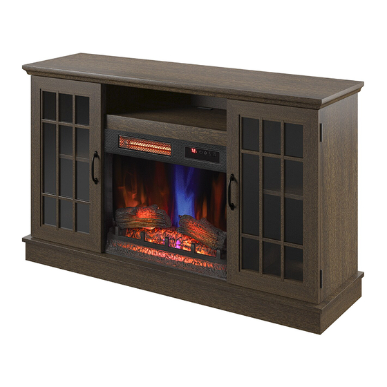
ITEM #3730311, 3735578
ELECTRIC FIREPLACE
MODEL # 144648/23MMP3101-PM93
MODEL # 144709/23MMP3101-TPO116
54 in
Español p. 31
Advertisement
Chapters
Table of Contents

Related Manuals for Allen + Roth 144648/23MMP3101-PM93


Summary of Contents for Allen + Roth 144648/23MMP3101-PM93
- Page 1 ITEM #3730311, 3735578 54 in ELECTRIC FIREPLACE MODEL # 144648/23MMP3101-PM93 ALLEN+ROTH and logo design are trademarks or MODEL # 144709/23MMP3101-TPO116 registered trademarks of LF, LLC. All rights reserved. Español p. 31 Serial Number: Purchase Date: Questions, problems, missing parts? Before returning to your retailer, call our customer service department at 866-439-9800, 8 a.m.
-
Page 2: Table Of Contents
TABLE OF CONTENTS Product Specifications ..........................2 Safety Information.............................3 Maximum Load............................Package Contents.............................6 Hardware Contents...........................8 Preparation.............................. Assembly Instructions..........................9 Operating Instructions..........................21 Troubleshooting............................. FCC/IC Information..........................25 Care and Maintenance..........................25 Warranty..............................Battery Replacement..........................27 Replacement Parts List......................... PRODUCT SPECIFICATIONS VOLTAGE 120VAC, 60 Hz AMPS 12.5 Amps WATTS 1500 Watts 23MMP3101REV1.0... -
Page 3: Safety Information
SAFETY INFORMATION When using electrical appliances, basic precautions should always be followed to reduce the risk of fire, electrical shock, and injury to persons including the following: 1. Read all instructions before using this appliance. 2. DANGER – High temperatures may be generated under certain abnormal conditions. Do not partially or fully cover or obstruct the front of this heater.CAUTION: Never leave the heater operating unattended. - Page 4 11. Do not insert or allow foreign objects to enter any ventilation or exhaust opening as this may cause an electric shock or fire, or damage the appliance. 12. To prevent a possible fire, do not block air intakes or exhaust in any manner. Do not use on soft surfaces, like a bed, where opening may become blocked.
-
Page 5: Maximum Load
MAXIMUM LOAD MAXIMUM LOAD 13.6 kg / 30 lb MAXIMUM LOAD 22.7 kg / 50 lb MAXIMUM LOAD 6.8 kg / 15 lb MAXIMUM LOAD 9.1 kg / 20 lb WARNING Loads heavier than the maximum weights specified may result in instability, causing tip over resulting in death or serious injury. -
Page 6: Package Contents
PACKAGE CONTENTS 23MMP3101REV1.0... - Page 7 PART DESCRIPTION QUANTITY Base Center Shelf Left Inside Panel Right Inside Panel Electric Fireplace Glass Panel Left Side Panel Top Panel Right Side Panel Side Back Panel Center Back Panel Left Door Right Door Electric Fireplace Back Panel Adjustable Shelf Center Front Rail Left Inside Rail Right Inside Rail...
-
Page 8: Hardware Contents
HARDWARE CONTENTS Note: USB to AC adapter is not in- cluded M3x12mm M3.5x12mm M4x50mm M3x12mm Screw Screw Screw Screw USB output Qty: 2 Qty:7 Qty: 8 Qty: 2 Qty: 1 M6.3x12mm M3x16mm Handle Screw Bolt Plastic Bracket Shelf Pin Qty: 2 Qty: 8 Qty: 4 Qty: 20... -
Page 9: Preparation
PREPARATION Before beginning assembly of product, make sure all parts are present. Compare parts with package contents list and hardware contents list. If any part is missing or damaged, do not attempt to assemble, install or operate the product. To protect the product from possible scratches, please assemble the parts on a scratch-free surface. - Page 10 ASSEMBLY INSTRUCTIONS 3.Attaching the Left and Right Inside Panel • Attach the Right Inside Rail (U) to the Right Inside Panel (R), inserting the pre-installed screws on the Right Inside Panel (R) into the pre-drilled holes on the Right Inside Rail (U). •...
- Page 11 ASSEMBLY INSTRUCTIONS 5. Securing the surround brackets • Find the pre-attached metal plate bracket behind the top surround rail. Rotate the bracket to span the joint of the top surround rail and side surround rail. • Secure the surround bracket with a Screw (AA). •...
- Page 12 ASSEMBLY INSTRUCTIONS 7. Installing mounting bolts for fireplace • Partially screw mounting Bolts (HH) into the Cen- ter Shelf (B). Leave approximately a 1/8" gap to place the heater as shown in step 6. Hardware Used M6.3x12mm Bolt 8. Attaching the insert brackets •...
- Page 13 ASSEMBLY INSTRUCTIONS 10. Placing the glass front • Turn the unit over so that Control Panel is now facing upward. • Locate the Electric Fireplace Glass Panel (E). • Carefully insert the Electric Fireplace Glass Panel (E) into the grooves of the surround rails as shown. Slide all the way in until the glass meets the bottom of the Control Panel.
- Page 14 ASSEMBLY INSTRUCTIONS 13. Assembling the base • Locate the Base (O) and place upside down on a flat surface. Attach the assembled base rails from step 11 to the bottom of the Base (O) by tightening the fasteners with a Phillips screwdriver.
- Page 15 ASSEMBLY INSTRUCTIONS 16. Installing the USB port • Carefully turn the unit so that it is sitting upright on a flat surface. • Slide the USB output (EE) through the opening in the center shelf. • Carefully secure the USB output (EE) in place using Screws (DD) and a Phillips screwdriver.
- Page 16 ASSEMBLY INSTRUCTIONS 19. Attaching the cabinet doors • Lift the Left Door (K) and align the hinges with the pre-attached hardware on the main assembly as shown. • Slide the barrel of the hinge on the door downward onto the pin of the hardware on the main assembly.
- Page 17 ASSEMBLY INSTRUCTIONS 22. Securing the back panels • Place the Back Panel Brackets (II) between the back panels and the grooves of the assembly as shown. • Fasten each Back Panel Bracket (II) using Screws (JJ). Repeat until all brackets are in place as indicated by the diagram.
- Page 18 ASSEMBLY INSTRUCTIONS 25. Assembling the fireplace • Place the assembled log set into the back of the unit behind the glass panel. • Push the tabs beneath the log set into the holes on the bottom panel. 26. Securing the log set •...
- Page 19 ASSEMBLY INSTRUCTIONS 28. Placing the fireplace background • Locate the Electric Fireplace Back Panel (M). • Only slightly bend the wallpaper and fit it into the back of the fireplace. • Note: this back panel is reversible and can be placed with either side facing the fireplace insert for a customizable look.
- Page 20 ASSEMBLY INSTRUCTIONS 31. Installing the tip restraint hardware • When the Tipping Restraint Hardware (KK) is properly installed, it can provide protection against unexpected tipping of the Unit due to small tremors, bumps or climbing. • Each Tipping Restraint Hardware (KK) includes one Unit Anchor, one Wall Anchor, one Anchor Tether, and four Anchor Screws.
-
Page 21: Operating Instructions
OPERATING INSTRUCTIONS CONTROL PANEL LOCATION ICON DESCRIPTION FUNCTION The POWER button supplies power to all the functions of the heater. Pressing the POWER button again will put the heater in standby mode. POWER Holding the Power button on the control panel for 10 seconds will disable the heater function. - Page 22 OPERATING INSTRUCTIONS FUNCTION ICON DESCRIPTION The up and down buttons “ ” on the remote TEMPERATURE IN- will increase / decrease temperature setting. CREASE / DECREASE The thermostat setting range is 62°F - 82°F ( 17°C - 27°C) or continuously ON. The thermostat is adjustable by 2°F or 1°C increments.
-
Page 23: Troubleshooting
TROUBLESHOOTING PROBLEM POSSIBLE CAUSE CORRECTIVE ACTION Unplug the fireplace, remove the back panel of the heater box and check that the The thermostat sensor is thermostat is plugged into the main circuit Display shows “ ” broken or disconnected. board. If this does not solve the problem contact customer service for a replace- ment thermostat sensor. - Page 24 TROUBLESHOOTING PROBLEM POSSIBLE CAUSE CORRECTIVE ACTION Thermostat setting is Adjust the temperature settings to ensure Heater does not blow preventing heater from that the thermostat is set higher than the warm air. turning on. current room temperature. Flame effect works but heat- With the power on press and hold the er function does not and the POWER button on the control panel...
-
Page 25: Fcc/Ic Information
FCC/IC INFORMATION Warning: Changes or modifications to this unit not expressly approved by the party responsible for compliance could void user’s authority to operate the equipment. NOTE: This equipment has been tested and found to comply with the limits for Class B digital device, pursuant to part 15 of the FCC Rules. -
Page 26: Warranty
1-YEAR LIMITED WARRANTY The manufacturer warrants that your new Electric Fireplace is free from manufacturing and material defects for a period of one year from date of purchase, subject to the following conditions and limitations. 1. Install and operate this appliance in accordance with the installation and operating instructions furnished with the product at all times. -
Page 27: Replacing The Remote Control Battery
REPLACING THE REMOTE CONTROL BATTERY: NOTE: Battery disposal Please always dispose of batteries at a suitable recycling point. CR2025 CR2025 CAUTION: • Do not ingest battery. • Non-rechargeable battery is not to be recharged. • Battery is to be inserted with the correct polarity. •... -
Page 28: Replacement Parts List
REPLACEMENT PARTS LIST For replacement parts, call our customer service department at 866-439-9800, 8 a.m. - 8 p.m., EST, Monday - Sunday. You could also contact us at partsplus@lowes.com . Part Part Name Part Number Thermostat Sensor Y21-S307-P186 Blower/ Heater Assembly Y21-S307-P01 Main Circuit Board Y21-S307-P15... - Page 29 Printed in Vietnam 23MMP3101REV1.0...
- Page 31 ARTÍCULO #3730311, 3735578 137,16 cm CHIMENEA ELÉCTRICA MODELO #144648/23MMP3101-PM93 ALLEN+ROTH y el diseño del logotipo son MODELO #144709/23MMP3101-TPO116 marcas comerciales o marcas registradas de LF, LLC. Todos los derechos reservados. Inglés p. 1 Número de serie: Fecha de compra: ¿Preguntas, problemas, piezas faltantes? Antes de volver a la tienda, llame a nuestro Departamento de Servicio al Cliente al 1-866-439-9800, de lunes a domingo de 8 a.m.
-
Page 32: Especificaciones Del Producto
ÍNDICE Especificaciones del producto......................32 Información de seguridad........................33 Carga máxima.............................35 Contenido del paquete........................36 Aditamentos..........................38 Preparación............................39 Instrucciones de ensamblaje........................39 Instrucciones de funcionamiento......................51 Solución de problemas.........................53 Información sobre la FCC/IC........................55 Cuidado y mantenimiento........................55 Garantía .......................... -
Page 33: Información Sobre Seguridad
INFORMACIÓN SOBRE SEGURIDAD Cuando utilice electrodomésticos eléctricos, siempre tome medidas de precaución básicas para evitar incendios, descargas eléctricas y lesiones personales. Entre las medidas: 1. Lea todas las instrucciones antes de usar este electrodoméstico. 2. PELIGRO: se pueden generar altas temperaturas debido a ciertas condiciones que no son normales. - Page 34 No introduzca objetos extraños ni permita que estos entren en las aberturas de ventilación o escape, ya que podrían provocar descargas eléctricas, incendios o daños en el electrodoméstico. Para evitar incendios, no bloquee las entradas ni salidas de aire de ninguna manera. No use el producto sobre superficies blandas, como una cama, donde las aberturas se puedan bloquear.
-
Page 35: Carga Máxima
CARGA MÁXIMA CARGA MÁXIMA: 13,6 kg / 30 lb CARGA MÁXIMA: 22,67 kg / 50 lb CARGA MÁXIMA: 6,8 kg / 15 lb CARGA MÁXIMA: 9,07 kg / 20 lb ADVERTENCIA Las cargas más pesadas que la capacidad máxima especificada pueden causar inestabilidad, lo que provoca vuelcos que pueden causar la muerte o lesiones graves. -
Page 36: Contenido Del Paquete
CONTENIDO DEL PAQUETE 23MMP3101REV1.0... - Page 37 PIEZA DESCRIPCIÓN CANTIDAD Base Estante central Panel interior izquierdo Panel interior derecho Panel de vidrio de la chimenea eléctrica Panel lateral izquierdo Panel superior Panel lateral derecho Panel posterior lateral Panel posterior central Puerta izquierda Puerta derecha Panel posterior de la chimenea eléctrica Estante ajustable Riel de estante central Riel de estante izquierdo...
-
Page 38: Aditamentos
ADITAMENTOS Nota: no se incluye el adaptador USB a CA Tornillo Tornillo Tornillo Tornillo M3 x 12 mm M3 x 12 mm M3.5 x 12 mm M4 x 50 mm Salida USB Cant.: 2 Cant.: 2 Cant.: 7 Cant.: 8 Cant.: 1 Soporte Perno... -
Page 39: Preparación
PREPARACIÓN Antes de comenzar a ensamblar el producto, asegúrese de tener todas las piezas. Compare las piezas con la lista del contenido del paquete y la lista de aditamentos. No intente ensamblar, instalar ni utilizar el producto si alguna pieza falta o está dañadas. Para proteger el producto de posibles rayones, ensamble las piezas sobre una superficie que no produzca rayones. - Page 40 INSTRUCCIONES DE ENSAMBLAJE 3. Fijación del panel interior izquierdo y derecho • Fije el riel interior derecho (U) al panel interior derecho (R), insertando los tornillos preinstala- dos en el panel interior derecho (R) en los orifi- cios pretaladrados en el riel interior derecho (U). •...
- Page 41 INSTRUCCIONES DE ENSAMBLAJE 5. Fijación de los soportes envolventes • Ubique el soporte de la placa metálica preinsta- lada detrás del riel envolvente superior. Gire el soporte para que abarque la unión del riel envol- vente superior y el riel envolvente lateral. •...
- Page 42 INSTRUCCIONES DE ENSAMBLAJE 7. Instalación de los pernos de montaje para chimenea • Atornille parcialmente los pernos de montaje (HH) en el estante central (B). Deje un espacio de aproximadamente 3,17 mm para colocar el calentador como se muestra en el paso 6. Aditamentos utilizados Perno M6.3 x 12 mm...
- Page 43 INSTRUCCIONES DE ENSAMBLAJE 10. Colocación del vidrio frontal • Dé vuelta la unidad de modo que el panel de control quede ahora hacia arriba. • Ubique el panel de vidrio de la chimenea eléctrica (E). • Inserte con cuidado el panel de vidrio de la chimenea eléctrica (E) en las ranuras de los rieles envolventes, como se muestra.
- Page 44 INSTRUCCIONES DE ENSAMBLAJE 13. Ensamblaje de la base • Ubique la base (O) y colóquela boca abajo sobre una superficie plana. Fije los rieles de la base ensamblados en el paso 11 a la parte inferior de la base (O) apretando los sujetadores con un destornillador Phillips.
- Page 45 INSTRUCCIONES DE ENSAMBLAJE 16. Instalación del puerto USB • Dé vuelta la unidad con cuidado para que quede en posición vertical sobre una superficie plana. • Deslice la salida USB (EE) a través de la abertura del estante central. • Asegure con cuidado la salida USB (EE) en su lu- gar con tornillos (DD) y un destornillador Phillips.
- Page 46 INSTRUCCIONES DE ENSAMBLAJE 19. Colocación de las puertas del gabinete • Levante la puerta izquierda (K) y alinee las bisagras con los aditamentos preinstalados en el ensamble principal, como se muestra. • Deslice el barril de la bisagra de la puerta hacia abajo sobre el pasador de los aditamentos en el ensamble principal.
- Page 47 INSTRUCCIONES DE ENSAMBLAJE 22. Fijación de los paneles posteriores • Coloque los soportes del panel posterior (II) entre los paneles posteriores y las ranuras del ensamble, como se muestra. • Fije cada soporte del panel posterior (II) con tornillos (JJ). Repita hasta que todos los soportes estén en su lugar, como se indica en el diagrama.
- Page 48 INSTRUCCIONES DE ENSAMBLAJE 25. Ensamblaje de la chimenea • Coloque el juego de leños ensamblado en la parte posterior de la unidad detrás del panel de vidrio. • Inserte las lengüetas debajo del juego de leños en los orificios del panel inferior. 26.
- Page 49 INSTRUCCIONES DE ENSAMBLAJE 28. Colocación del fondo de la chimenea • Ubique el panel posterior de la chimenea eléctrica (M). • Doble ligeramente el papel tapiz y colóquelo en la parte posterior de la chimenea. Nota: este panel posterior es reversible y se puede colocar con cualquiera de los lados hacia la unidad empotrable de la chimenea para conseguir una apariencia personalizable.
- Page 50 INSTRUCCIONES DE ENSAMBLAJE 31. Instalación de los aditamentos de contención antivuelcos • Cuando los aditamentos de contención antivuel- cos (KK) se instalan correctamente, pueden proporcionar protección contra vuelcos inespe- rados de la unidad debido a pequeños temblores, golpes o subidas. •...
-
Page 51: Instrucciones De Funcionamiento
INSTRUCCIONES DE FUNCIONAMIENTO UBICACIÓN DEL PANEL DE CONTROL FUNCIÓN ÍCONO DESCRIPCIÓN El botón de ENCENDIDO suministra alimentación a todas las funciones del calentador. Si presiona el botón de ENCENDIDO nuevamente, el calentador entrará en el modo de espera. POTENCIA Si mantiene presionado el botón de alimentación del panel de control durante 10 segundos, desactivará... - Page 52 INSTRUCCIONES DE FUNCIONAMIENTO FUNCIÓN ÍCONO DESCRIPCIÓN Antes de que el calentador se apague, el ventilador seguirá TIEMPO DE ENFRIAMIENTO funcionando durante un tiempo para enfriar las piezas internas. Al presionar el botón del temporizador se alternará entre los TEMPORIZADOR ajustes del temporizador: 30 minutos, 1 hora, 2 h, 3 h, 4 h, 5 h, 6 h, 7 h, 8 h, 9 h y APAGADO (00).
-
Page 53: Solución De Problemas
SOLUCIÓN DE PROBLEMAS PROBLEMA CAUSA POSIBLE ACCIÓN CORRECTIVA Desenchufe la chimenea, retire el panel posterior de la caja del calentador y re- vise que el termostato esté enchufado en El sensor del termostato La pantalla muestra “ ” la placa del circuito principal. Si esto no está... - Page 54 SOLUCIÓN DE PROBLEMAS PROBLEMA CAUSA POSIBLE ACCIÓN CORRECTIVA El funcionamiento normal continuará en ejecución durante menos de un minuto El calentador no emite aire Tiempo de enfriamiento. antes de apagarse. Los tiempos variarán caliente. dependiendo de las temperaturas. Durante este tiempo soplará aire frío. Verifique que la unidad esté...
-
Page 55: Información Sobre La Fcc/Ic
INFORMACIÓN SOBRE LA FCC/IC Advertencia: los cambios o las modificaciones a esta unidad que no estén expresamente aprobados por la parte responsable del cumplimiento podrían anular la autorización del usuario para utilizar el equipo. NOTA: este equipo ha sido probado y se ha verificado que cumple con los límites para un dispositivo digital clase B, conforme a la sección 15 de las regulaciones de la FCC. -
Page 56: Año De Garantía Limitada
1 AÑO DE GARANTÍA LIMITADA El fabricante garantiza que su nueva chimenea eléctrica no presentará defectos de fabricación ni en los materiales durante un período de un año a partir de la fecha de compra, siempre y cuando se cumplan las siguientes condiciones y limitaciones. 1. -
Page 57: Reemplazo De La Batería
CÓMO REEMPLAZAR LAS BATERÍAS DEL CONTROL REMOTO: NOTA: eliminación de las baterías Siempre elimine las baterías en un punto de reciclaje adecuado. CR2025 CR2025 PRECAUCIÓN: • No ingiera las batería. • La batería no es recargable y no debe recargarse. •... -
Page 58: Lista De Piezas De Repuesto
LISTA DE PIEZAS DE REPUESTO Para obtener piezas de repuesto, llame a nuestro Departamento de Servicio al Cliente al 1-866-439-9800, de lunes a domingo de 8 a.m. a 8 p.m., hora estándar del Este. También puede ponerse en contacto con nosotros en partsplus@lowes.com. Pieza Nombre de la pieza CANT. - Page 59 Impreso en Vietnam 23MMP3101REV1.0...
Need help?
Do you have a question about the 144648/23MMP3101-PM93 and is the answer not in the manual?
Questions and answers
We order new blower motor but can’t seem to get it wired up to work can you help