Advertisement
®
allen + roth
is a registered trademark of LF,
LLC. All rights reserved.
ATTACH YOUR RECEIPT HERE
Serial Number__________________ Purchase Date__________________
Questions, problems, missing parts? Before returning to your retailer, call our customer service
department at 1-866-439-9800, 8 a.m. - 8 p.m., EST, Monday - Sunday.
AR20048
welcoming
•
sophisticated
ELECTRIC FIREPLACE
1
•
inspiring
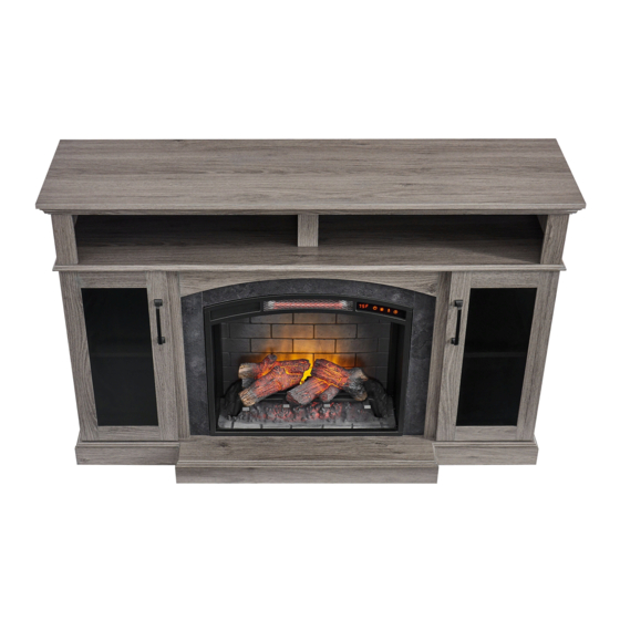
ITEM #2416659
TV STAND
MODEL #2360FM-24-259
Français p. 24
Español p. 47
Advertisement
Table of Contents

Subscribe to Our Youtube Channel
Related Manuals for Allen + Roth 2360FM-24-259


Summary of Contents for Allen + Roth 2360FM-24-259
- Page 1 • sophisticated • inspiring ITEM #2416659 ELECTRIC FIREPLACE ® allen + roth is a registered trademark of LF, LLC. All rights reserved. TV STAND MODEL #2360FM-24-259 Français p. 24 Español p. 47 ATTACH YOUR RECEIPT HERE Serial Number__________________ Purchase Date__________________ Questions, problems, missing parts? Before returning to your retailer, call our customer service department at 1-866-439-9800, 8 a.m.
-
Page 2: Table Of Contents
TABLE OF CONTENTS Package Contents ..........................3 Hardware Contents..........................4 Safety Information ..........................4 Preparation ............................7 Assembly Instructions.......................... 7 Operating Instructions ........................18 Care And Maintenance ........................20 Troubleshooting ..........................21 Warranty ............................22 Replacement Parts List ........................23... -
Page 3: Package Contents
PACKAGE CONTENTS PART DESCRIPTION QUANTITY PART DESCRIPTION QUANTITY Base Corner Panel Back Panel Partition Shelf Center Shelf Insert Center Front Panel Left Front Panel Left Wall Right Front Panel Right Wall Left Front Door Left Side Panel Right Front Door Right Side Panel Remote Control Center Back Panel... -
Page 4: Hardware Contents
HARDWARE CONTENTS (NOT SHOWN ACTUAL SIZE) PART DESCRIPTION QUANTITY Wooden Dowel Short Screw Locknut Connecting Rod Long Screw Back Panel Screws Shelf Pin Door Pull Touch-Up Pen SAFETY INFORMATION Please read and understand this entire manual before • Reorient or relocate the receiving antenna attempting to assemble, operate or install the product. - Page 5 SAFETY INFORMATION (CONT'D) • This appliance has hot and arcing or sparking parts Modifications not approved by the party responsible for compliance could void user’s authority to operate inside. DO NOT use it in areas where gasoline, the equipment. paint or flammable vapors or liquids are used or stored.
- Page 6 SAFETY INFORMATION (CONT'D) • To prevent a possible fire, DO NOT block air intakes Electrical Connection or exhaust in any manner. DO NOT use on soft • A 15-Amp, 120-volt, 60 Hz circuit with a properly surfaces, like a bed, where opening may become grounded outlet is required.
-
Page 7: Preparation
PREPARATION Before beginning assembly of product, make Estimated Assembly Time: 50 minutes sure all parts are present. Compare parts with Tools Required for Assembly (not included): package contents list and hardware contents list. If any part is missing or damaged, do not attempt Phillips screwdriver to assemble the product. - Page 8 ASSEMBLY INSTRUCTIONS (CONT’D) 3. Insert four wooden dowels (AA) into the holes on the back of the left front panel (O) and right front panel (P). Attach the left side panel (H) to the left front panel (O), secure with screwing three locknuts (CC) by Phillips screwdriver.
- Page 9 ASSEMBLY INSTRUCTIONS (CONT’D) 5. Insert two wooden dowels (AA) into outer holes on right side of base (K). Align and attach right wall (G), securing from underneath with two long screws (EE). Repeat for left wall (F). Hardware Used Wooden Dowel Long Screw 6.
- Page 10 ASSEMBLY INSTRUCTIONS (CONT’D) 7. Insert two wooden dowels (AA) into the top outer holes on both left wall (F), left side panel (H), right side panel (I) and right wall (G). Attach center shelf (D), secure with screwing ten locknuts (CC) by Phillips screwdriver. Hardware Used Wooden Dowel Locknut...
- Page 11 ASSEMBLY INSTRUCTIONS (CONT’D) 9. Insert two wooden dowels (AA) into holes on left side of center shelf (D). Attach corner panel (B), secure with screwing four locknuts (CC) by Phillips screwdriver. Repeat for remaining corner panel (B). Hardware Used Wooden Dowel Locknut 10.
- Page 12 ASSEMBLY INSTRUCTIONS (CONT’D) 11. Screw six connecting rods (DD) into designated plastic bushings on the back of the top (A). Fully tighten with a Phillips screwdriver. Hardware Used Connecting Rod 12. Insert wooden dowels (AA) into the top outer holes of corner panel (B) and partition (C). Attach top (A), secure with screwing six locknuts (CC) by Phillips screwdriver.
- Page 13 ASSEMBLY INSTRUCTIONS (CONT’D) 13. From behind the assembly, attach back panel (L) to shelving areas using back panel screws (FF). Repeat for remaining back panel (L). Hardware Used Back Panel Screw x 20 14. From behind the assembly, attach center back panel (J) to shelving areas using back panel screws (FF).
- Page 14 ASSEMBLY INSTRUCTIONS (CONT’D) 15. Insert shelf pins (GG) at desired height, ensuring they are level. Place shelf (M) on top of shelf pins (GG). Repeat for remaining the shelf (M). Hardware Used Shelf Pin 16. Place door pull (HH) into predrilled hole on right door, securing with two door pull bolt.
- Page 15 ASSEMBLY INSTRUCTIONS (CONT’D) 17. Install the doors I. Loosen the screws on the hinge arms and plates pre-attached on the walls (F and G). II. Pick up left front door (Q) and attach it to left wall (F) by engaging both door hinges simultaneously.
- Page 16 ASSEMBLY INSTRUCTIONS (CONT’D) 19. From behind the assembly, remove the preassembled insert brackets from the middle area. Save brackets and screws for future use. Note: Before proceeding to the next step, with the help of another person, move the mantel close to the final desired location.
- Page 17 ASSEMBLY INSTRUCTIONS (CONT’D) 21. Re-attach insert brackets with previously removed screws to secure insert (N). Assembly is now complete. With the help of another person, move the assembly to the final desired location. Once in final position you may plug the insert (N) into the power outlet.
-
Page 18: Operating Instructions
OPERATING INSTRUCTIONS Control Panel Remote Control To use the remote control, first insert two AAA batteries (included) into the remote control. Ensure the polarities of the batteries match the inside of the battery compartment. Note: The control panel is a touch screen. It will appear black. Touch the control panel once to “wake up” the controls. - Page 19 OPERATING INSTRUCTIONS (CONT’D) Timer Function • Press the TIMER ICON to set the countdown for the unit’s main power. • If the unit is powered OFF, you can press the TIMER ICON to power ON the unit. The ember bed will glow at the lowest brightness setting unless a different setting was saved in the memory.
-
Page 20: Care And Maintenance
CARE AND MAINTENANCE • Make sure the unit is turned OFF, unplugged and the heating elements of heater are cool whenever you are cleaning the heater or fireplace. • Clean the metal trim using a water-dampened soft, clean cloth. DO NOT use brass polish or household cleaners as these products will damage the metal trim. -
Page 21: Troubleshooting
TROUBLESHOOTING PROBLEM POSSIBLE CAUSE CORRECTIVE ACTION Error E1 displayed on The overheat sensor has Unplug unit, wait 15-20 minutes, then the sensor will reset control panel. been engaged. itself. Plug the unit back in and turn on the heater. If the problem persists, call customer service. -
Page 22: Warranty
ONE-YEAR LIMITED WARRANTY The manufacturer warrants that your new electric fireplace is free from manufacturing and material defects for a period of one year from date of purchase, subject to the following conditions and limitations. Install and operate this electric fireplace in accordance with the installation and operating instructions furnished with the product at all times. -
Page 23: Replacement Parts List
Right Front Door PH-2360FM-24-259-003 Remote Control PU17-23-RC PH-2360FM-24-259- KD Hardware Pack HARDWARE PACK Hinge PU-2360FM-005 Leveler T-1007 Printed in Vietnam Insert Mounting Bracket INSERT-SIDE-MB (With Screws) ® allen + roth is a registered trademark of LF, LLC. All Rights Reserved.
Need help?
Do you have a question about the 2360FM-24-259 and is the answer not in the manual?
Questions and answers