Table of Contents
Advertisement
Available languages
Available languages
ALLEN + ROTH and logo design are trademarks or
registered trademarks of LF, LLC. All rights reserved.
ATTACH YOUR RECEIPT HERE
Serial Number__________________ Purchase Date__________________
Questions, problems, missing parts? Before returning to your retailer, call our customer service
department at 866-439-9800, 8 a.m. - 8 p.m., EST, Monday - Sunday.
You could also contact us at partsplus@lowes.com or visit www.lowespartsplus.com.
SM21324
welcoming
•
sophisticated
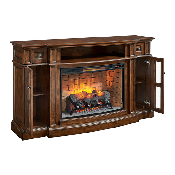
ELECTRIC FIREPLACE
MEDIA MANTEL
1
•
inspiring
ITEM #3747828
MODEL #3317FM-33-202
Español p. 25
Advertisement
Chapters
Table of Contents

Related Manuals for Allen + Roth 3317FM-33-202


Summary of Contents for Allen + Roth 3317FM-33-202
- Page 1 • sophisticated • inspiring ITEM #3747828 ELECTRIC FIREPLACE ALLEN + ROTH and logo design are trademarks or registered trademarks of LF, LLC. All rights reserved. MEDIA MANTEL MODEL #3317FM-33-202 Español p. 25 ATTACH YOUR RECEIPT HERE Serial Number__________________ Purchase Date__________________ Questions, problems, missing parts? Before returning to your retailer, call our customer service department at 866-439-9800, 8 a.m.
-
Page 2: Table Of Contents
TABLE OF CONTENTS Package Contents ..........................3 Hardware Contents..........................4 Safety Information ..........................4 Preparation ............................8 Assembly Instructions.......................... 8 Change Door Panels (Optional) ......................18 Operating Instructions ........................19 Care And Maintenance ........................21 Troubleshooting ..........................22 One-Year Limited Warranty ....................... 23 Replacement Parts List ........................ -
Page 3: Package Contents
PACKAGE CONTENTS PART DESCRIPTION QUANTITY PART DESCRIPTION QUANTITY Base Center Panel Wood Door Panel Left Middle Wall Fireplace Brick Wall Fireplace Brick Bottom Right Middle Wall Wall Left Outer Wall Fireplace Glass Front Right Outer Wall Front Trim Left Door (with hinges) Fire Log Right Door (with hinges) Fireplace Grate... -
Page 4: Hardware Contents
HARDWARE CONTENTS (NOT SHOWN ACTUAL SIZE) PART DESCRIPTION QUANTITY Long Bolt Washer Wooden Dowel Back Panel Screw Shelf Pin L-Bracket Screw Touch-up Pen SAFETY INFORMATION Please read and understand this entire manual before • Reorient or relocate the receiving antenna attempting to assemble, operate or install the product. - Page 5 SAFETY INFORMATION (CONTINUED) Modifications not approved by the party responsible • DO NOT route cord under furniture or appliances. for compliance could void user’s authority to operate Arrange cord away from traffic areas and where it the equipment. will not be tripped over. •...
- Page 6 SAFETY INFORMATION (CONTINUED) • To avoid electric shock, fire, or injury, review the • To disconnect this appliance, turn controls to the assembly instruction to confirm that the appropriate OFF position, then remove plug from outlet. critical components and accessories are being used •...
- Page 7 SAFETY INFORMATION (CONTINUED) Electrical Connection Grounding Instructions • A 15-Amp, 120-volt, 60 Hz circuit with a properly • This heater is for use on 120 volt. The cord has a grounded outlet is required. Preferably, the fireplace plug as shown below. See illustration or grounding will be on a dedicated circuit as other appliances instruction.
-
Page 8: Preparation
PREPARATION Before beginning assembly of product, make Estimated Assembly Time: 50 minutes sure all parts are present. Compare parts with package contents list and hardware contents list. Tools Required for Assembly (not included): If any part is missing or damaged, do not attempt Phillips screwdriver to assemble the product. - Page 9 ASSEMBLY INSTRUCTIONS (CONTINUED) 3. Align the dowels in center panel (B) to left middle wall (C) and right middle wall (D). Insert dowels into predrilled holes and press tight. Securing the left middle wall (C) and right middle wall (D) with four washers (BB) and four long bolts (AA).
- Page 10 ASSEMBLY INSTRUCTIONS (CONTINUED) 5. Place fireplace brick bottom wall (N) onto base (K), secure with four washers (BB) and four long bolts (AA). Hardware Used Long Bolt Washer 6. Insert two wooden dowels (CC) into outer holes on right side of base (K). Attach right outer wall (F), securing with two washers (BB) and two long bolts (AA).
- Page 11 ASSEMBLY INSTRUCTIONS (CONTINUED) 7. Insert two wooden dowels (CC) into the top outer holes on left outer wall (E), left middle wall (C), right middle wall (D) and right outer wall (F). Attach top (A), securing from underneath with ten washers (BB) and ten long bolts (AA).
- Page 12 ASSEMBLY INSTRUCTIONS (CONTINUED) 9. Attach the fireplace glass front (O), lowering it into the front groove on front trim (P). Secure the Glass by turning the pre-assembled plastic knobs. 10. Place the fireplace grate (R) by matching the bottom pins into the holes on the fireplace brick bottom wall (N).
- Page 13 ASSEMBLY INSTRUCTIONS (CONTINUED) 11. Remove the film from the adhesive on the top of the fireplace grate (R) and place the fire log (Q) on the center of the fireplace grate (R). Attach the USB cable from the heater into the USB port behind the fireplace grate (R).
- Page 14 ASSEMBLY INSTRUCTIONS (CONTINUED) 13. Insert the fireplace brick wall (M) into the mantel, slotting it into the grooves on base (K). Secure it by using two screws (GG) into the L-bracket (FF). Hardware Used Screw 14. Insert shelf pins (EE) at desired height, ensuring they are level.
- Page 15 ASSEMBLY INSTRUCTIONS (CONTINUED) 15. Install the doors I. Loosen the screws on the hinge arms and plates pre-attached on the walls (E and F). II. Pick up left door (G) and attach it to left outer wall (E) by engaging both door hinges simultaneously.
- Page 16 ASSEMBLY INSTRUCTIONS (CONTINUED) 16. If you need to adjust the doors, do so in the following manner. To adjust door up or down, loosen screws (a) on both hinges, adjust door, and retighten screws. To adjust door left or right, turn screws (b) on both hinges, in and out. To adjust door in or out, loosen screws (c) on both hinges, adjust door, and retighten screws.
- Page 17 ASSEMBLY INSTRUCTIONS (CONTINUED) 18. To reinstall drawer, slide glide roller (on track inside top) to front of top (A). Carefully align drawer box glide track (attached to sides of drawer box) with glide track (attached to inside of top). Making sure drawer is aligned and centered onto glides, gently push drawer.
-
Page 18: Change Door Panels (Optional)
CHANGE DOOR PANELS (OPTIONAL) The pre-installed glass door panels can be switched out with the included wood door panels (L). 1. Remove the silicone trim along the outer edges of the glass panel on the inside of the door. Start at a corner and pull to remove the four pieces. -
Page 19: Operating Instructions
OPERATING INSTRUCTIONS Control Panel Remote Control To use the remote control, first remove the plastic tab by gently pulling it out of remote control. Controls and Display The control panel will display the heater setting when the unit power is turned ON. Whichever control icon you press will display the current setting of the corresponding function. - Page 20 OPERATING INSTRUCTIONS (CONTINUED) Heater Function • Press the HEATER ICON to display the current heater setting. • Press the HEATER ICON again to scroll down through the heater settings. Note: Long-hold the icon to quickly scroll through settings. • Set the heater to “HI” (High) to have the heater run continually. •...
-
Page 21: Care And Maintenance
CARE AND MAINTENANCE • Make sure the unit is turned OFF, unplugged and the heating elements of heater are cool whenever you are cleaning the heater or fireplace. • Clean the metal trim using a water-dampened soft, clean cloth. DO NOT use brass polish or household cleaners as these products will damage the metal trim. -
Page 22: Troubleshooting
TROUBLESHOOTING PROBLEM POSSIBLE CAUSE CORRECTIVE ACTION Error E1 displayed on The overheat sensor has Unplug unit, wait 15-20 minutes, then the sensor will reset control panel. been engaged. itself. Plug the unit back in and turn on the heater. If the problem persists, call customer service. -
Page 23: One-Year Limited Warranty
ONE-YEAR LIMITED WARRANTY The manufacturer warrants that your new electric fireplace is free from manufacturing and material defects for a period of one year from date of purchase, subject to the following conditions and limitations. Install and operate this electric fireplace in accordance with the installation and operating instructions furnished with the product at all times. -
Page 24: Replacement Parts List
RC-HE85EL01 Heater KDI-02-26C Hardware Pack PU17-3317FM-HARDWARE PACK Knob PU17-2317FM-KNOB Glass Clips PU17-3317FM-GLASS CLIPS Printed in Vietnam Drawer Glide PU17-1317FM-GLIDES Hinge PU-2317FM-005 ALLEN + ROTH and logo design are trademarks Leveler T-1007 or registered trademark of LF, LLC. All rights reserved. - Page 25 LF, LLC. Todos los derechos reservados. ELÉCTRICA PARA SISTEMA DE AUDIO Y TV MODELO #3317FM-33-202 ADJUNTE SU RECIBO AQUÍ Número de serie __________________ Fecha de compra__________________ ¿Preguntas, problemas, piezas faltantes? Antes de volver a la tienda, llame a nuestro Departamento de Servicio al Cliente al 866-439-9800, de lunes a domingo de 8 a.m.
- Page 26 ÍNDICE Contenido del paquete ........................27 Aditamentos............................28 Información de seguridad ........................28 Preparación ............................32 Instrucciones de ensamblaje ......................32 Cambio de los paneles de puertas (opcional) ................... 42 Instrucciones de funcionamiento ....................... 43 Cuidado y mantenimiento ........................45 Solución de problemas ........................
-
Page 27: Contenido Del Paquete
CONTENIDO DEL PAQUETE PIEZA DESCRIPCIÓN CANTIDAD PIEZA DESCRIPCIÓN CANTIDAD Parte superior Base Panel de puerta de Panel central madera Pared del medio Pared de ladrillos de la izquierda chimenea Pared del medio Pared inferior de derecha ladrillos de la chimenea Pared exterior Parte frontal del vidrio izquierda... -
Page 28: Aditamentos
ADITAMENTOS (NO SE MUESTRAN EN TAMAÑO REAL) PIEZA DESCRIPCIÓN CANTIDAD Perno largo Arandela Espiga de madera Tornillo del panel posterior Pasador de repisa Soporte en L Tornillo Aplicador de retoque INFORMACIÓN DE SEGURIDAD Lea y comprenda completamente este manual antes •... - Page 29 INFORMACIÓN DE SEGURIDAD (CONTINUACIÓN) Las modificaciones que no estén aprobadas por la • NO pase el cable debajo de alfombras. NO cubra parte responsable del cumplimiento podrían anular la el cable con alfombras de pasillo, tapetes u objetos autorización del usuario para utilizar el equipo. similares.
- Page 30 INFORMACIÓN DE SEGURIDAD (CONTINUACIÓN) • Cada superficie prevista para soportar una carga • “ADVERTENCIA: la colocación de equipos de audio debe tener una declaración correspondiente en las y/o video en muebles no diseñados específicamente instrucciones de uso que indica la carga máxima en para soportar tales equipos puede causar la muerte libras (kilogramos) prevista para esa superficie.
- Page 31 INFORMACIÓN DE SEGURIDAD (CONTINUACIÓN) Conexión eléctrica Instrucciones de puesta a tierra • Se requiere un circuito de 15 amperios, 120 voltios, • Este calentador se diseñó para usarse con 60 Hz con un un tomacorriente con la debida puesta 120 voltios. El cable tiene un enchufe como se a tierra.
-
Page 32: Preparación
PREPARACIÓN Antes de empezar a ensamblar el producto, Tiempo estimado de ensamblaje: 50 minutos asegúrese de que todas las piezas estén Herramientas necesarias para el ensamblaje presentes. Compare las piezas con la lista del (no se incluyen): destornillador Phillips contenido del paquete y de los aditamentos. No intente ensamblar, instalar o usar el producto si faltan piezas o si están dañadas. - Page 33 INSTRUCCIONES DE ENSAMBLAJE (CONTINUACIÓN) 3. Alinee las espigas del panel central (B) con la pared central izquierda (C) y la pared central derecha (D). Inserte las espigas en los orificios pretaladrados y presione con fuerza. Asegure la pared central izquierda (C) y la pared central derecha (D) con cuatro arandelas (BB) y cuatro pernos largos (AA).
- Page 34 INSTRUCCIONES DE ENSAMBLAJE (CONTINUACIÓN) 5. Coloque la pared inferior de ladrillos de la chimenea (N) sobre la base (K) y asegúrela con cuatro arandelas (BB) y cuatro pernos largos (AA). Aditamentos utilizados Perno largo Arandela 6. Coloque dos espigas de madera (CC) en los orificios exteriores del lado derecho de la base (K).
- Page 35 INSTRUCCIONES DE ENSAMBLAJE (CONTINUACIÓN) 7. Coloque dos espigas de madera (CC) en los orificios exteriores superiores de la pared exterior izquierda (E), la pared del medio izquierda (C), la Pared del medio derecha (D) y la pared exterior derecha (F). Fije la parte superior (A) y asegure desde abajo con diez arandelas (BB) y diez pernos largos (AA).
- Page 36 INSTRUCCIONES DE ENSAMBLAJE (CONTINUACIÓN) 9. Coloque el vidrio frontal de la chimenea (O), bajándolo en la ranura frontal de la moldura frontal (P). Asegure el vidrio mediante el giro de las perillas plásticas preensambladas. 10. Coloque la rejilla de la chimenea (R) haciendo coincidir los pasadores inferiores en los orificios de la pared inferior de ladrillos de la chimenea (N).
- Page 37 INSTRUCCIONES DE ENSAMBLAJE (CONTINUACIÓN) 11. Retire la película del adhesivo en la parte superior de la rejilla para chimenea (R) y coloque el leño para chimenea (Q) en el centro de la rejilla para chimenea (R). Conecte el cable USB del calentador al puerto USB detrás de la rejilla de la chimenea (R).
- Page 38 INSTRUCCIONES DE ENSAMBLAJE (CONTINUACIÓN) 13. Inserte la pared de ladrillos de la chimenea (M) en la repisa, introduciéndolo en las ranuras de la base (K). Fíjela con dos tornillos (GG) en el soporte en L (FF). Aditamentos utilizados Tornillo 14. Coloque los soportes para estante (EE) a la altura deseada y asegúrese de que estén nivelados.
- Page 39 INSTRUCCIONES DE ENSAMBLAJE (CONTINUACIÓN) 15. Instale las puertas I. Afloje los tornillos de los brazos de las bisagras y de las placas fijadas previamente en las paredes (E y F). II. Levante la puerta izquierda (G) y fíjela a la pared exterior izquierda (E) al enganchar ambas bisagras de la puerta simultáneamente.
- Page 40 INSTRUCCIONES DE ENSAMBLAJE (CONTINUACIÓN) 16. Si necesita ajustar las puertas, hágalo de la siguiente manera. Para ajustar las puertas hacia arriba o hacia abajo, afloje los tornillos (a) de ambas bisagras, ajuste la puerta y vuelva a apretar los tornillos. Para ajustar la puerta hacia la derecha o hacia la izquierda, gire los tornillos (b) en ambas bisagras hacia dentro y afuera.
- Page 41 INSTRUCCIONES DE ENSAMBLAJE (CONTINUACIÓN) 18. Para volver a instalar la gaveta, deslice el rodillo deslizante (en la parte superior interna del riel) hacia la parte delantera de la cubierta (A). Alinee con cuidado el riel deslizante de la caja de la gaveta (unida a los lados de la caja de la gaveta) con el riel deslizante (fijado al interior de la cubierta).
-
Page 42: Cambio De Los Paneles De Puertas (Opcional)
CAMBIO DE LOS PANELES DE PUERTAS (OPCIONAL) Los paneles de puerta de vidrio preinstalados se pueden cambiar con los paneles de puerta de madera (L) incluidos. 1. Retire la moldura de silicona de los bordes exteriores del panel de vidrio en el interior de la puerta. -
Page 43: Instrucciones De Funcionamiento
INSTRUCCIONES DE FUNCIONAMIENTO Panel de control Control remoto Para utilizar el control remoto, primero retire la lengüeta plástica. Para ello retírela jalándola suavemente hacia afuera del control remoto. Controles y pantalla El panel de control mostrará la configuración del calentador cuando la unidad esté encendida. El icono de control que presione mostrará... - Page 44 INSTRUCCIONES DE FUNCIONAMIENTO (CONTINUACIÓN) Función de calentador • Presione el ICONO DE CALENTADOR para mostrar la configuración actual del calentador. • Presione el ICONO DEL CALENTADOR nuevamente para desplazarse hacia abajo a través de la configuración del calentador. Nota: mantenga presionado el icono para desplazarse rápidamente por la configuración. •...
-
Page 45: Cuidado Y Mantenimiento
CUIDADO Y MANTENIMIENTO • Asegúrese de que la unidad esté APAGADA, desenchufada y que los elementos de calefacción estén fríos cada vez que limpie el calentador o la chimenea. • Limpie el borde metálico con un paño suave y limpio humedecido con agua. NO use pulidores de latón ni limpiadores domésticos, ya que estos productos dañarán el borde metálico. -
Page 46: Solución De Problemas
SOLUCIÓN DE PROBLEMAS PROBLEMA CAUSA POSIBLE ACCIÓN CORRECTIVA El error E1 se muestra Se ha activado el sensor Desenchufe la unidad, espere de 15 a 20 minutos, luego el en el panel de control. de sobrecalentamiento. sensor se reiniciará automáticamente. Vuelva a enchufar la unidad y encienda el calentador. -
Page 47: Un Año De Garantía Limitada
UN AÑO DE GARANTÍA LIMITADA El fabricante garantiza que su nueva chimenea eléctrica no presentará defectos de fabricación ni en los materiales durante un período de un año a partir de la fecha de compra, siempre y cuando se cumplan las siguientes condiciones y limitaciones. Instale y use el la chimenea eléctrica según lo indican las instrucciones de instalación y funcionamiento provistas con el producto en todo momento. -
Page 48: Lista De Piezas De Repuesto
Perilla PU17-2317FM-KNOB Sujetadores de vidrio PU17-3317FM-GLASS CLIPS Impreso en Vietnam Riel de la gaveta PU17-1317FM-GLIDES Bisagras PU-2317FM-005 ALLEN + ROTH y el diseño del logotipo Nivelador T-1007 son marcas comerciales o marcas registradas de LF, LLC. Todos los derechos reservados.
Need help?
Do you have a question about the 3317FM-33-202 and is the answer not in the manual?
Questions and answers
Remote stoped working replaced the battery and could not find a receiver I have model number KDI-02-26C SN # 3-C2-A5-B1-0789
To troubleshoot the Allen + Roth remote model KDI-02-26C after replacing the battery, follow these steps:
1. Ensure the new battery is a CR2025 lithium battery and is inserted correctly, matching the + and - sides with the battery compartment markings.
2. Check if the remote is within range—stay within 20 feet and 45 degrees from the front of the fireplace insert.
3. Press the buttons slowly and steadily to ensure the transmitter recognizes the request.
4. If the remote signal is weak or intermittent, verify that the battery is not weak or failing.
5. If issues persist, try another new CR2025 battery to rule out a defective one.
6. If the remote still does not work, consult a qualified technician or the manufacturer for further assistance.
This answer is automatically generated
Insert quit. I need a repair or replacement