Advertisement
allen + roth
is a registered trademark of
®
LF, LLC. All rights reserved.
Questions, problems, missing parts? Before returning to your retailer, call our
customer service department at 1-866-439-9800, 8 a.m. - 8 p.m., EST, Monday - Friday.
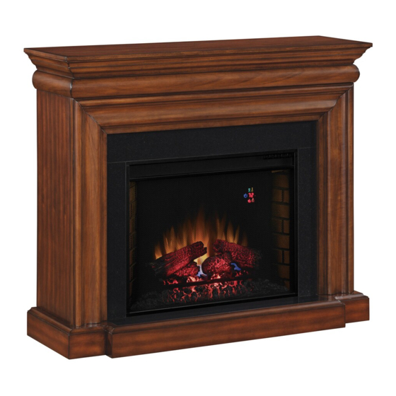
ELECTRIC FIREPLACE
MODEL #76246/28WM1838-C270
1
ITEM #0386381
Français p. 14
Español p. 27
Advertisement
Table of Contents

Related Manuals for Allen + Roth 76246


Summary of Contents for Allen + Roth 76246
- Page 1 ITEM #0386381 ELECTRIC FIREPLACE MODEL #76246/28WM1838-C270 allen + roth is a registered trademark of ® LF, LLC. All rights reserved. Français p. 14 Español p. 27 Questions, problems, missing parts? Before returning to your retailer, call our customer service department at 1-866-439-9800, 8 a.m. - 8 p.m., EST, Monday - Friday.
-
Page 2: Table Of Contents
TABLE OF CONTENTS Product Specifications ......................... 2 Safety Information ..........................3 Package Contents ..........................6 Hardware Contents..........................7 Preparation ............................7 Assembly Instructions........................... 8 Operating Instructions ........................10 Care and Maintenance ........................10 Troubleshooting ...........................11 Warranty ............................. 12 Replacement Parts List ........................13 PRODUCT SPECIFICATIONS VOLTAGE 120 V, 60 Hz... -
Page 3: Safety Information
SAFETY INFORMATION Please read and understand this entire manual before attempting to assemble, operate or install the product. WARNING • Before assembly, carefully use scissors or utility knife to cut and unwrap all parts. Make sure you do not discard the hardware. CAUTION •... - Page 4 SAFETY INFORMATION 17. Do not insert or allow foreign objects to enter any ventilation or exhaust opening as this may cause an electric shock or fire, or damage the appliance. 18. To prevent a possible fire, do not block air intakes or exhaust in any manner. Do not use on soft surfaces, like a bed, where opening may become blocked.
- Page 5 SAFETY INFORMATION WARNING: Make sure the power is turned off before proceeding. Any electrical repairs or rewiring of this unit should be carried out by a licensed electrician in accordance with national and local codes. If repairing or replacing any electrical component or wiring, the original wire routing, color coding and securing locations must be followed.
-
Page 6: Package Contents
PACKAGE CONTENTS Part Description Quantity Hearth/Base Left Front Panel Right Front Panel Center Front Panel Center Top Panel Left Side Panel Right Side Panel Mantel/Top Insert Remote Control... -
Page 7: Hardware Contents
HARDWARE CONTENTS (shown actual size) Washer Qty: 26 Wood Dowel Bolt Qty: 24 Qty: 26 Touch-up Pen Model No. W3304 (Not actual size) Qty: 1 PREPARATION Before beginning assembly of product, make sure all parts are present. Compare parts with package contents list and diagram above. -
Page 8: Assembly Instructions
ASSEMBLY INSTRUCTIONS 1. Set center front panel (D), right front panel (C) and left front panel (B) face down on a scratch-free surface. Insert one wood dowel (CC) into each of the pre- drilled holes on right front panel (C) and left front panel (B), then push the two pieces to fit snugly on center front panel (D). - Page 9 4. Insert one wood dowel (CC) into each of the pre-drilled holes on hearth/base (A). Attach left side panel (F) and right side panel (G) to the hearth-base (A). Insert the bolts (AA) and washers (BB) through the pre-drilled holes in the mounting blocks to secure the assembly.
-
Page 10: Operating Instructions
OPERATING INSTRUCTIONS Control panel can be accessed at upper-right corner of insert (I). - POWER The power button supplies power to all of the functions of the fireplace. The power button will put the insert (I) in a standby mode. This will turn off all functions at once but will hold the settings in the memory. By pressing the power button again the unit will turn on at the same settings. -
Page 11: Troubleshooting
REPLACING THE REMOTE CONTROL BATTERY When the remote control (J) stops operating or its range seems reduced, it is time to replace the battery with a new one. Note: Batteries should be removed if the product is to be left unused for a long time. 1. -
Page 12: Warranty
1-YEAR LIMITED WARRANTY The manufacturer warrants this product to be free from manufacturing and material defects for a period of one year from date of purchase, subject to the following conditions and limitations. 1. Install and operate this item in accordance with the installation and operating instructions furnished with the product at all times. -
Page 13: Replacement Parts List
REPLACEMENT PARTS LIST For replacement parts, call our customer service department at 1-866-439-9800, 8 a.m. - 8 p.m., EST, Monday - Friday. Part No. Part Description 28EF023SRA Control Panel - 5 Buttons Y10-C45-P32 Decorative Brick Panels Y10-S54-P17 Heater/Blower Assembly Y06-C26-P01 Control Panel Circuit Board Y10-C45-P32 Main Circuit Board...
Need help?
Do you have a question about the 76246 and is the answer not in the manual?
Questions and answers