Table of Contents
Advertisement
Available languages
Available languages
Quick Links
ALLEN+ROTH and logo design are trademarks or
registered trademarks of LF, LLC.
All rights reserved.
Serial Number:
Questions, problems, missing parts? Before returning to your retailer,
call our customer service department at 1-866-439-9800, 8 a.m. - 8 p.m.,
EST, Monday - Sunday. You can also contact us at partsplus@lowes.com.
AS21003
Purchase Date:
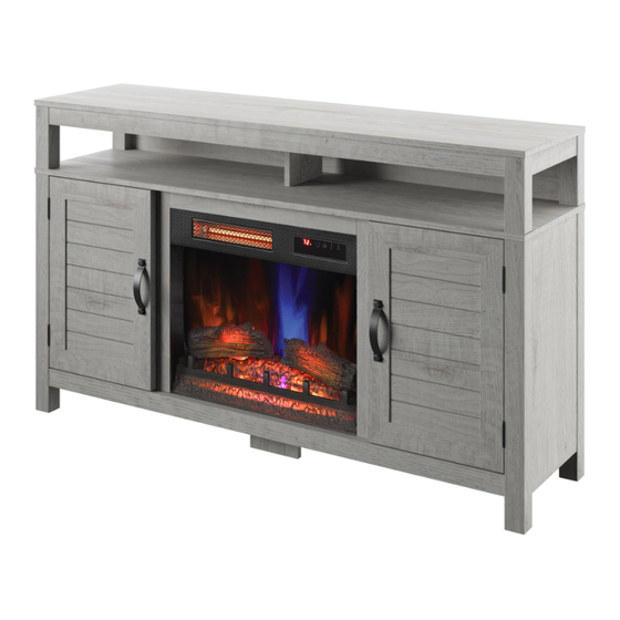
ELECTRIC FIREPLACE
MEDIA MANTEL
MODEL #147328/23MM7522-PD23
ITEM #3730312
Español p. 29
Advertisement
Chapters
Table of Contents

Related Manuals for Allen + Roth 147328/23MM7522-PD23


Summary of Contents for Allen + Roth 147328/23MM7522-PD23
- Page 1 ITEM #3730312 ELECTRIC FIREPLACE MEDIA MANTEL ALLEN+ROTH and logo design are trademarks or MODEL #147328/23MM7522-PD23 registered trademarks of LF, LLC. All rights reserved. Español p. 29 Serial Number: Purchase Date: Questions, problems, missing parts? Before returning to your retailer, call our customer service department at 1-866-439-9800, 8 a.m. - 8 p.m., EST, Monday - Sunday.
-
Page 2: Table Of Contents
TABLE OF CONTENTS Product Specifi cations ......................2 Safety Information........................3 Maximum Load.........................5 Package Contents........................6 Hardware Contents........................8 Preparation..........................10 Assembly Instructions......................10 Operating Instructions......................21 Troubleshooting........................23 FCC/IC Information.........................25 Care and Maintenance......................25 Warranty..........................26 Battery Replacement......................27 Replacement Parts List......................PRODUCT SPECIFICATIONS VOLTAGE 120VAC, 60 Hz AMPS 12.5 Amps WATTS 1500 Watts... -
Page 3: Safety Information
SAFETY INFORMATION When using electrical appliances, basic precautions should always be followed to reduce the risk of fi re, electrical shock, and injury to persons including the following: 1. Read all instructions before using this appliance. 2. DANGER – High temperatures may be generated under certain abnormal conditions. - Page 4 Fig.1 12. Do not insert or allow foreign objects to enter any ventilation or exhaust opening as this may cause an electric shock or fi re, or damage the appliance. 13. To prevent a possible fi re, do not block air intakes or exhaust in any manner. Do not use on soft surfaces, like a bed, where opening may become blocked.
-
Page 5: Maximum Load
MAXIMUM LOAD MAXIMUM LOAD 22.7 kg / 50 lb MAXIMUM LOAD 27.3 kg / 60 lb MAXIMUM LOAD 6.8 kg / 15 lb MAXIMUM LOAD 9.1 kg / 20 lb WARNING Loads heavier than the maximum weights specifi ed may result in instability, causing tip over resulting in death or serious injury. -
Page 6: Package Contents
PACKAGE CONTENTS 23MM7522REV2.0... - Page 7 PACKAGE CONTENTS PART DESCRIPTION QUANTITY Base Top Surround Rail Left Partition Right Partition Glass Panel Left Side Panel Top Panel Right Side Panel Back Side Panels Upper Back Panel Left Door Right Door Front Top Post Back Left Top Post Back Right Top Post Upper Partition Fixed Shelf...
-
Page 8: Hardware Contents
HARDWARE CONTENTS 3x12mm 4x50mm 6.3x12mm 6.3x50mm 3.5x12mm Ø Ø Ø Ø Ø Screw Bolt Bolt Screw Screw Qty: 2 Qty:7 Qty: 6 Qty: 5 Qty: 8 3x16mm 6.3x25mm Tipping Restraint Ø10mm Ø16mm Ø Ø Spring Washer Washer Bolt Hardware Screw Qty: 8 Qty: 8 Qty: 4... -
Page 9: Preparation
PREPARATION Before beginning assembly of product, make sure all parts are present. Compare parts with package contents list and hardware contents list. If any part is missing or damaged, do not attempt to assemble, install or operate the product. To protect the product from possible scratches, please assemble the parts on a scratch-free surface. - Page 10 ASSEMBLY INSTRUCTIONS 3. Assembling the fi replace • Locate the Front Panel with Control Button (EA). • Using Screws (BB), secure the Front Panel with Control Button (EA) between the Left and Right Inside Panels and just below the Top Surround Rail as shown.
- Page 11 ASSEMBLY INSTRUCTIONS 6. Attaching the center foot • Locate the Base Bracket (T) and press against the bottom of the main assembly in the very center of the base as indicated. • Secure in place using a Bolt (DD). Hardware Used 6.3x12mm Ø...
- Page 12 ASSEMBLY INSTRUCTIONS 9. Attaching the door handles • Locate the Left and Right Doors (U and V). • Each Door Handle (MM) has pre-attached screws. Remove these screws and place handles over the pre-drilled holes in the Left Door (U). •...
- Page 13 ASSEMBLY INSTRUCTIONS 12. Attaching the media bay partition • Locate the Upper Partition (P). • Insert the pre-installed screws on the Upper Partition (P) into the pre-drilled holes on the Top Panel. • Secure the Upper Partition (P) in place by tightening the fasteners on the Top Panel with a Phillips screwdriver as shown 13.
- Page 14 ASSEMBLY INSTRUCTIONS 15. Securing the fi xed shelf • Insert Screws (CC) through the center of the Fixed Shelf and into the pre-drilled holes on the Upper Partition as shown. Tighten all Screws (CC) using a Phillips screwdriver. Hardware Used 4x50mm Ø...
- Page 15 ASSEMBLY INSTRUCTIONS 18. Connecting the top • To tighten fasters behind the fi replace surround, you will need to do so from the back of the unit. Secure both screws behind the top surround rail with a Phillips screwdriver. 19. Securing the back panels •...
- Page 16 ASSEMBLY INSTRUCTIONS 21. Attaching the insert brackets • Locate the Insert L Brackets (EF) and secure to each side of the Heater Box (EB) using Bolts (NN). Hardware Used 4x12mm Ø Bolt 22. Installing the fi replace heater • Rest the brackets of the Heater Box (EB) on the previously installed mounting bolts from step 15.
- Page 17 ASSEMBLY INSTRUCTIONS 24. Assembling the log set • Route the wires of the Logset Left (EC) and the Logset Right (ED) down the back of the Ember Bed (EG) and into the receiving tabs to secure in place. Refer to the lower diagram. •...
- Page 18 ASSEMBLY INSTRUCTIONS 27. Connecting the fi replace wiring • Connect Key Button Connection Wire to heater. • Insert the Ember Bed Connection Wire into the Key Button heater. Connection Wire • Route the Ember Bed Connection Wire down Ember Bed the side surround rail and along the back of Connection Wire the log set, securing it in place with the clips as...
- Page 19 ASSEMBLY INSTRUCTIONS 30. Installing the tip restraint hardware • When the Tipping Restraint Hardware (II) is properly installed, it can provide protection against unexpected tipping of the Unit due to small tremors, bumps or climbing. • Each Tipping Restraint Hardware (II) includes one Unit Anchor, one Wall Anchor, one Anchor Tether, and four Anchor Screws.
-
Page 20: Operating Instructions
OPERATING INSTRUCTIONS CONTROL PANEL LOCATION ICON FUNCTION DESCRIPTION There are 5 brightness levels that can be selected FLAME and OFF (00) setting. Settings F5 - F1 decrease in brightness. Press the heater button on the control panel to turn on/off (00) and adjust the heater setting. HEATER To change between °F and °C, press and hold the HEATER button on the control panel for 3 seconds. - Page 21 OPERATING INSTRUCTIONS ICON FUNCTION DESCRIPTION Pressing the timer button will cycle through the TIMER timer settings: 30 minutes, 1 Hour, 2H, 3H, 4H, 5H, 6H, 7H, 8H, 9H and OFF (00). The fl ame speed is only adjustable from the FLAME SPEED remote control.
-
Page 22: Troubleshooting
TROUBLESHOOTING PROBLEM POSSIBLE CAUSE CORRECTIVE ACTION Unplug the fi replace, remove the back panel of the heater box and check that The thermostat sensor is the thermostat is plugged into the main Display shows “ ” broken or disconnected. circuit board. If this does not solve the problem contact customer service for a replacement thermostat sensor. - Page 23 TROUBLESHOOTING PROBLEM POSSIBLE CAUSE CORRECTIVE ACTION Thermostat setting is Adjust the temperature settings to Heater does not blow preventing heater from ensure that the thermostat is set higher warm air. turning on. than the current room temperature. With the power on press and hold the Flame eff...
-
Page 24: Fcc/Ic Information
FCC/IC INFORMATION Warning: Changes or modifi cations to this unit not expressly approved by the party responsible for compliance could void user’s authority to operate the equipment. NOTE: This equipment has been tested and found to comply with the limits for Class B digital device, pursuant to part 15 of the FCC Rules. -
Page 25: Warranty
1-YEAR LIMITED WARRANTY The manufacturer warrants that your new Electric Fireplace is free from manufacturing and material defects for a period of one year from date of purchase, subject to the following conditions and limitations. Install and operate this appliance in accordance with the installation and operating instructions furnished with the product at all times. -
Page 26: Replacing The Remote Control Battery
REPLACING THE REMOTE CONTROL BATTERY: NOTE: Battery disposal Please always dispose of batteries at a suitable recycling point. 1pcs CR2025 included CAUTION: • Do not ingest battery. • Non-rechargeable battery is not to be recharged. • Battery is to be inserted with the correct polarity. •... -
Page 27: Replacement Parts List
REPLACEMENT PARTS LIST For replacement parts, call our customer service department at 1-866-439-9800, 8 a.m. - 8 p.m., EST, Monday - Sunday. You could also contact us at partsplus@lowes.com. PART PART NAME PART NUMBER Thermostat Sensor Y21-S307-P186 Blower/ Heater Assembly Y21-S307-P01 Main Circuit Board Y21-S307-P15... - Page 28 Printed in Vietnam 23MM7522REV2.0...
- Page 29 ARTÍCULO #3730312 REPSIA CON CHIMENEA ELÉCTRICA Y SISTEMA DE AUDIO Y TV ALLEN+ROTH y el diseño del logotipo son MODELO #147328/23MM7522-PD23 marcas comerciales o marcas registradas de LF, LLC. Todos los derechos reservados. Español p. 29 Número de serie: Fecha de compra: ¿Preguntas, problemas, piezas faltantes? Antes de volver a la tienda, llame a...
-
Page 30: Especifi Caciones Del Producto
ÍNDICE Especifi caciones del producto ....................30 Información de segurida......................31 Carga Máxima........................33 Contenido del paquete......................34 Aditamentos...........................36 Preparación..........................37 Instrucciones de ensamblaje....................37 Instrucciones de funcionamiento....................48 Solución de problemas......................50 Información sobre la FCC/IC....................52 Cuidado y mantenimiento......................52 Garantía..........................53 Reemplazo de la batería......................54 Lista de piezas de repuesto....................55 ESPECIFICACIONES DEL PRODUCTO VOLTAJE 120VAC, 60 Hz... -
Page 31: Información De Segurida
INFORMACIÓN DE SEGURIDAD Cuando utilice electrodomésticos eléctricos, siempre tome medidas de precaución básicas para evitar incendios, descargas eléctricas y lesiones personales. Entre las medidas: 1. Lea todas las instrucciones antes de usar este electrodoméstico. 2. PELIGRO: se pueden generar altas temperaturas debido a ciertas condiciones que no son normales. - Page 32 Fig.1 No introduzca objetos extraños ni permita que estos entren en las aberturas de ventilación o escape, ya que podrían provocar descargas eléctricas, incendios o daños en el electrodoméstico. Para evitar incendios, no bloquee las entradas ni salidas de aire de ninguna manera.
-
Page 33: Carga Máxima
CARGA MÁXIMA CARGA MÁXIMA 22,7 kg / 50 lb CARGA MÁXIMA 27,3 kg / 60 lb CARGA MÁXIMA 6,8 kg / 15 lb CARGA MÁXIMA 9,1 kg / 20 lb PRECAUCIÓN Cargas mayores que los pesos máximos especifi cados puede generar inestabilidad y, en consecuencia, desplomes que pueden causar la muerte o lesiones graves. -
Page 34: Contenido Del Paquete
CONTENIDO DEL PAQUETE 23MM7522REV2.0... - Page 35 CONTENIDO DEL PAQUETE PIEZA DESCRIPCIÓN CANTIDAD Base Riel envolvente superior Partición izquierda Partición derecha Panel de vidrio Panel lateral izquierdo Panel superior Panel lateral derecho Paneles laterales posteriores Panel posterior superior Puerta izquierda Puerta derecha Soporte superior delantero Soporte superior posterior izquierdo Soporte superior posterior derecho Partición superior Repisa fi...
-
Page 36: Aditamentos
ADITAMENTOS Tornillo de Perno de Tornillo de Perno de Tornillo de Ø4x50 mm Ø6,3x50 mm Ø3,5x12 mm Ø3x12 mm Ø6,3x12 mm Cant: 2 Cant:7 Cant: 6 Cant: 5 Cant: 8 Arandela de Arandela de Perno de Aditamento de Tornillo de resorte de Ø10 mm Ø3x16 mm... -
Page 37: Preparación
PREPARACIÓN Antes de comenzar a ensamblar el producto, asegúrese de tener todas las piezas. Compare las piezas con la lista del contenido del paquete y la lista de aditamentos. No intente en- samblar, instalar ni utilizar el producto si falta alguna pieza o si estas están dañadas. Para proteger el producto de posibles rayones, ensamble las piezas sobre una superfi... - Page 38 INSTRUCCIONES DE ENSAMBLAJE 3. Ensamblaje de la chimenea • Ubique el panel delantero con el botón de control (EA). • Con tornillos (BB), fi je el panel delantero con el botón de control (EA) entre los paneles inte- riores izquierdo y derecho, y justo debajo del riel envolvente superior, como se muestra.
- Page 39 INSTRUCCIONES DE ENSAMBLAJE 6. Colocación de la pata central • Ubique el soporte de la base (T) y presione contra la parte inferior del ensamble principal en el centro de la base, como se indica. • Asegúrelo en su lugar con un perno (DD). Aditamentos utilizados Perno de Ø6,3x12 mm...
- Page 40 INSTRUCCIONES DE ENSAMBLAJE 9. Colocación de las manijas de puerta • Ubique las puertas izquierda y derecha (U y V). • Cada manija de puerta (MM) tiene tornillos preinstalados. Retire estos tornillos y coloque las manijas sobre los orifi cios pretaladrados en la puerta izquierda (U).
- Page 41 INSTRUCCIONES DE ENSAMBLAJE 12.Conexión de la partición de la bahía para audio/TV • Ubique la partición superior (P). • Inserte los tornillos preinstalados en la partición superior (P) en los orifi cios pretaladrados en el panel superior. • Asegure la partición superior (P) en su lugar apretando los sujetadores en el panel superior con un destornillador Phillips, como se muestra.
- Page 42 INSTRUCCIONES DE ENSAMBLAJE 15. Fijación del estante fi jo • Inserte tornillos (CC) a través del centro del estante fi jo y en los orifi cios pretaladrados en la partición superior, como se muestra. Apriete todos los tornillos (CC) con un destornillador Phillips.
- Page 43 INSTRUCCIONES DE ENSAMBLAJE 18. Conexión de la parte superior • Para apretar los sujetadores detrás del contor- no de la chimenea, deberá hacerlo desde la parte posterior de la unidad. Asegure ambos tornillos detrás del riel envolvente superior con un destornillador Phillips. 19.
- Page 44 INSTRUCCIONES DE ENSAMBLAJE 21. Colocación de los soportes para accesorios • Ubique los soportes para accesorios (EF) y asegúrelos a cada lado de la caja de calenta- dor (EB) con pernos (NN). Aditamentos utilizados Perno de Ø4x12 mm 22. Instalación del calentador de la chimenea •...
- Page 45 INSTRUCCIONES DE ENSAMBLAJE 24. Ensamblaje del juego de leños • Enrute los cables del juego de leños izquierdo (EC) y el juego de leños derecho (ED) por la parte posterior del lecho de brasas (EG) y hacia las pestañas receptoras para asegurarlos en su lugar.
- Page 46 INSTRUCCIONES DE ENSAMBLAJE 27. Conexión del cableado de la chimenea • Conecte el cable de conexión del botón al calentador. Cable de conexión • Inserte el cable de conexión del lecho de bra- del botón sas en el calentador. Cable de conexión •...
- Page 47 INSTRUCCIONES DE ENSAMBLAJE 30. Instalación de los aditamentos de contención antivuelcos • Cuando los aditamentos de contención antivuelcos (II) se instalan correctamente, pueden proporcionar protección contra vuelcos inesperados de la unidad debido a pequeños temblores, golpes o subidas. • Cada aditamento de contención antivuelcos (II) incluye un ancla de la unidad, un ancla de pared, un amarre de ancla y cuatro tornillos de anclaje.
-
Page 48: Instrucciones De Funcionamiento
INSTRUCCIONES DE FUNCIONAMIENTO UBICACIÓN DEL PANEL DE CONTROL ICONO FUNCIÓN DESCRIPCIÓN Hay 5 niveles de brillo que se pueden seleccionar, además del ajuste APAGADO (00). Los ajustes F5 a LLAMA F1 disminuyen en brillo. Presione el botón del calentador en el panel de control para encender o apagar (00) y ajustar la CALENTADOR confi... - Page 49 INSTRUCCIONES DE FUNCIONAMIENTO ICONO FUNCIÓN DESCRIPCIÓN Al presionar el botón del temporizador se alternará TEMPORIZADOR entre los ajustes del temporizador: 30 minutos, 1 hora, 2 h, 3 h, 4 h, 5 h, 6 h, 7 h, 8 h, 9 h y APAGADO (00).
-
Page 50: Solución De Problemas
SOLUCIÓN DE PROBLEMAS PROBLEMA CAUSA POSIBLE ACCIÓN CORRECTIVA Desenchufe la chimenea, retire el pa- nel posterior de la caja del calentador y revise que el termostato esté enchu- El sensor del termostato fado en la placa del circuito principal. La pantalla muestra “ ”... - Page 51 SOLUCIÓN DE PROBLEMAS PROBLEMA CAUSA POSIBLE ACCIÓN CORRECTIVA El funcionamiento normal continuará en ejecución por menos de un minuto El calentador no emite aire antes de apagarse. Los tiempos Tiempo de enfriamiento. caliente. variarán dependiendo de las temperaturas. Durante este tiempo soplará...
-
Page 52: Información Sobre La Fcc/Ic
INFORMACIÓN SOBRE LA FCC/IC Advertencia: los cambios o las modifi caciones a esta unidad que no estén expresamente aprobados por la parte responsable del cumplimiento podrían anular la autorización del usuario para utilizar el equipo. NOTA: este equipo ha sido probado y se ha verifi cado que cumple con los límites para un dispositivo digital clase B, conforme a la sección 15 de las regulaciones de la FCC. -
Page 53: Año De Garantía Limitada
1 AÑO DE GARANTÍA LIMITADA El fabricante garantiza que su nueva chimenea eléctrica no presentará defectos de fabricación ni en los materiales durante un período de un año a partir de la fecha de compra, siempre y cuando se cumplan las siguientes condiciones y limitaciones. Este electrodoméstico se debe instalar y operar en todo momento de acuerdo con las instrucciones de instalación y operación proporcionadas con el producto. -
Page 54: Reemplazo De La Batería
CÓMO REEMPLAZAR LAS BATERÍAS DEL CONTROL REMOTO NOTA: eliminación de las NOTE: Battery disposal Please always dispose of batteries baterías. Siempre elimine at a suitable recycling point. las baterías en un punto de reciclaje adecuado. Se incluye 1 batería CR2025 PRECAUCIÓN: •... -
Page 55: Lista De Piezas De Repuesto
LISTA DE PIEZAS DE REPUESTO Para obtener piezas de repuesto, llame a nuestro Departamento de Servicio al Cliente al 1-866-439-9800, de lunes a domingo de 8 a.m. a 8 p.m., hora estándar del Este. También puede ponerse en contacto con nosotros en partsplus@lowes.com. PIEZA NOMBRE DE LA PIEZA NÚMERO DE PIEZA... - Page 56 Impreso en Vietnam 23MM7522REV2.0...
Need help?
Do you have a question about the 147328/23MM7522-PD23 and is the answer not in the manual?
Questions and answers