Table of Contents
Advertisement
Quick Links
ALLEN + ROTH and logo design are trademarks or
registered trademarks of LF, LLC. All rights reserved.
ATTACH YOUR RECEIPT HERE
Serial Number__________________ Purchase Date__________________
Questions, problems, missing parts? Before returning to your retailer, call our customer service
department at 866-439-9800, 8 a.m. - 8 p.m., EST, Monday - Sunday. You could also contact us at
partsplus@lowes.com.
XXXXXXX
welcoming
•
sophisticated
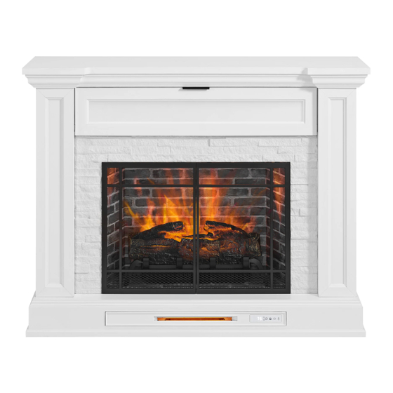
50.5-IN ELECTRIC
1
•
inspiring
ITEM #5228504
FIREPLACE
MODEL #2468FM-28-311
Español p. 24
Advertisement
Table of Contents

Related Manuals for Allen + Roth 2468FM-28-311


Summary of Contents for Allen + Roth 2468FM-28-311
- Page 1 • sophisticated • inspiring ITEM #5228504 50.5-IN ELECTRIC ALLEN + ROTH and logo design are trademarks or registered trademarks of LF, LLC. All rights reserved. FIREPLACE MODEL #2468FM-28-311 Español p. 24 ATTACH YOUR RECEIPT HERE Serial Number__________________ Purchase Date__________________ Questions, problems, missing parts? Before returning to your retailer, call our customer service department at 866-439-9800, 8 a.m.
-
Page 2: Table Of Contents
TABLE OF CONTENTS Package Contents ..........................3 Hardware Contents..........................4 Safety Information ..........................4 Preparation ............................8 Assembly Instructions.......................... 8 Change Door Panel (Optional) ......................16 Maximum Recommended Weight Loads ................... 17 Operating Instructions ........................18 Care And Maintenance ........................20 Troubleshooting .......................... -
Page 3: Package Contents
PACKAGE CONTENTS PART DESCRIPTION QUANTITY PART DESCRIPTION QUANTITY Left Opening Plate Center Shelf Fireplace Brick Wall Left Front Panel Fire Log Right Front Panel Fireplace Grate Left Side Panel Remote Control (Battery Inside) Right Side Panel Right Opening Plate Upper Opening Plate Base Center Panel Left Faux Metal Door... -
Page 4: Hardware Contents
HARDWARE CONTENTS (NOT SHOWN ACTUAL SIZE) PART DESCRIPTION QUANTITY PART DESCRIPTION QUANTITY Bolt Tip Restraint Hardware Washer Touch-up Pen Back Panel Mounting Hardware With Screw Pivot Hinge Screw Short Bolt Short Screw SAFETY INFORMATION Please read and understand this entire manual before •... - Page 5 SAFETY INFORMATION (CONTINUED) • DO NOT route cord under furniture or appliances. Modifications not approved by the party responsible Arrange cord away from traffic areas and where it for compliance could void user’s authority to operate the equipment. will not be tripped over. •...
- Page 6 SAFETY INFORMATION (CONTINUED) • To avoid electric shock, fire, or injury, review the • To disconnect this appliance, turn controls to the assembly instruction to confirm that the appropriate OFF position, then remove plug from outlet. critical components and accessories are being used •...
- Page 7 SAFETY INFORMATION (CONTINUED) Electrical Connection Grounding Instructions • A 15-Amp, 120-volt, 60 Hz circuit with a properly • This heater is for use on 120-volt. The cord has a grounded outlet is required. Preferably, the fireplace plug as shown below. See illustration or grounding will be on a dedicated circuit as other appliances instruction.
-
Page 8: Preparation
PREPARATION Before beginning assembly of product, make sure Estimated Assembly Time: 50 minutes all parts are present. Compare parts with package Tools Required for Assembly (not contents list and hardware contents list. If any part is missing or damaged, do not attempt to assemble the included): Phillips screwdriver product. - Page 9 ASSEMBLY INSTRUCTIONS (CONTINUED) 2. Insert the wood dowel and 2 lower plastic connectorson the upper opening plate (G) to the center shelf (B), tight the lock nut clock-wise to secure. 3. Attach the front panels (E, F) into the holes in the base (S).
- Page 10 ASSEMBLY INSTRUCTIONS (CONTINUED) 4. Tilt the side panels (E, F) slightly outwards and attach the center shelf (B). Make sure the side panels are pushed back to its vertical position to secure with the center shelf (B). 5. Secure the upper opening plate (G) to the left and right front panels (C.
- Page 11 ASSEMBLY INSTRUCTIONS (CONTINUED) 6. As shown in the diagram, insert the center back panel (J) along the grooves of the front panels (C, D). 7. Assemble the top (A) onto assembly from step 6 panel (E,F) and front panel (C,D). Turn the locking nut clockwise to secure with the top.
- Page 12 ASSEMBLY INSTRUCTIONS (CONTINUED) 8. Secure the center back panels (J) to the product using the back panel mounting hardware (CC), screwing the screws by Phillips screw driver (As shown in diagram 8). Hardware Used Back Panel Mounting Hardware With Screw 9.
- Page 13 ASSEMBLY INSTRUCTIONS (CONTINUED) 10. Place the freplace grate (N) by matching the bottom pins into the holes on the base (S).Slot the USB cable from the heater underneath through the cable hole on the base (S). Securing with two bolts (FF) by Phillips screw-driver.
- Page 14 ASSEMBLY INSTRUCTIONS (CONTINUED) 12. Insert the freplace brick wall (L) into the mantel from the back side, slotting it into the grooveson base (S). Secure it by using two screws (EE) into the L-bracket. Hardware Used Screw 13. Hold the flip down door (H) horizontally with the hinge side up, insert the pin of the left hinge to the plastic female thread on bottom left of the opening.
- Page 15 ASSEMBLY INSTRUCTIONS (CONTINUED) 14. Screw the 2 hydraulic rod to the door by twisting it clockwise to secure the flip down door. NOTE: Use the pre-assembled levelers on the base of the fireplace to level the unit. Twist the levelers counterclockwise to increase the height, twist the clockwise to decrease the height.
-
Page 16: Change Door Panel (Optional)
ASSEMBLY INSTRUCTIONS (CONTINUED) WARNING: You must install the tip restraint hardware to help prevent any accidents or damage to the unit. We strongly recommend attaching the tip restraint hardware to a wall stud Wall Stud and your unit. For all other wall types, please visit your local hardware store to obtain the proper hardware. -
Page 17: Maximum Recommended Weight Loads
ASSEMBLY INSTRUCTIONS (CONTINUED) FITS UP TO MOST 142.24 cm / 56 in FLAT PANEL TVS MAXIMUM LOAD 36,28 kg / 59 lb MAXIMUM LOAD 15.87 kg / 35 lb CAUTION: This console is intended for use with flat panel TV’s only. Do not exceed the maximum weights indicated. -
Page 18: Operating Instructions
OPERATING INSTRUCTIONS Control Panel Remote Control To use the remote control, first remove the plastic tab by gently pulling it out of remote control. Controls and Display The control panel will display the heater setting when the unit power is turned ON. Whichever control icon you press will display the current setting of the corresponding function. - Page 19 OPERATING INSTRUCTIONS (CONTINUED) Sleep Timer Function (Remote Control Only) • The Sleep TIMER function will set a countdown to shut down the unit’s main power. • Press the TIMER ICON to display the current Sleep Timer setting. • Press the TIMER ICON again to scroll through the timer settings, which are: 30 (minutes), 1H, 2H, 3H, 4H, 5H, 6H, 7H, 8H, 9H, OF (OFF).
-
Page 20: Care And Maintenance
CARE AND MAINTENANCE • Make sure the unit is turned OFF, unplugged and the heating elements of heater are cool whenever you are cleaning the heater or fireplace. • Clean the metal trim using a water-dampened soft, clean cloth. DO NOT use brass polish or household cleaners as these products will damage the metal trim. -
Page 21: Troubleshooting
TROUBLESHOOTING PROBLEM POSSIBLE CAUSE CORRECTIVE ACTION Error E1 displayed on The overheat sensor has Unplug unit, wait 15-20 minutes, then the sensor will reset control panel. been engaged. itself. Plug the unit back in and turn on the heater. If the problem persists, call customer service. -
Page 22: One-Year Limited Warranty
ONE-YEAR LIMITED WARRANTY The manufacturer warrants that your new electric fireplace is free from manufacturing and material defects for a period of one year from date of purchase, subject to the following conditions and limitations. Install and operate this electric fireplace in accordance with the installation and operating instructions furnished with the product at all times. -
Page 23: Replacement Parts List
128,27 CM CHIMENEA ELÉCTRICA ALLEN + ROTH and logo design are trademarks or registered trademarks of LF, LLC. All rights reserved. ALLEN+ROTH y el diseño del logotipo son marcas comerciales o marcas registradas de LF, LLC. Todos los derechos reservados.
Need help?
Do you have a question about the 2468FM-28-311 and is the answer not in the manual?
Questions and answers
Hi is it possible to order this item? Mine over heated and it’s not working, and I would. Like to replace it. YEH-KDI-28-FIRE GRATE,