Table of Contents
Advertisement
Available languages
Available languages
Quick Links
ALLEN + ROTH and logo design are trademarks or
registered trademarks of LF, LLC. All rights reserved.
ATTACH YOUR RECEIPT HERE
Serial Number__________________ Purchase Date__________________
Questions, problems, missing parts? Before returning to your retailer, call our customer service
department at 866-439-9800, 8 a.m. - 8 p.m., EST, Monday - Sunday. You could also contact us at
partsplus@lowes.com.
AS22224
welcoming
•
sophisticated
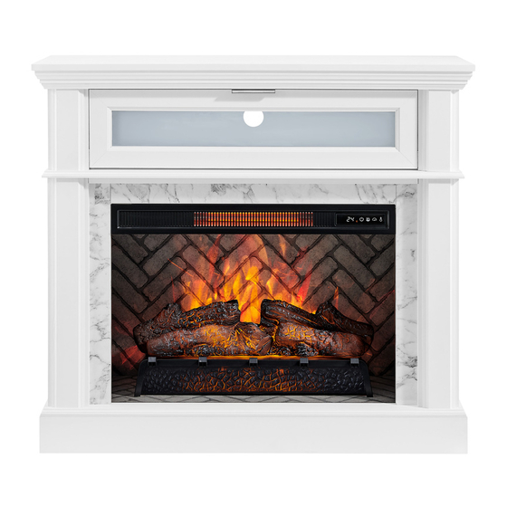
ELECTRIC FIREPLACE
MEDIA MANTEL FAUX
CARRARA MARBLE
1
•
inspiring
ITEM #1074762; 32255011
SURROUND
MODEL #1942FM-26-311
Français p. 23
Advertisement
Chapters
Table of Contents

Related Manuals for Allen + Roth 1942FM-26-311


Summary of Contents for Allen + Roth 1942FM-26-311
- Page 1 • sophisticated • inspiring ITEM #1074762; 32255011 ELECTRIC FIREPLACE ALLEN + ROTH and logo design are trademarks or registered trademarks of LF, LLC. All rights reserved. MEDIA MANTEL FAUX CARRARA MARBLE SURROUND MODEL #1942FM-26-311 Français p. 23 ATTACH YOUR RECEIPT HERE...
-
Page 2: Table Of Contents
TABLE OF CONTENTS Package Contents ..........................3 Hardware Contents..........................4 Safety Information ..........................4 Preparation ............................8 Assembly Instructions.......................... 8 Maximum Recommended Weight Loads ................... 16 Operating Instructions ........................17 Care And Maintenance ........................19 Troubleshooting ..........................20 One-Year Limited Warranty ....................... 21 Replacement Parts List ........................ -
Page 3: Package Contents
PACKAGE CONTENTS PART DESCRIPTION QUANTITY PART DESCRIPTION QUANTITY Fireplace Brick Wall Front Bar Fireplace Glass Front Insert Brace Base Left Wall Fire Log Right Wall Fireplace Grate Left Front Panel Remote Control (Battery Inside) Right Front Panel Heater... -
Page 4: Hardware Contents
HARDWARE CONTENTS (NOT SHOWN ACTUAL SIZE) PART DESCRIPTION QUANTITY PART DESCRIPTION QUANTITY Long Screw Washer Wooden Dowel Bolt Locknut Touch-up Pen Connecting Rod Screw Short Screw Tip Restraint Hardware L-Bracket Stopper SAFETY INFORMATION Please read and understand this entire manual before •... - Page 5 SAFETY INFORMATION (CONTINUED) • DO NOT route cord under furniture or appliances. Modifications not approved by the party responsible Arrange cord away from traffic areas and where it for compliance could void user’s authority to operate the equipment. will not be tripped over. •...
- Page 6 SAFETY INFORMATION (CONTINUED) • To avoid electric shock, fire, or injury, review the • To disconnect this appliance, turn controls to the assembly instruction to confirm that the appropriate OFF position, then remove plug from outlet. critical components and accessories are being used •...
- Page 7 SAFETY INFORMATION (CONTINUED) Electrical Connection Grounding Instructions • A 15-Amp, 120-volt, 60 Hz circuit with a properly • This heater is for use on 120-volt. The cord has a grounded outlet is required. Preferably, the fireplace plug as shown below. See illustration or grounding will be on a dedicated circuit as other appliances instruction.
-
Page 8: Preparation
PREPARATION Before beginning assembly of product, make sure Estimated Assembly Time: 50 minutes all parts are present. Compare parts with package Tools Required for Assembly (not contents list and hardware contents list. If any part is missing or damaged, do not attempt to assemble the included): Phillips screwdriver product. - Page 9 ASSEMBLY INSTRUCTIONS (CONTINUED) 2. Insert two wooden dowels (BB) into the holes on the back of the top (A). Align and attach front bar (B), secure with screwing two locknuts (CC) by Phillips screwdriver. Hardware Used Wooden Dowel Locknut 3. Insert four wooden dowels (BB) into the holes on the back of the top (A).
- Page 10 ASSEMBLY INSTRUCTIONS (CONTINUED) 4. Attach heater (P), secure with screwing four screws (JJ) by Phillips screwdriver. Hardware Used Screw 5. Screw four connecting rods (DD) into the holes on the back of the front panels (F,G). Hardware Used Connecting Rod...
- Page 11 ASSEMBLY INSTRUCTIONS (CONTINUED) 6. Insert four wooden dowels (BB) into the holes on the back of the left front panel (F) and right front panel (G). Attach the left wall (D) to the left front panel (F), secure with screwing two locknuts (CC) by Phillips screwdriver.
- Page 12 ASSEMBLY INSTRUCTIONS (CONTINUED) 8. Insert four wooden dowels (BB) into the holes on the back of the top (A). Place assembly from Step 6 onto top (A), secure with screwing six locknuts (CC) by Phillips screwdriver. Hardware Used Wooden Dowel Locknut 9.
- Page 13 ASSEMBLY INSTRUCTIONS (CONTINUED) 10. Insert eight wooden dowels (BB) into the bottom outer holes on both left wall (D), right wall (E), left front panel (F) and right front panel (G). Attach base (J), secure with screwing eight long screws (AA) by Phillips screwdriver. Hardware Used Long Screw Wooden Dowel...
- Page 14 ASSEMBLY INSTRUCTIONS (CONTINUED) 12. Remove the film from the adhesive on the top of the fireplace grate (N) and place the fire log (M) on the center of the fireplace grate (N). 13. Screw two L-bracket (FF) onto the fireplace brick wall (H) using four short screws (EE).
- Page 15 ASSEMBLY INSTRUCTIONS (CONTINUED) 14. Align the USB cable from behind through the cable hole on the fireplace brick wall (H). Attach the USB cable from the heater into the USB port behind the fireplace grate (N). Insert the fireplace brick wall (H) into the mantel, slotting it into the grooves on base (J).
-
Page 16: Maximum Recommended Weight Loads
ASSEMBLY INSTRUCTIONS (CONTINUED) WARNING: You must install the tip restraint hardware to help prevent any accidents or damage to the unit. We strongly recommend attaching the tip restraint hardware to a wall stud and your unit. Wall Stud For all other wall types, please visit your local hardware store to obtain the proper hardware. -
Page 17: Operating Instructions
OPERATING INSTRUCTIONS Control Panel Remote Control To use the remote control, first remove the plastic tab by gently pulling it out of remote control. Controls and Display The control panel will display the heater setting when the unit power is turned ON. Whichever control icon you press will display the current setting of the corresponding function. - Page 18 OPERATING INSTRUCTIONS (CONTINUED) Heater Function • Press the HEATER ICON to display the current heater setting. • Press the HEATER ICON again to scroll down through the heater settings. Note: Long-hold the icon to quickly scroll through settings. • Set the heater to “HI” (High) to have the heater run continually. •...
-
Page 19: Care And Maintenance
CARE AND MAINTENANCE • Make sure the unit is turned OFF, unplugged and the heating elements of heater are cool whenever you are cleaning the heater or fireplace. • Clean the metal trim using a water-dampened soft, clean cloth. DO NOT use brass polish or household cleaners as these products will damage the metal trim. -
Page 20: Troubleshooting
TROUBLESHOOTING PROBLEM POSSIBLE CAUSE CORRECTIVE ACTION Error E1 displayed on The overheat sensor has Unplug unit, wait 15-20 minutes, then the sensor will reset control panel. been engaged. itself. Plug the unit back in and turn on the heater. If the problem persists, call customer service. -
Page 21: One-Year Limited Warranty
ONE-YEAR LIMITED WARRANTY The manufacturer warrants that your new electric fireplace is free from manufacturing and material defects for a period of one year from date of purchase, subject to the following conditions and limitations. Install and operate this electric fireplace in accordance with the installation and operating instructions furnished with the product at all times. -
Page 22: Replacement Parts List
1942FM-26-311-INSERT BRACE Left Wall 1942FM-26-311-LEFT WALL Right Wall 1942FM-26-311-RIGHT WALL PF-1942FM-26-311-INSERT Insert Surround Set SURROUND SET Fireplace Brick Wall 1942FM-26-311-INSERT WALL BRICK Fireplace Glass Front 1942FM-26-GLASS FRONT Base 1942FM-26-311-BASE Fire Log FIRE LOG 2 Fireplace Grate GRATE B Remote Control... - Page 23 • sophistiqué • inspirant ARTICLE #1074762; 32255011 FOYER ÉLECTRIQUE ALLEN + ROTH et le logo sont des marques de commerce ou des marques de commerce déposées de LF, LLC. Tous droits réservés. AVEC MEUBLE MULTIMÉDIA CONTOUR EN FAUX MARBRE DE CARRARE MODÈLE #1942FM-26-311...
- Page 24 TABLE DES MATIÈRES Contenu de l’emballage ........................25 Quincaillerie incluse........................... 26 Consignes de sécurité ........................26 Préparation ............................30 Instructions pour l’assemblage ......................30 Charges maximales recommandées ....................38 Mode d’emploi ........................... 39 Entretien ............................41 Dépannage ............................42 Garantie limitée de un an ........................43 Liste des pièces de rechange ......................
-
Page 25: Contenu De L'emballage
CONTENU DE L’EMBALLAGE PIÈCE DESCRIPTION QUANTITÉ PIÈCE DESCRIPTION QUANTITÉ Dessus Mur de briques du foyer Barre avant Vitre avant du foyer Traverse Base Cloison gauche Bûche Cloison droite Grille du foyer Panneau avant gauche Télécommande (pile à l’intérieur) Panneau avant droit Radiateur... -
Page 26: Quincaillerie Incluse
QUINCAILLERIE INCLUSE (NON ILLUSTRÉE À LA GRANDEUR RÉELLE) PIÈCE DESCRIPTION QUANTITÉ PIÈCE DESCRIPTION QUANTITÉ Vis longue Rondelle Goujon en bois Boulon Contre-écrou Crayon à retouche Tige de jonction Dispositif anti- Vis courte renversement Support en L Butée CONSIGNES DE SÉCURITÉ Assurez-vous de lire et de comprendre l’intégralité... - Page 27 CONSIGNES DE SÉCURITÉ (SUITE) • NE placez PAS le cordon sous un tapis. Ne couvrez Les modifications non autorisées expressément par la PAS le cordon d’alimentation avec une carpette, un partie responsable de la conformité peuvent annuler le droit de l’utilisateur de se servir de cet appareil. tapis de couloir, ni tout autre article similaire.
- Page 28 CONSIGNES DE SÉCURITÉ (SUITE) • Chaque surface destinée à supporter une charge • « AVERTISSEMENT – Placer de l’équipement doit avoir une déclaration correspondante dans les audio ou vidéo sur des meubles qui ne sont pas instructions indiquant la charge maximale prévue spécialement conçus pour ce type d’équipement pour la surface en question.
- Page 29 CONSIGNES DE SÉCURITÉ (SUITE) Branchement électrique Instructions pour la mise à la terre • Un circuit de 15 A, 120 V, 60 Hz avec une prise • Ce radiateur est destiné à être utilisé à une tension correctement mise à la terre est nécessaire. de 120 volts.
-
Page 30: Préparation
PRÉPARATION Avant de commencer l’assemblage du produit, Temps d’assemblage approximatif : assurez-vous d’avoir toutes les pièces en main. 50 minutes. Comparez le contenu de l’emballage avec la liste Outils nécessaires pour l’assemblage de la quincaillerie incluse. S’il y a des pièces (non inclus) : tournevis cruciforme. - Page 31 INSTRUCTIONS POUR L’ASSEMBLAGE (SUITE) 2. Insérez deux goujons en bois (BB) dans les trous à l’arrière du plateau (A). Faites correspondre la barre avant (B) en la vissant avec deux contre-écrous (CC) à l’aide d’un tournevis cruciforme. Quincaillerie utilisée Goujon en bois Contre-écrou 3.
- Page 32 INSTRUCTIONS POUR L’ASSEMBLAGE (SUITE) 4. Fixez le radiateur (P) en le vissant avec quatre vis (JJ) à l’aide d’un tournevis cruciforme. Quincaillerie utilisée 5. Vissez quatre tiges de jonction (DD) dans les trous à l’arrière des panneaux avant (F et G). Quincaillerie utilisée Tige de jonction...
- Page 33 INSTRUCTIONS POUR L’ASSEMBLAGE (SUITE) 6. Insérez quatre goujons en bois (BB) dans les trous situés à l’arrière des panneaux avant gauche (F) et avant droit (G). Fixez la cloison gauche (D) au panneau avant gauche (F) en le vissant avec deux contre-écrous (CC) à l’aide d’un tournevis cruciforme.
- Page 34 INSTRUCTIONS POUR L’ASSEMBLAGE (SUITE) 8. Insérez quatre goujons en bois (BB) dans les trous à l’arrière du plateau (A). Placez la partie assemblée à l’étape 6 sur le plateau (A) et fixez-la en vissant six contre-écrous (CC) à l’aide d’un tournevis cruciforme. Quincaillerie utilisée Goujon en bois Contre-écrou...
- Page 35 INSTRUCTIONS POUR L’ASSEMBLAGE (SUITE) 10. Insérez huit goujons en bois (BB) dans les trous extérieurs de la partie inférieure de la cloison de gauche (D), de la cloison de droite (E), du panneau avant gauche (F) et du panneau avant droit (G). Fixez la base (J) en la vissant avec huit vis longues (AA) à...
- Page 36 INSTRUCTIONS POUR L’ASSEMBLAGE (SUITE) 12. Retirez la pellicule de l’adhésif sur le dessus de la grille du foyer (N) et placez la bûche (M) au centre de la grille du foyer (N). 13. Vissez deux supports en L (FF) sur le mur de briques du foyer (H) à...
- Page 37 INSTRUCTIONS POUR L’ASSEMBLAGE (SUITE) 14. Passez le câble USB par l’arrière à travers le trou pour câble sur le mur de briques du foyer (H). Branchez le câble USB du radiateur sur le port USB situé à l’arrière de la grille du foyer (N).
-
Page 38: Charges Maximales Recommandées
INSTRUCTIONS POUR L’ASSEMBLAGE (SUITE) AVERTISSEMENT : Vous devez installer le dispositif anti-renversement pour prévenir les accidents ou les dommages à l’unité. Nous vous recommandons fortement de fixer le dispositif anti-renversement à un Montant mural montant de cloison et à votre appareil. Pour fixer le dispositif sur tous les autres types de murs, veuillez vous rendre chez votre détaillant local pour obtenir la quincaillerie appropriée. -
Page 39: Mode D'emploi
MODE D’EMPLOI Panneau de commande Télécommande Pour utiliser la télécommande, enlevez d’abord la languette en plastique en la tirant délicatement hors de la télécommande. Commandes et affichage Le panneau de commande affiche le réglage du chauffage lorsque l’appareil est sous tension. L’icône de commande sur laquelle vous appuyez affiche le réglage actuel de la fonction correspondante. - Page 40 MODE D’EMPLOI (SUITE) Fonction de chauffage • Appuyez sur l’ICÔNE DE CHAUFFAGE pour afficher le réglage actuel du radiateur. • Appuyez de nouveau sur l’ICÔNE DE CHAUFFAGE pour faire défiler les paramètres du radiateur. Remarque : Appuyez longuement sur l’icône pour faire défiler rapidement les paramètres. •...
-
Page 41: Entretien
ENTRETIEN • Assurez-vous que l’appareil est éteint et débranché et que les éléments chauffants ont refroidi lorsque vous nettoyez le radiateur ou le foyer. • Nettoyez la garniture métallique à l’aide d’un linge doux, propre et humecté d’eau. N’UTILISEZ PAS de produits pour polir le laiton ni de nettoyants à... -
Page 42: Dépannage
DÉPANNAGE PROBLÈME CAUSE POSSIBLE MESURE CORRECTIVE Le panneau de Le détecteur de surchauffe Débranchez l’appareil et attendez de 15 à 20 minutes; le commande affiche le s’est déclenché. détecteur se réinitialisera. Rebranchez l’appareil et allumez message « Error E1» le radiateur. Si le problème persiste, communiquez avec (erreur E1). -
Page 43: Garantie Limitée De Un An
GARANTIE LIMITÉE DE UN AN Le fabricant garantit votre nouveau foyer électrique contre les défauts de matériaux et de fabrication pour une période de un an à compter de la date d’achat, sous réserve des conditions et des restrictions suivantes. Respectez en tout temps les instructions pour l’installation et le mode d’emploi fournis avec le foyer électrique. -
Page 44: Liste Des Pièces De Rechange
FIRE LOG 2 Grille du foyer GRATE B Télécommande RC-HE85EL01 Radiateur KDI-01-26 Dispositif anti-renversement ANTI-TIP HARDWARE SET Attaches GLASS CLIPS Ensemble de quincaillerie PU17-1267FM-II/JJ/LL de porte rabattable Poignée de porte rabattable PU22-1860HW-01-BN HANDLE Trousse de quincaillerie KD PH-1942FM-26-311-HARDWARE PACK Imprimé en Chine...
Need help?
Do you have a question about the 1942FM-26-311 and is the answer not in the manual?
Questions and answers