Table of Contents
Advertisement
Quick Links
Stratomaster Maxi Single
The GPS-1 is a powerful 16 channel GPS navigation system. It is a panel mount GPS which
easily fits into a standard 3.5" cutout. The GPS-1 boasts most of the features only found in
high end GPS navigation equipment.
Features amongst others include:
•
Panel mount 3.5" standard aviation footprint
•
16 Channel highly sensitive GPS receiver
•
WAAS (Wide Area Augmentation System) compatible
•
20 user defined routes
•
150 user defined waypoints
•
Quick and easy to create and manage waypoints and routes
•
Quick to find the nearest waypoint to the current position
•
5 navigation and information displays
•
Sunrise/Sunset calculator
•
NMEA output to interface to other GPS based instrumentation
•
TTFF (Time to First Fix) within 45 seconds
•
Graphic LCD display with adjustable contrast
•
Large non-reflective ultra high impact acrylic lens with rear backlight
•
Active antenna for even higher sensitivity
•
3.5" standard ABS enclosure
•
Low power consumption
•
PC interface to manage waypoints and routes
•
CD included with various GPS applications
GPS-1
GPS Navigation System
Advertisement
Table of Contents

Related Manuals for MGL Avionics Stratomaster Maxi Singles GPS-1


Summary of Contents for MGL Avionics Stratomaster Maxi Singles GPS-1
- Page 1 Stratomaster Maxi Single GPS-1 GPS Navigation System The GPS-1 is a powerful 16 channel GPS navigation system. It is a panel mount GPS which easily fits into a standard 3.5” cutout. The GPS-1 boasts most of the features only found in high end GPS navigation equipment.
- Page 2 GPS Introduction The GPS System was originally developed by the U.S. Department of Defense where the primary use was to provide accurate position data for military applications. This system consists of a constellation of 24 satellites which orbit the earth twice a day. Each satellite accurately transmits its position and time data.
- Page 3 Operating Screens The GPS-1 has 6 individual display screens. There are 3 information screens, 2 navigation screens and 1 menu system screen. Satellite Signal Screen (Information Screen) This screen shows information such as the number of satellites used in the fix data, the fix type, the satellite PRN (ID) number as well as the carrier to noise signal strength in dbHz.
- Page 4 Satellite Signal Screen This screen shows the satellites carrier to noise ratio (Signal strength), PRN (ID) number as well as how many satellites are used in the fix data. Fix type The number of satellites used in the position data. Shaded bars indicate that the GPS-1 is still negotiating with the satellite and this satellites...
-
Page 5: Description Of Items
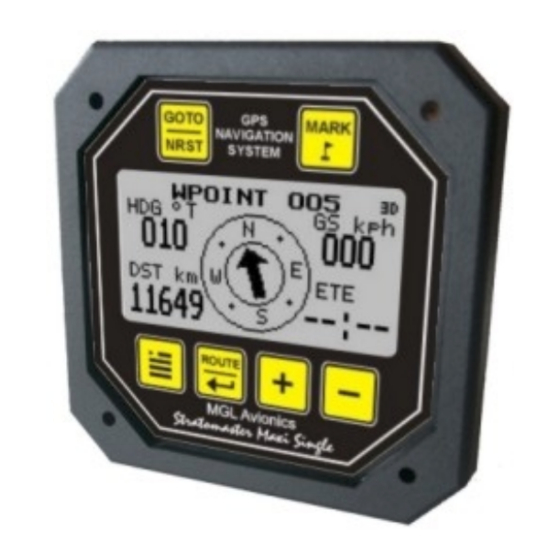
Description of items: North Indicator: This is the direction of true north. Horizon, 45 Degrees above horizon and directly overhead: These 3 rings show the elevation of the satellite from the horizon (outer ring). Horizontal Accuracy (HACC): This is a value expressed in meters (m) indicating what the horizontal accuracy is of the position fix. - Page 6 Primary Navigation Screen This screen is your primary navigation screen when a route or waypoint has been selected. Information such as waypoint name, current heading, ground speed, distance to waypoint, ETE (Estimate Time Enroute), as well as an arrow indicating the direction to your desired destination is displayed.
-
Page 7: The Menu System
The Menu System Waypoint Setup This menu allows the user to create and manage their waypoint database. Note: The GPS-1 can store up to 150 waypoints. New Waypoint The user can create a new waypoint by entering a unique identifier up to 10 characters long. By default the latitude and longitude is the current position. - Page 8 View Waypoint Select “View Waypoint” to view a waypoint. Use the keys to highlight the waypoint that you want to view. Press to view it. The distance and track is referenced to the current position. Edit Waypoint Select “Edit Waypoint” to edit a waypoint. Use the keys to highlight the waypoint that you want to edit.
-
Page 9: Marking A Waypoint
Waypoint Alert The GPS-1 will notify the user when he is approaching the selected waypoint. Use the keys to adjust the distance to the waypoint when the message alert must appear. Marking a Waypoint Use the key during the normal operation to mark a waypoint. -
Page 10: Route Setup
Waypoint Messages This message box will appear when an operation on a waypoint is performed and there are no waypoints stored in the waypoint memory. Route Setup New Route The user can create a new route by entering a unique identifier up to 10 characters long. - Page 11 Remove Waypoint Select “Remove Waypoint” to remove a waypoint from a route. Select the route the waypoint is in. Use the keys to highlight which waypoint is to be deleted. Press to delete the waypoint from the route. View Route Select “View Route”...
-
Page 12: Starting A Route
Edit Route Name Select “Edit Route Name” to change the route name. Use the keys to select the route name to edit. Press to select. Once finished editing the route name, move the highlight over ***save*** and press Delete Route Select “Delete Route”... - Page 13 The route selected message box will appear. Route Messages This message box will appear when an operation on a route is performed and there are no routes defined in the route memory. Sunrise/Sunset Calculator This sunrise/sunset calculator uses a unique algorithm based on date and position to accurately determine the sunrise and sunset times.
-
Page 14: Setup Menu
Setup Menu Select this menu to change various options such as North Reference, Magnetic Variation, position format, Distance/Altitude units, UTC (Universal Time Coordinate) offset and CDI (Course Deviation Indicator) Scaling . North Reference This option allows the user to change all Bearing/Heading related data to reference either to True or Magnetic North. - Page 15 UTC (Universal Time Coordinate) Offset This option allows the user to change the UTC offset. Use the keys to increment and decrement the time in 10 minute steps. CDI (Course Deviation Indicator) Scale Use this function to adjust the CDI scale to either 1, 2 or 5. Use the key to toggle this option.
-
Page 16: Nmea Output
The GPS-1 supports active antennas only. An active antenna contains the radiating element as well as a LNA (Low noise amplifier). Additional active antennas can be purchased from MGL Avionics if your antenna is rendered faulty. The GPS antenna is terminated in an mmcx connector. -
Page 17: Antenna Placement
Open Circuit Message The message will disappear as soon as an antenna is attached to the unit. Initialising Antenna Message The GPS-1 is busy initializing the antenna. This message will disappear as soon as this initialization has been completed. Antenna Problem Please check the antenna and rear antenna connector for possible damage. -
Page 18: Technical Specifications
Tracker only uses 6 characters for the waypoint name. When uploading these points to a PC any waypoint names that are longer then 6 characters will be truncated. Please be aware that various GPS applications have slight differences when managing waypoints and routes. It is recommended that the user has fully tested these programs before navigating with the GPS- Pinout DB9 Pin 2 ->... -
Page 19: Warranty
Warranty: MGL Avionics warrants their products for a period of one year from date of purchase against faulty workmanship. Warranty is limited to the replacement of faulty components and includes the cost of labor. Shipping costs are for the account of the purchaser.
Need help?
Do you have a question about the Stratomaster Maxi Singles GPS-1 and is the answer not in the manual?
Questions and answers