
Related Manuals for MGL Avionics IEFIS MX1


Summary of Contents for MGL Avionics IEFIS MX1
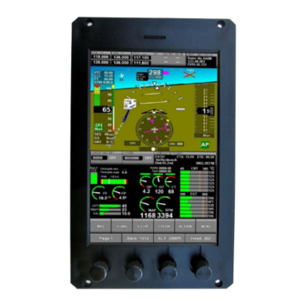
- Page 1 IEFIS MX1 Installation Manual Preliminary document Document date: 24 July 2019 Page 1...
-
Page 2: Table Of Contents
Table of Contents General............................5 The rear panel..........................7 Example system design......................8 IEFIS MX1 Panel terms.......................9 Master panel...........................9 Secondary panel........................9 Assigning iEFIS panel addresses....................9 Configuration of the iEFIS system....................10 Navigating the menus.......................10 Configuring a system for the first time..................10 System backup – cloning the internal disk................11 The “system setup”... - Page 3 Upload firmware to MGL Device...................19 System Basic setup functions....................19 Engine monitoring setup......................21 RPM 1 and RPM 2 setup menu....................22 Engine HP calculation setup....................22 TC Channel scan setup......................23 Using universal TC channels:...................25 EGT setup menu........................26 CHT setup menu........................26 Oil temperature setup menu....................26 Oil pressure setup menu.......................27 Coolant temperature setup menu..................27 AUX1 temperature setup menu....................28...
- Page 4 ALT Sensor gain........................53 Zero ASI and AOA sensors....................53 ASI calibration........................53 VSI Calibration factor......................54 Ambient temp calibration......................54 Internal IMU setup.........................54 Reset Gyro Bias........................54 Level the accelerometer.......................54 Gyro coupling coefficient.......................55 Load Extender firmware from SD card..................56 Serial port routing/Allocations....................57 Flight data recording setup.......................58 Setup GPS and NMEA port operation..................59 Selecting the GPS source.....................59 NMEA GPS at........................59...
-
Page 5: General
General The IEFIS MX1 consists of one or more panels and optional interface and sensor devices as may be required by the application. The iEFIS MX1 panel itself provides the following: Portrait mode sunlight readable color display with projected capacitive touch panel. - Page 6 MGL Autopilot servos (Bank, Pitch, Yaw) MGL/Trig TT21 and TT22 mode-s transponder Sandia STX165 remote transponder Remote transponders via MGL CAN bus interface (check for availability with MGL) Remote COM radios via MGL CAN bus interface (check for availability with MGL) MGL iEFIS Extender provides additional 5 RS232 ports, 8 Analog/Digital inputs, 4 user assignable outputs and 1 alarm output.
-
Page 7: The Rear Panel
The rear panel This image shows the rear of the iEFIS MX1 panel. Ensure that ventilation holes on top and bottom are not blocked in your installation. These holes provide convection cooling for the internal electronics. The rear panel provides a single DB25 female connector providing power input, CAN bus and four RS232 ports, audio output, OAT sensor input and Keep Alive power input. -
Page 8: Example System Design
Example system design The above image shows a typical small tripple panel system. It serves well to illustrate the simplicity of the distributed system and ease of hardware installation. Most MGL devices are connected to the MX1 using the CAN interface. The CAN bus uses a simple two wire connection. -
Page 9: Iefis Mx1 Panel Terms
The MX1 is well suited to simple single panel systems without further devices connected right up to highly complex multi-panel systems. IEFIS MX1 Panel terms Master panel In the iEFIS system, one and only one panel is the “Master” panel. The master panel has special privileges such as being able to configure all of the system. -
Page 10: Configuration Of The Iefis System
the affected panels. Panel address is set in each panel using its "Operation setup menu". Configuration of the iEFIS system This section refers to the configuration of the software side of the system once the hardware has been installed. Here you will select the various operating modes and settings and tell the iEFIS system what is connected and where it is connected. -
Page 11: System Backup - Cloning The Internal Disk
Please refer to the iEFIS alteration guide document for guidance on how to design your own screens. Once your screen layout selection has been completed, it is time to configure the individual settings. Here we start by setting the “real time clock” to the current time, setting up the “hobbs”, “maintenance”... -
Page 12: The "System Setup" Menu
The “system setup” menu Menu -> System setup This is the central place in your iEFIS system where you control how the system operates. This is the largest menu in the system. Note: All setup functions are available in the “Master” panel. All other panels may have certain functions suppressed as they are not permitted to be executed in such a panel. -
Page 13: Broadcast/Accept Functions And Setup
Broadcast/Accept functions and setup Here you select if a panel may accept certain data from other panels. You can select to allow setups to be accepted and what type of setups may be accepted. You can also choose if a panel may accept navigation from other panels. Depending on your requirements you may want to keep a panels navigation private to that panel. -
Page 14: Engine Monitoring Setup
Engine monitoring setup This large setup item has a chapter of its own and is not described here. Fuel related setup In the fuel related setup menus you will find setting for physical fuel tanks (based on level senders), virtual fuel tanks (based on fuel flow), Fuel flow setup and Fuel pressure measurement setup. -
Page 15: Setup Horizon Sensor
Here you will find many setups directly related to navigation. If you have multiple navigation databases installed, you can select the currently active database here. Also view the separate document “MGL Avionics map and database installation”. Setup GPS and NMEA port operation Select GPS source used for position, heading and track if you have multiple sources. -
Page 16: Ils/Gls/Gvor Setup
Please refer to the autopilot document for details on the autopilot setup. Differences to the document: iEFIS supports only MGL Avionics servos on CAN bus. For this reason selection of other servo types is not available. Autopilot servo tests and checks This functions is used to engage and position servos for purposes of installation and maintenance. -
Page 17: Serial Port Routing And Allocations
Serial port routing and allocations Select what you have connected to the various serial RS232 ports available. Note ports 1 to 4 are internal ports. These are mandatory for use for certain data connections such as GDL-90 ADSB. Should you have an iEFIS Extender connected you must use port 4 for the extender. In this case your internal ports are 1 to 3 and ports on the extender are 4 to 8. -
Page 18: Flap, Pitch And Roll Trim Indicator And Control Setup
120.025 is 120.025 Mhz with 25Khz bandwidth requirements 120.030 is 120.025 Mhz with 8.33Khz bandwidth requirements 120.035 is 120.0333 Mhz 120.040 is 120.0416 Mhz 120.050 is 120.050 Mhz with 25Khz bandwidth requirements 120.055 is 120.050 Mhz with 8.33Khz bandwidth requirements 120.060 is 120.0583 Mhz 120.065... -
Page 19: Standard System Selections
Should no suitable built in screen selection be available, you can create a custom design using the MGL Avionics Screen designer and simulator application. You can base your design on existing screens or you can start from scratch, providing every detail of your own screen design. - Page 20 Do not use the file manager to replace the internal setup.dat file. Tip: You can broadcast your setup when you are done to other panels via the CAN bus. This takes only an instant and does not alter any panels private settings. You can setup on each panel if and what type of setups to accept from other panels.
-
Page 21: Engine Monitoring Setup
Engine monitoring setup The engine monitoring setup is available from the Setup menu. It is recommended that you perform Select how many RDAC units (up to 4) are connected to this system. Typically you would have one RDAC per engine but you can also use more than one RDAC for a single engine. Use of the various probes and senders would be determined by your screen design. -
Page 22: Rpm 1 And Rpm 2 Setup Menu
RPM 1 and RPM 2 setup menu The RDAC has two RPM inputs. You would typically use only one of them. If you are monitoring RPM via p-lead connection, the RPM will drop out when the magneto is shorted during the mag test. In this case you should connect both RPM 1 and RPM 2 to either magneto system so that one of the inputs always has an RPM signal. -
Page 23: Tc Channel Scan Setup
Typical engine HP calculation screen. Please consult documentation for suitable values for your aircraft. The above values are typical for a Lycoming O320. TC Channel scan setup Page 23... - Page 24 This setup is relevant for your EGT and CHT functionality. The RDAC has 12 thermocouple inputs. Here you select which channels are used for EGT, which channels are for EGT and you can also assign up to 4 unrelated TC channels for general purpose temperature monitoring functions.
-
Page 25: Using Universal Tc Channels
Using universal TC channels: You can assign up to 12 independent thermocouple channels for general temperature monitoring. Here we assigned TC11 and TC12 on the RDAC for channels 1 and 2. Probe types for universal TC use are assumed to be K types. Each probe has a separate setup menu. -
Page 26: Egt Setup Menu
EGT setup menu Setup temperature ranges for display and alarm enables as needed. Caution level is the threshold from green to yellow. Alarm level is the threshold from yellow to red. If the box next to the level is checked, alarm or caution function is enabled for that level threshold. -
Page 27: Oil Pressure Setup Menu
Please refer to the EGT setup menu for description on level setup. Select the desired probe type used for monitoring the oil temperature. Standard NTC is the most common type – this is a standard VDO sender. Oil pressure setup menu Similar to the oil temperature setup menu, please select the relevant oil pressure probe type and set the pressure range of the probe. -
Page 28: Aux1 Temperature Setup Menu
AUX1 temperature setup menu Please refer to Oil temperature setup menu. This is very similar. The AUX1 temperature channel is typically used as CHT 1 on a Rotax 912/914 installation which uses NTC probes to measure cylinder head temperatures. For a Rotax engine you would select the “Standard NTC” probe (Standard VDO). Please refer to the Rotax manuals for operational temperature limits. -
Page 29: Temp/Tc 1 To 12 Setup
Tip: The manifold pressure system can also be used to measure other pressures. In this case you may want a custom screen design so indication shows the medium measured. The probe can be used for any non-aggressive medium. Fuel vapor is not a problem but do not expose to liquid fuel containing alcohol as this may damage the sensor flourosilicon encapsulation in the long term. -
Page 30: Current Sensor Setup Menu
Current sensor setup menu You can connect a current sensor to the RDAC XF current monitoring input. This input expects a system that will settle at approximately 2.5V if no current is detected. Any current flowing will increase or decrease this voltage depending on the direction of the current (for example battery charge/discharge). -
Page 31: Fuel Related Setup
Fuel related setup Fuel range/endurance setup Here you select which of your fuel quantity measurement sources contribute to the aircraft's range. For example, you may have a physical tank but also a virtual tank. The virtual tank is based on fuel flow and a entered starting value. Is the virtual tank a separate tank or is it a backup indication of the physical tank ? Fuel level sender damping This system wide setting affects how rapidly your physical fuel level sender readings will react... -
Page 32: Setup Rdac 1,2,3,4 Fuel Probes And Senders
Setup RDAC 1,2,3,4 fuel probes and senders The RDAC XF has two fuel flow sender inputs. You can use them as two separate fuel flows (and associated virtual tanks) or as a single, differential flow system where (Total flow = Flow 1 –... -
Page 33: Fuel Flow 1,2 Setup Menu
Fuel flow 1,2 setup menu Select the type of flow sender. Turbine refers to a typical flow sender that has a built in impeller that rotates with flow. You can also connect either high or low side firing electric fuel injectors. The K-factor refers to the number of pulses for 1 liter of flow. -
Page 34: Fuel Tank Setup Menu
and display are stored in the panel. Broadcast any changes here to other panels. Fuel tank setup menu This menu provides the functions needed to set up your physical and virtual fuel tanks. Here you set your virtual tank sizes and alarm levels and enables. You set your physical tank sizes and alarm levels and enables. - Page 35 A tank calibration consists of a six point calibration table. Perform the calibration AFTER you have set the correct tank size. Fill the tank starting from empty or reserve level and take note of the raw tank level reading shown in the top line. This reading is the actual raw ADC reading from your RDAC. Make a note of every tank reading at the various calibration points as you fill your tank with a measuring device (for example a calibrated container).
-
Page 36: Flight Instruments Setup
Flight instruments setup Here you setup details of ASI, VSI, AOA and GForce indicators Airspeed indicator setup Enter speed range for the round analog airspeed indicator (can be used in custom screen designes). ASI resolution for your airspeed indicator tape – set this according to the speed Page 36... -
Page 37: Vsi Type And Compensation Factor
range of your aircraft. The default setting of 10 km/h/mph/knots per 25 vertical pixels is usually sufficient for most applications. If you have the ambient temperature sensor (OAT) connected to your iBOX and accuractely calibrated, you should select “Use ambient temp sensor for TAS”. This tends to provide a more accurate result for TAS calculations compared to use of the “standard atmospheric model”... -
Page 38: Differential (2 Port)
Differential (2 port) This method uses two ports, a positive and a negative pressure port. Pressures are normally measured at the wing leading edge, a small hole above and a small hole below the cord line. The best positions should be obtained from the aircraft manufacturer. Do not place these holes too close to the leading edge. -
Page 39: Set Aoa Cruise Now
Set AOA cruise NOW... This menu item will only show if you have a single port AOA sensor selected (relative sensor mode, setup in “Instruments setup”). The single port sensor measures a pressure relative to static pressure and needs to have a “zero”... -
Page 40: Gforce Level Setup Menu
area. With a single port probe the indicator will be towards the lower end of the green area during normal cruise. Your aircraft should enter the stalling regime when the indicator crosses into the yellow area. In landing configuration with full flaps your aircraft should stall when crossing from yellow to red. -
Page 41: Analog/Digital Inputs Setup
Analog/Digital inputs setup The Extender, if you have one connected provides 8 user inputs. Each input can be used in analog or digital fashion. A digital input is on or off. The analog input returns a an analog value of between 0 and 4095 for a voltage applied from 0 to 16V. The usage of each inputs depends on your application. -
Page 42: Setting Up The Analog Channels
Setting up the analog channels Give the input a descriptive name. You may set levels for analog displays on the screen (for example a bargraph). You can observe the current raw value reading from the iBOX. ADC values range from 0 to 4095. -
Page 43: Setting Up Digital Channels
Setting up digital channels Give the input a descriptive name. Set the input to be active if level is high (>1.6V) or low (<=1.6V). The current active state is shown. Enable the alarm on active level if desired. Please note: Digital alarms are available on inputs 5-8 only. - Page 44 Up to three flap position warnings may be enabled based on flap position and airspeed. Flap position 3 is “full flaps” and would have the lowest maximum speed. Flap positions are obtained from the source selected in the “Flap indicator and control” setup and may be obtained from any analog input, Vertical Power VPX and the MGL Flap/Trim controller module.
-
Page 45: Flap Indicator And Control Setup
4 flap positions. These settings will be used to range the flap position indicator on the screen and show the intermediate positions.If you have a MGL Avionics Flap/Trim control module connected to the CAN bus, you will connect the flap position sensor to the control modules position sensing port. - Page 46 Page 46...
- Page 47 Page 47...
-
Page 48: Pitch Trim Indicator And Control
Controlling the flaps during flight is done by tapping the flap position indicator on the screen. This brings up a pop-up that allows you to set the flap position. Pitch trim indicator and control Page 48... - Page 49 3 trim positions. These settings will be used to range the pitch trim position indicator on the screen. If you have a MGL Avionics Flap/Trim control module connected to the CAN bus, you will connect the pitch trim position sensor to the control modules position sensing port. You can view the measured position value at the “Reading”...
-
Page 50: Roll Trim Indicator And Control
into the relevant slot position. Controlling the pitch trim during flight is done by tapping the pitch trim position indicator on the screen. This brings up a pop-up that allows you to set the trim position. Roll trim indicator and control For a passive indicator (no control) select one of the available analog inputs. - Page 51 3 trim positions. These settings will be used to range the roll trim position indicator on the screen. If you have a MGL Avionics Flap/Trim control module connected to the CAN bus, you will connect the roll trim position sensor to the control modules position sensing port. You can view the measured position value at the “Reading”...
-
Page 52: Internal Sensor Setup
Internal sensor setup This menu deals directly with setups stored in the IBOX. Several of the functions have to be performed during first system installation as described here. Altimeter offset calibration The altimeter calibration factor adds or subtracts about 7ft for every count at sea level. Page 52... -
Page 53: Alt Sensor Gain
This calibrates the offset of the altimeter. It is usually performed at close to sea level if possible or at your home airfield base. When you perform this calibration the MX1 also takes note of the ambient pressure you are performing the calibration at. This is used for the altimeter gain calibration. -
Page 54: Vsi Calibration Factor
VSI Calibration factor This calibrates the VSI indicator. A nominal 100% factor results in a very accurate VSI readout. It is not usually required to calibrate this readout. It is included here for completeness rather than necessity. Ambient temp calibration This adds or subtracts in one degree steps to your ambient temperature sensors current reading. -
Page 55: Gyro Coupling Coefficient
down) to 1G. Note that this function is different to the similar function in the AHRS setup menu (also under system setup). The functions in the AHRS setup menu are used to cancel small installation errors or allow a larger pitch tilt to be set for installation. These functions do not affect sensor calibration at all. The accelerometer level function here MUST be performed with the EFIS perfectly level, i.e. -
Page 56: Load Extender Firmware From Sd Card
External AHRS is connected onto the CAN bus. Load Extender firmware from SD card From time to time new firmware for the iEFIS Extender may be released by MGL Avionics. This firmware may be obtained by a free download from the MGL Avionics website. -
Page 57: Serial Port Routing/Allocations
Serial port routing/Allocations The MX1 provides 4 serial RS232 ports. If you are using an iEFIS Extender this is connected to RS232 port 4 and the Extender itself has 5 RS232 ports leaving you with a total usable number of ports of 8. To enable the Extender you select it in the Equipment enables setup menu. -
Page 58: Flight Data Recording Setup
“MGL blackbox data feed”. If the serial port is configured, recording data transmission is active when a flight is active. It cannot be disabled. Data format of the recording is placed in public domain. You can use the MGL Avionics iEFIS black box data viewer to view recordings. -
Page 59: Setup Gps And Nmea Port Operation
“iEFISBB.DAT”. It has the same file format as the conventional SD card recording and is about 2 MB in size. Setup GPS and NMEA port operation Selecting the GPS source You can select from three GPS sources: a) Internal GPS refers to the GPS engine in the MX1. This source is qualified to SIL/SDA of 1/1 according to the requirements of TSO-C199 and is RAIM capable. -
Page 60: Nmea Port Output Messages
NMEA port output messages The NMEA port on the iBOX outputs the following messages: GPGBS, GPGGA , GPGSV, GPGSA, GPGLL, GPRMB, GPRMC Sync RTC to GPS time Tick this box if you would like your internal real time clock to be synchronized to GPS time. Your UTC offset entered into the “Common Tasks menu”... -
Page 61: Gps And Ads-B
GPS and ADS-B Please refer to the separate document “iEFIS GPS.pdf” from the MGL Website with more in- depth information about the GPS system. Please refer to the separate document “ModeS-ADSB.pdf” from the MGL Website for detail information on how to use the SP-12 GPS module with an iEFIS and a compatible mode-s transponder for ADS-B compliance. -
Page 62: A Brief Description Of The Screen System
For information on how to create your own screens or modify existing screens please read the “iEFIS alteration guide.pdf” document available from the MGL Avionics website. There is also another useful document called “MGL iEFIS Rotor craft setup.pdf”. Even if you do not have a rotor craft –... -
Page 63: Upload Firmware To Mgl Device
EFIS update program cannot find the device it may be that your device is an older version that does not have the ability to be updated via the EFIS. In this case you may have to consider having it updated by MGL Avionics or one of its technical support locations should this be required. -
Page 64: Rear Panel Connections
Rear panel connections GPS Antenna A standard SMA female connection is provided for the GPS antenna. The antenna type required is an active GPS antenna powered by a DC voltage of 3V-3.6V. Please mount the antenna in the correct orientation facing the sky in an area where visibility is not restricted by Page 64... -
Page 65: Db25 Connector
any conductive surfaces or materials that attenuate RF signals. The antenna should also be installed as far from any potential interference sources as possible. Do not shorten or lengthen antenna cables as the amplifiers in the antenna are designed to compensate for the length of the antenna cable. -
Page 66: Unmarked Pins
Pin 23 Pin 24 CAN-H Pin 25 Unmarked pins All unmarked pins may be used as convenient signal ground points or for other uses. Please note that these pins are NOT INTERNALLY CONNECTED. Any signal grounds, where required should be connected to pins 3 and/or 4 (Power supply ground). This way no damaging ground currents can flow through the EFIS in case of an external ground fault. -
Page 67: Can Bus
Voice sounds originate from the file “Sounds.esd” that is preinstalled on your MX1 internal disks root folder. You can create your own sounds file using the Enigma Voice application available for download from the MGL Avionics website. It converts standard audio WAV files into the Sounds.esd file. -
Page 68: Low Speed Asi Ports
divider to lower the level. It may also be a good idea to route the audio via a toggle switch on your panel so you can easily mute the sound if desired. Audio signals may be noisy on certain installations – this tends to be caused by slightly different grounds between devices –... -
Page 69: Appendix
pneumatic T-connector. Should you have a low speed aircraft without a static port you will simply vent all your static ports into the cockpit (i.e. leave them unconnected). Differential AOA pickups consist of a small hole near the wing leading edge on top of the wing and one similar hole at the bottom of the wing. - Page 70 0,0,0,0,0 ;0 0,0,0,0,0 ;0.5 0,0,0,0,0 ;1 0,0,0,0,0 ;1.5 0,0,0,0,0 ;2 0,0,0,0,0 ;2.5 0,0,0,0,0 ;3 0,0,0,0,0 ;3.5 0,0,0,0,0 ;4 0,0,0,0,0 ;4.5 0,0,0,0,0 ;5 0,0,0,0,0 ;5.5 400,1000,0,0,3 ;6 400,1000,0,0,3 ;6.5 400,1000,0,0,3 ;7 400,1000,0,0,3 ;7.5 600,1000,0,0,2 ;8 600,1000,0,0,2 ;8.5 1000,1000,0,0,2 1000,1000,0,0,2 ;9.5 1500,1000,0,0,1 1600,1000,0,0,1 ;10.5 1700,1000,0,0,1;11...
-
Page 71: Can Bus Primer
1800,100,100,10,1 ;16.5 1800,100,100,10,1 1800,100,100,10,1 ;17.5 1800,100,100,10,1 1800,100,100,10,1 ;18.5 CAN bus primer The CAN bus (Controller Area Networking) was defined in the late 1980 by Bosch, initially for use in automotive applications. It has been found to be very useful in a wide variety distributed industrial systems and is becoming popular in avionics applications due its robustness and ease of use. -
Page 72: Making Twisted Wire
of currents flowing via the shield which can lead to interference (ground loop effects). Making twisted wire It is very easy to make your own twisted wire. Simply take two equally long wires (for example 5 meters) in parallel and tie one end (both wires) to a fixture (a door handle works well). Insert the other end (both wires) into a drill.
Need help?
Do you have a question about the IEFIS MX1 and is the answer not in the manual?
Questions and answers