Table of Contents
Advertisement
Quick Links
Advertisement
Table of Contents

Related Manuals for Zetor PROXIMA HS 100 2022


Summary of Contents for Zetor PROXIMA HS 100 2022
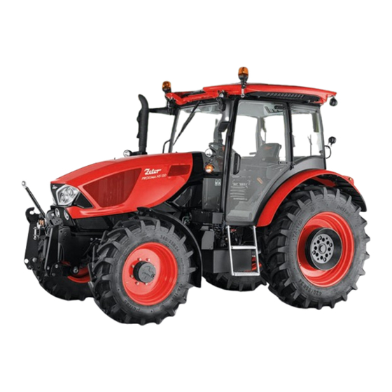
- Page 1 PROXIMA HS OPERATOR´S MANUAL 01/2022 Tractor is Zetor. Since 1946.
- Page 2 ZETOR This Operator’s Manual for the Zetor tractors, which we are presenting to you will help you to become familiar with the operation and maintenance of your new tractor. Although many of you have rich experience with the operation of other tractors, please, read the information contained in this Operator’s Manual very carefully.
-
Page 4: Table Of Contents
Aggregation tractor - machine/trailer ......................25 Tractors equipped with front end loader ...................... 25 Principles for operating tractors equipped with front end loader ..............26 Zetor tractors used for work in the woods ....................27 Safety labels ..............................27 Preventive daily service ..........................29 Preventive daily maintenance........................ - Page 5 CONTENTS Fast cooling of the space of the cabin ......................43 Immediately after cooling the cabin ......................44 Operation of heating or air-condition with tractor´s work ................44 Heating and air conditioning vents ......................45 Heating and air conditioning vents control ....................45 Control panel on right cab pillar ........................
- Page 6 CONTENTS Instrument panel - warning .......................... 74 Replenish fuel .............................. 74 Add urea ..............................75 High temperature of the cooling liquid ......................75 High oil temperature in the gearbox ......................76 Full pushing filter of the gearbox distributor ....................76 Full pushing filter of the hydraulics ......................
- Page 7 CONTENTS Blocking and automatic gear change of multiplier ..................102 Travelling up the slope ..........................102 Travelling down the slope .......................... 102 Differential lock ............................103 Control of front driving axle ........................103 Driving with engaged front driving axle ..................... 104 Manual brake - signalization ........................
- Page 8 CONTENTS Switching on the rear PTO shaft - dependent revolutions ................. 128 Front PTO shaft ............................129 Activation of the front PTO shaft - common working mode ............... 129 Activation of the front PTO shaft - stationary working mode ..............130 Deactivation of the front PTO shaft ......................
- Page 9 Oil for the front driving axle ........................186 Liquid for the cooling system of the tractors ....................186 Fuel for Zetor engines which are equipped with diesel paricle filter ............186 Urea (urea solution AUS 32) ........................186 Safety instructions for lubrication of the tractor ..................187 Tractor greasing plan ..........................
- Page 10 CONTENTS Hitch mouth for a trailer ..........................188 Upper linkage bracket ..........................188 Technical maintenance of the tractors after a general overhaul of the main groups ....... 188 Maintenance instructions ..........................189 Maintenance - LUBRICATION SYSTEM ....................189 Checking oil levels in engine ........................189 Draining oil from engine ..........................
- Page 11 CONTENTS Adjustment of hitch for single-axle trailers ....................208 Adjustment of bowden cable ........................209 Main technical parameters .......................... 211 Main tractor's parameters (mm) ........................ 211 Technical data of engines .......................... 212 Permitted maximum load of front axle (kg) ....................213 Permitted maximum load of rear axle (kg) ....................
-
Page 12: Location Of Serial Numbers
LOCATION OF SERIAL NUMBERS PCLS5N004.gif 1. Tractor data plate 2. Cab serial number 3. Engine serial number 4. Tractor serial number When ordering spare parts and within all written and oral communication always specify the data of your tractor that should be written in the frames below. Tractor type Tractor serial number Engine serial number... - Page 13 LOCATION OF SERIAL NUMBERS The 'right', 'left', 'front' and 'back' indications refer to the driving direction of the tractor. PCLS5N005...
-
Page 14: Safety Instructions For Users
SAFETY INSTRUCTIONS FOR USERS Pay increased attention to the parts in the instructions for use and maintenance indicated with this symbol. The symbol can be found next to all important warnings related to the operational safety. Follow these warnings and be particularly careful in these situations! Inform your colleagues and other users about these warnings. -
Page 15: Used Pictograms
SAFETY INSTRUCTIONS FOR USERS Used pictograms Engine oil pressure Differential lock Engine failure Slow operation Engine coolant temperature Fast operation Engine air filter clogged Hydraulic oil filter Engine emissions system, failure or Force regulation malfunction Engine emissions system temperature, Position regulation regeneration underway DPF filter clogged Upper working position... - Page 16 SAFETY INSTRUCTIONS FOR USERS Read operator's manual Rear work light Service indicator Work light Information alert Bonnet, front working lights Operator alert Tractor, auxiliary headlights Engine, urgent stop Beacon Engine glow plugs Interior compartment illumination Battery charging condition Rear fog lights Fuel Windscreen wiper, intermittent Hourmeter...
- Page 17 SAFETY INSTRUCTIONS FOR USERS Seat occupant switch Seat adjustment, longitudinal (fore and aft) Seat adjustment, seatback recline Bottom seat cushion-Longitudinal adjustment controller Seat turning controller Seat tilt controller...
-
Page 18: General Safety Regulations
SAFETY INSTRUCTIONS FOR USERS General safety regulations • The tractor may only be operated by a trained person that has a valid driving licence and has been thoroughly acquainted with the operation and safety rules. • Besides the safety instructions mentioned in the Operator´s Manual you are obliged to respect generally valid safety and traffic rules of the country where the tractor is used. -
Page 19: Driving Operation
• During aggregation of Zetor tractors with machines and implements with high tensile resistance when the engine speed drops and the engine tends to stall, the 1R, 2R reduced gears must not be used for... -
Page 20: Risk Of The Tractor Overturning
SAFETY INSTRUCTIONS FOR USERS Risk of the tractor overturning The risk of the tractor overturning is increased especially when the following is used: • a narrow wheel gauge • inappropriate tractor travelling speed • travel on the slope along a contour line or turning on the slope •... -
Page 21: Leaving The Tractor
SAFETY INSTRUCTIONS FOR USERS Leaving the tractor • Park the tractor only on an even land and where not possible, support with a shim assy. • Do not park the tractor with an attached implement in the lifted position. • Usually use the left-hand side tractor door when leaving the tractor. Look round whether any vehicle is coming, that could jeopardize your safety when leaving the tractor. -
Page 22: Preventive Daily Maintenance
SAFETY INSTRUCTIONS FOR USERS Health and environment protection • The tractors are not equipped with special filters of air aspirated to the cab. Therefore, they are not designed for work with aerosols and other harmful substances. • Coolant, brake liquid, kerosene, diesel fuel, mineral oil and other oil products that are used for the operation and maintenance of the tractor may cause various skin disorders in case of direct contact with your skin and can irritate mucous membranes, eyes, the digestive system and upper respiratory ways. - Page 23 • When handling the battery you must pay increased attention and avoid short-circuits. In tractors equipped with a battery disconnector switch the disconnector off when handling the battery. • Zetor tractors must not be operated with a disconnected battery as this may lead to a serious failure of the tractor.
-
Page 24: Driver's Seat
PCLP18N003 is operated. Protection of cab against aerosols The cab of Zetor tractors in standard version is not designed for work with aerosols and other harmful substances. The level of protection of the cab in the standard version is in accordance with standard EN 15 695-1:2017, category 2 (dustproof cab only). -
Page 25: Level Of External And Internal Noise
82,1 The level of vibrations on driver´s seat ZETOR tractors are classified in the category A and the class I/II/III. The category A includes all tractors with specified levels of vibration due to similar specifications of the construction. The following table presents the results of the measurement on the test bench according to the Commission Delegated Regulation (EU) No. -
Page 26: Aggregation Tractor - Machine/Trailer
Tractors equipped with front end loader Zetor Tractors in standard design are designed for utilization in agriculture and are not designed for special purposes. Tractors designed for operation within the European Union must be equipped, in case of using front end loader, with a protective structure (FOPS - Falling Object Protective Structure) protecting drivers from potential falling objects. -
Page 27: Principles For Operating Tractors Equipped With Front End Loader
ZETOR´s ap-proval. The loader may become dangerous as a result of not observing these instructions. ZETOR TRACTORS shall not be held responsible in case of any damage or injury. • Use front end loader without additional weights on the tractor (danger of mutual contact). The load of front and rear drive axle must not exceed the maximum permitted load listed in the manual. -
Page 28: Zetor Tractors Used For Work In The Woods
Standard tractors Zetor do not provide sufficient protection for operation in forest terrain as, for example, protection against a fal-ling tree or branch on a cab or penetration of objects to a cab. If Zetor tractor is utilized for forest work, a tractor operated within the European Union must be protected against these risks. - Page 29 NOTES ...
-
Page 30: Preventive Daily Service
PREVENTIVE DAILY SERVICE Preventive daily maintenance Perform this maintenance daily or after every 8 - 10 hours of operation at the latest. PCLS5N006.gif Fuel system leaks Check the fuel system, including the fuel tank, for leaks. Repair leaks immediately. The fuel tank drain bolt is at the bottom of the tank. -
Page 31: Windshield Washer Tank
PREVENTIVE DAILY SERVICE Windshield washer tank The windscreen wiper water tank is located on the outer rear wall of the cab. The capacity of the tank is 2 litres. During the summer, the tank must be filled with distilled water or with a summer windscreen wash mixture. In winter, it is necessary to fill it with an antifreeze solution for windscreen wipers. -
Page 32: Hydrostatic Steering
PREVENTIVE DAILY SERVICE Hydrostatic steering Oil for hydrostatic control is pumped from the gearbox cartridge • check the oil level in the gearbox • check the tightening of the nuts and bolts of the control rods and levers • check the condition of all the hoses of the hydraulic control circuit for damage and oil leakage PCLPNN072 Air cleaner... -
Page 33: Inspection Of Fouling Of Coolers
PREVENTIVE DAILY SERVICE Inspection of fouling of coolers Open the front cowl and check the plates of the engine radiator of engine cooling liquid and air conditioning condenser, the cooler of oil of the front PTO shaft and the cooler of the gear oil (if the tractor is equipped with them) for fouling. -
Page 34: Acquaintance With Tractor
ACQUAINTANCE WITH TRACTOR Tractor user must be properly acquainted with recommended operating and safety rules for safe tractor operation in advance. It is too late to do it within operation! Opening the bonnet To open the bonnet: Press the appropriate tool (e.g. screwdriver) against the rod (1) in the direction of the arrow to unlock the bonnet. -
Page 35: Opening The Door From The Inside
ACQUAINTANCE WITH TRACTOR Opening the door from the inside 1. Lever for opening the door from the inside 2. Lever for opening the door from the inside The door is held by a gas strut with a full opening. It is forbidden driving with open door due to its possible damage. -
Page 36: Sun Visor And Hinged Lid Cover
ACQUAINTANCE WITH TRACTOR Sun visor and hinged lid cover Pull out the sun visor of the windscreen (1), by pulling the handle in the direction of the arrow. To return to the starting position, briefly press the button (2). The sliding hinged lid cover (3) closes and opens by pushing or pulling the slots in the direction of the arrow. -
Page 37: Tools Box
ACQUAINTANCE WITH TRACTOR Tools box The tool box is located on the left side of the tractor from outside in front of the cab. PCLS5N089 On request, a fender box can be mounted on the tractor on the left side of the driver. PGPPN122 Right rear panel Tractor equipped with hydraulics with mechanical control... -
Page 38: Internal Lighting
ACQUAINTANCE WITH TRACTOR Internal lighting To be turned on and off by means of a button marked with the arrow. PGPPN179 Rear view mirrors Before the drive or starting the work, adjust rear view mirrors so that they enable to monitor the whole drive way or working field. -
Page 39: Passenger´s Seat
ACQUAINTANCE WITH TRACTOR Passenger´s seat Passenger´s seat is tiltable and placed on the left mudguard of the cabin. P15N028 Seat tilting out Passenger´s seat to be tilted out in the direction of an arrow (1) upward. Locking of the seat is done automatically. -
Page 40: Driver's Seat Sears
ACQUAINTANCE WITH TRACTOR Driver's seat Sears PGPPN124 The Sears driver's seat can be equipped with mechanical (A) or pneumatic (B) suspension. 1 - Seat suspension control according to the driver's weight (adjustment by rotation, direction according to the pictogram on the seat bellows) 2 - Seat height adjustment control (releasing the control - higher seat, tightening the control - lower seat) 3 - Lateral seat adjustment lever (after raising the lever, the seat can be adjusted laterally, the lever is locked by returning the lever to its original position) -
Page 41: Tilt Steering Wheel
ACQUAINTANCE WITH TRACTOR Tilt steering wheel Adjusting the angle of the wheel The angle can be adjusted by tilting the wheel after it is unlocked by moving the lever (1) in the direction shown by the arrow. After adjusting, lock the wheel by pressing the lever (1) in the opposite direction than shown by the arrow. -
Page 42: Heating Control Panel, * Air-Condition
ACQUAINTANCE WITH TRACTOR Heating control panel, * air-condition The heating and air conditioning control panel is located on the right side of the cab roof ceiling. A - heater valve control B - fan control C - air conditioning button D - cab air recirculation button PGPPN125 Heating valve control (A) -
Page 43: Cab Air Recirculation Control (D)
ACQUAINTANCE WITH TRACTOR Cab air recirculation control (D) Press button (D) to switch on and off the full internal air recirculation - Internal air recirculation switched off (indicated by the yellow control light), external air is sucked through the filters into the cab - Internal air recirculation switched on (indicated by the yellow control light), air is drawn from the cab and blown back into the cab, (internal air recirculation for quick... -
Page 44: Fast Heating Of The Cabin Area
ACQUAINTANCE WITH TRACTOR Fast heating of the cabin area PGPPN131 Proceed as follows: 1 - Turn the heating valve control (A) to the right (HI) position (fully open heating valve) 2 - Use the fan control (B) to select the appropriate fan speed (position 1, 2, 3) 3 - Switch on the internal air circulation with the switch (D) (the diode under the switch is on) 4 - Adjust the air vents at the desired angle so that the people in the cab are not directly blown on 5 - After heating the cab space, switch off the internal air circulation by pressing the switch (D) and set the... -
Page 45: Immediately After Cooling The Cabin
ACQUAINTANCE WITH TRACTOR Immediately after cooling the cabin PGPPN133 Immediately, after the cab has cooled down and the internal temperature has been lowered to the desired value, we recommend: 1 - Switch off the internal air circulation by pressing the button (D) 2 - By opening the heating valve (A), perform the continuous regulation of the air temperature, with the air conditioning on. -
Page 46: Heating And Air Conditioning Vents
ACQUAINTANCE WITH TRACTOR Heating and air conditioning vents PGPPN189 Heating and air conditioning vents, front (A), side (B). Heating and air conditioning vents control A - opening the vent - open the vent by pressing it, where indicated by the arrow B - closing the vent - close the vent by pressing the slat of the vent in the direction of the arrow C - change the direction of air flow from the vent - set the... -
Page 47: Control Panel On Right Cab Pillar
ACQUAINTANCE WITH TRACTOR Control panel on right cab pillar PGPS5N003 Layout of switches on standard version of tractor (A) 1 - Front wiper cycler switch 2 - two position front wiper switch and front washer control 3 - front wiper switch 4 - rear wiper switch 5 - rear-view mirror heater switch 6 - rear window heater switch... -
Page 48: Rear Window Wiper
ACQUAINTANCE WITH TRACTOR Rear window wiper The rear window wiper switch is located on the right pillar of the cab. The single-speed wiper of the rear window is controlled by a single-position switch. 0 - rear window wiper off 1 - rear window wiper on F18N012 Front and rear windscreen washer The button for controlling the front and rear windscreen... -
Page 49: Panel Of The Instrument Panel
ACQUAINTANCE WITH TRACTOR Panel of the instrument panel PHSS5N001 1 - Reverse lever (forward, neutral, reverse) 2 - Indicators, dipped and main beam switches, acoustic horn, beacon with horn 3 - Light switch (off, parking, main) 4 - Dipped-beam switch in the tractor bonnet and work light switch on the tractor cab 5 - Fog light switch (off-on). -
Page 50: Lights Switch
ACQUAINTANCE WITH TRACTOR Lights switch a - illumination off b - side and end point lights on, illumination of licence label, illuminated c - all devices on in 'b' position. Lower beam head lights or head beam lights are engaged (according to the position of direction lights, lights and horn switches). -
Page 51: Direction Lights, Lower Beam Head Lights, Head Lights And Horn Switches
ACQUAINTANCE WITH TRACTOR Direction lights, lower beam head lights, head lights and horn switches a - Acoustic horn - press the switch in the direction of an axis b - Low beam lights c - Direction lights to the right d - Direction lights to the left e - Acoustic horn f - High beam lights... -
Page 52: Switch Box
ACQUAINTANCE WITH TRACTOR Switch box Switchbox is placed on the dashboard, see arrow. PHSS5N005 Switch box key in the position (0) The voltage of all the equipment controlled via the key is disconnected. The key can be removed. PCLPN035 Switch box key in the position (I) The voltage is connected to all the equipment excluding starter. -
Page 53: Manual Throttle
ACQUAINTANCE WITH TRACTOR Manual throttle A - Maximum speed of the engine B - Idle run The lever allows setting of speed of the engine within range A to B. PHSS5N007 Pedals and levers 1. Travel clutch pedal 2. Foot operated service brake pedals connected by latch 3. -
Page 54: Gear Shifting Lever
ACQUAINTANCE WITH TRACTOR Gear shifting lever - main gear shifting lever 1. button for disengaging clutch on the head of gear shifting 2. buttons of shifting individual gears of multiplier PHS18N005 Gear shifting scheme Reverse speeds can be shifted with the reversing lever only. -
Page 55: Pto Selection Control Lever
ACQUAINTANCE WITH TRACTOR PTO selection control lever P18N016 a - independent revolutions of the PTO shaft drive - revolutions are dependent on the engine revolutions n - neutral position b - dependent revolutions of the PTO shaft drive through the gearbox - revolutions are dependent on the shifted gear Shifting is performed when the tractor is idling. -
Page 56: Battery Disconnector
ACQUAINTANCE WITH TRACTOR Battery disconnector P18N100 The battery disconnector is located on the left side of the tractor behind the driver's stairs. A - Battery connected B - Battery disconnected C - Disconnector plate is located on the cover of the accumulator battery When the engine is switched off, the engine control unit remains active for about 2 minute because of storage of operation data. -
Page 57: Fuel Tank
ACQUAINTANCE WITH TRACTOR Fuel tank The fuel tank is installed at the right-hand side of the tractor. The tractor is equipped with a plastic tank with the capacity of 190 litres. Do not step on the fuel tank! PCLS5N029 Fuel tank drain plug Plug for draining dirt and fuel off the fuel tank is in its bottom. -
Page 58: Instrument Panel
INSTRUMENT PANEL Instrument panel - signal lamps P18N039 1 - green - signal lamp of left direction lamps 2 - blue - distance lights signal lamp Lights up with distance lights on. 3 - green - signal lamp of direction lights of the 1st trailer 4 - green - signal lamp of direction lights of the 2nd trailer 5 - orange - warning signal lamp 6 - blue - operational protection signal lamp. -
Page 59: Instrument Panel - Instruments
INSTRUMENT PANEL Instrument panel - instruments P18N040 A - coolant thermometer B - fuel gauge C - engine speedometer D - information display Instrument panel - buttons P18N041 A - reset button, exit from menu of the instrument panel B - enter button, entry to menu of the instrument panel, item selection confirmation in the instrument panel menu C - button for rolling up in the instrument panel menu D - button for rolling down in the instrument panel menu... -
Page 60: Display Description
INSTRUMENT PANEL Display description PHSS5N028 The following values are displayed on the main display: 1 - reversing lever position 2 - shifted gear of multiplier of torque, according to shifted gear 1, 2 or 3 is displayed 3 - low air pressure indicator in the tractor's air pressure system 4 - graphical representation of air pressure in the air-pressure system of the tractor 5 - air pressure in the air-pressure system of the tractor 6 - viewing part of the display... - Page 61 INSTRUMENT PANEL When the key in the switch box is moved to position I, the home screen is displayed on the display. C15N030 After about three seconds the main screen is displayed on the display. 1 - total operating hours (the value cannot be reset) 2 - operating hours of the tractor since the last reset of the value 3 - total distance covered (the value cannot be reset)
- Page 62 INSTRUMENT PANEL There are data regarding automatic switching off of the rear PTO shaft; more information in the chapter Power of Agricultural Machines. PHS18N020 There are data regarding automatic shifting of the torque multiplier on this screen; more information is available in the chapter Driving.
-
Page 63: Display - Display Of Air Pressure In The Air-Pressure System Of The Tractor
INSTRUMENT PANEL Display - display of air pressure in the air-pressure system of the tractor P18N075 The air pressure in the tractor's air system is displayed on the instrument panel display. 1 - Air pressure symbol, white light, has no signaling function. 2 - Red display field, gradual filling of the field with red color indicates the increase of air pressure in the tractor's air-pressure system in the range from 0 bar to 4.5 bar. -
Page 64: Display - Resetting Data
INSTRUMENT PANEL Display - resetting data P18N047 The procedure for resetting data on the main screens where the data can be reset is as follows: 1 - Use the buttons (C) and (D) to select display of the corresponding main screen. 2 - Reset the data by longer pressing of the button (A) (RESET). -
Page 65: Display - Indicator Of Service Inspection Intervals
INSTRUMENT PANEL Display - indicator of service inspection intervals P18N070 The warning regarding an approaching maintenance date (service interval) is displayed if there are less than 25 operating hours remaining to the planned maintenance. The maintenance symbol (1) is shown on the display of the instrument panel. When the key in the switch box is moved from the position 0 to the position I, the main screen appears on the display and after several seconds the warning regarding an approaching maintenance (B) with the number of operating hours of the tractor (2) remaining to the maintenance date are displayed on the display. -
Page 66: Error Signalling
INSTRUMENT PANEL Error signalling Errors arising during tractor operation are indicated by switching the corresponding signal lamp, acoustic signal and error message in the instrument panel display. If the error is indicated, the signal lamp still glows, even though the display is switched to the next display. If the error is not eliminated or the indicated state has not returned to a normal state: the corresponding signal lamp glows... -
Page 67: Description Of The Display Of Error Messages
INSTRUMENT PANEL Description of the display of error messages 1 - The symbol of the defect significance. 2 - Node of the tractor where the defect appeared. 3 - Main display field - defect code. 4 - Secondary display field - defect specification. P18N074 Symbols of tractor nodes Engine... -
Page 68: Display - Setting Language Mutation
INSTRUMENT PANEL Display - setting language mutation P18N077 Press the button (B) to enter the service menu 1 - use the buttons (C) and (D) to select the item Language; press the button (B) to enter the screen with language mutations. 2 - use the buttons (C) and (D) to select the required language mutation and press the button (B) for confirmation. -
Page 69: Display - Setting Of Day And Night Backlight Of The Display
INSTRUMENT PANEL Display - setting of day and night backlight of the display P18N098 Enter the display settings menu. a - Use the buttons (C) and (D) to select the item for the day display backlight. Long press the button (B) to enter the screen for the display backlight setting (b). -
Page 70: Display - Setting The Automatic Mode Of The Display Backlight
INSTRUMENT PANEL Display - setting the automatic mode of the display backlight P18N099 Enter the display settings menu. a - Use the buttons (C) and (D) to select the item (1) for the automatic mode of the display backlight. Long press the button (B) to enter the screen for setting the automatic mode of the display backlight (b). -
Page 71: Display - Setting And Calibration
INSTRUMENT PANEL Display - setting and calibration PHS18N007 Press the button (B) to enter the service menu 1 - use the buttons (C) and (D) to select the item Calibration; press the button (B) to enter the screen with the calibration menu. 1 - setting of display of revolutions of the rear PTO shaft - more information in the chapter POWER OF AGRICULTURAL MACHINES 2 - calibration of travelling clutches... -
Page 72: Travel Speed Calibration
INSTRUMENT PANEL Travel speed calibration P18N096 The instrument panel after assembly in the factory is calibrated. Perform a new calibration of the travel speed: - after a considerable tyre wear - when installing new tyres - during replacement of the instrument panel Calibration procedure - indicate the track of the length of 100 m on a suitable place - inflate the tractor tyres to the specified pressure;... -
Page 73: Display - Machined Area
INSTRUMENT PANEL Display - machined area The processed area display shows the processed area in hectares. 1 - processed area in hectares 2 - processed area - average in hectares per hour 3 - fuel consumption - average in litres per hectare 4 - fuel consumption in litres from the start of the recording of the processed area. -
Page 74: Processed Area - User Selection
INSTRUMENT PANEL Processed area - user selection PSH18N010 Enter the processed area menu - user selection. Three aggregation widths can be adjusted for each user. There is an extra memory of the processed area for each user. In the use selection menu (a) use the buttons (C) and (D) of one out of three users. Shortly press the button (B) to select the user with the set aggregation. -
Page 75: Machined Area Record
INSTRUMENT PANEL Machined area record PHS18N012 Enter the aggregation setting menu. Check whether the proper user and aggregation width (1) are adjusted or perform setting of the user and aggregation width. Each user has their values of the processed area; when the user is changed, values valid for the selected user are displayed on the main screen. -
Page 76: Add Urea
INSTRUMENT PANEL Add urea The amount of urea in the tank is displayed on the instrument panel on the main screen. a - If the urea level is higher than 50%, it is displayed as OK on the instrument panel. If the amount is below 50%, the real amount of urea in percentage is displayed. -
Page 77: High Oil Temperature In The Gearbox
INSTRUMENT PANEL High oil temperature in the gearbox PHS18N042 High temperature of the gear oil is indicated in several stages of warning A - informative - reduce the engine power B - warning - stop the tractor, set the engine to idling until the temperature of the gear oil is reduced C - caution - stop the engine, wait until the temperature of the gear oil is reduced and check the level of the gear oil;... -
Page 78: Full Pushing Filter Of The Hydraulics
INSTRUMENT PANEL Full pushing filter of the hydraulics PHS18N045 The full oil filter of the hydraulics is indicated in several stages of warning A - informative - it will be necessary to perform replacement of the oil filter cartridge of the hydraulics (see chapter Maintenance Guidelines) B - warning - it is necessary to perform replacement of the oil filter cartridge of the hydraulics (see chapter Maintenance Guidelines) - Page 79 NOTES ...
-
Page 80: System Of Additional Treatment Of Exhaust Gases
SYSTEM OF ADDITIONAL TREATMENT OF EXHAUST GASES The tractor is equipped with an engine that meets the STAGE V emission limits. Compliance with the emission limit is achieved, among other things, through a combination of two exhaust gas after-treatment systems: a- Diesel particulate filter (DPF), which is used to retain particulates in the exhaust gases. -
Page 81: Dpf Filter Regeneration
SYSTEM OF ADDITIONAL TREATMENT OF EXHAUST GASES DPF filter regeneration By flashing the DPF orange light and turning on the orange warning light (A), the DPF signals the need to start the DPF filter regeneration. The operator must start the DPF filter regeneration in the instrument panel menu. Regeneration is carried out on a standing tractor with an idling engine that is braked by the handbrake (B), the reversing lever is moved to the neutral position (C) and the PTO clutch is off (D). -
Page 82: Conditions For Scr System Operation
SYSTEM OF ADDITIONAL TREATMENT OF EXHAUST GASES C18N036 8 - the regeneration of the DPF has begun, and the estimated time of the regeneration is displayed in the bottom line 9 - cooling the system after the regeneration is complete, DO NOT SWITCH OFF THE ENGINE! 10 - DPF filter regeneration is complete, you can continue to work with the tractor without restrictions Do not stop the engine during regeneration of DPF (the green signal lamp flashes) - there is a risk of damage of the system of treatment of exhaust gases. -
Page 83: Urea (Aqueous Urea Solution Aus 32, Def)
SYSTEM OF ADDITIONAL TREATMENT OF EXHAUST GASES Urea (Aqueous Urea Solution AUS 32, DEF) The used reagent is a mixture of 32.5% solution of synthetic urea and demineralized water. It is used as a reducing agent NOx for additional treatment of exhaust gases by SCR (selective catalytic reduction) of motor vehicles with diesel engines. -
Page 84: Error Signalling Of Scr System
SYSTEM OF ADDITIONAL TREATMENT OF EXHAUST GASES Error signalling of SCR system Defects of the SCR system when the engine is running are indicated by glowing of the red (1) or orange (2) signal lamp on the instrument panel and by the subsequent acoustic signal. -
Page 85: Indication Of Amount Of Urea In The Tank
SYSTEM OF ADDITIONAL TREATMENT OF EXHAUST GASES Indication of amount of urea in the tank P18N030 The amount of urea in the tank is displayed on the instrument panel on the main screen. a - If the urea level is higher than 50%, it is displayed as OK on the instrument panel. If the amount is below 50%, the real amount of urea in percentage is displayed. -
Page 86: Reduction Of The Engine Power And Engine Revolutions
SYSTEM OF ADDITIONAL TREATMENT OF EXHAUST GASES Reduction of the engine power and engine revolutions If a serious system fault occurs, the urea level in the tank is low or if the operating conditions are exceeded, the system reacts by reducing the engine power and speed. Depending on the type of error, the so-called one or two-level limitation of engine power will take place. - Page 87 NOTES...
-
Page 88: Operation
OPERATION Before a drive with the new tractor get to know how to shift gears and try individual positions of the shifting lever when the engine is stopped. During normal operation and before you set up, make sure that the technical condition ensures safe operation of the tractor. -
Page 89: Non-Permitted Starting
OPERATION Non-permitted starting It is prohibited to start the tractor by short-circuiting the terminals of the starter. Perform starting from the driver's seat only. During any handling or repair of the starter, the minus pole of the battery and all gear shift levers, including shifting of the PTO shaft, must be in the neutral position. -
Page 90: Starting The Engine While Using Coolant Heater
OPERATION Starting the engine while using coolant heater PCLS5N039 With low temperatures of the surroundings, engine starting eases heating coolant. Leadin electrical installation and its protection against dangerous contact must be done pursuant to valid regulations 1. First plug the plug to the heater. 2. -
Page 91: Error Signalling
OPERATION Error signalling Errors arising during tractor operation are indicated by switching the corresponding signal lamp, acoustic signal and error message in the instrument panel display. If the error is indicated, the signal lamp still glows, even though the display is switched to the next display. If the error is not eliminated or the indicated state has not returned to a normal state: the corresponding signal lamp glows... -
Page 92: Signalling Errors In The System Of Additional Treatment Of Exhaust Gases
OPERATION Signalling errors in the system of additional treatment of exhaust gases PHSS5N026 A plate with a brief description of fault indication of the exhaust gas after-treatment system and subsequent operator interventions is located in the lower right corner of the windscreen (A). On the plate (B), the pictograms on the left indicate the combination of the indicator lights switched on or flashing on the instrument panel, including their color, and the pictogram of the audible warning signal. -
Page 93: Diesel Particle Filter
OPERATION Diesel particle filter The exhaust system of a tractor is equipped with a diesel particle filter which serves for cleaning exhaust fumes. Solid particles (carbon particles) are collected and burned in diesel particle filter which originate by burning diesel. Filter of solid particles - indication of operation and failures of the system P18N058 The activity of a DPF filter is indicated by lights (1), (2) and (3) on the instrument panel. -
Page 94: Reversing Lever
OPERATION Reversing lever Use the reversing gear lever to select the tractor driving direction (forward or reverse). F - forward driving (24 speeds) N - neutral position R - reverse driving (24 speeds) There are 24 reverse speeds available at the reversing gearbox which are almost as quick as forward speeds. -
Page 95: Shifting Road And Reduced Speeds
OPERATION Shifting road and reduced speeds H - road speeds N - neutral L - reduced speeds Shifting of gears of the main gearbox with reduced speeds is the same as with road speeds. Considering low speed of the tractor, change nearly always means moving off from rest. -
Page 96: The Principles Of Appropriate Use Of Tractors
OPERATION The principles of appropriate use of tractors The listed principles for tractor´s operation serve for facilitating the operation and guarantee corresponding service life of travel clutch! The description of the system of travel clutches The tractor is equipped with two individual travel clutches, one for travelling forward and one for travelling backward. -
Page 97: Interrupted Sound Signal
OPERATION Interrupted sound signal PHS18N052 If the tractor speed is regulated by partial released clutch pedal at higher engine revolutions than 1,200 rpm, an interrupted audio signal is generated and a warning on the display of the instrument panel is shown. If this situation occurs, immediately fully pres the clutch pedal to the end or release the clutch pedal to its upper position and wait until the acoustic signal is deactivated. -
Page 98: Dead Start Of Tractor In Regular Operation - Automatic Dead Start Function
OPERATION Dead start of tractor in regular operation - automatic dead start function Automatic dead start function is in the shift of reversing lever with engaged applicable gear followed by dead start without using the clutch pedal or clutch control buttons. 1. -
Page 99: Change The Direction Of Drive
OPERATION Change the direction of drive Change the direction of drive by means of reversing lever Change the direction of drive by means of reversing lever is done with travel speed lower than 10km/h. When you attempt to change the direction of drive in speed higher than 10 km/h, acoustic signal starts (uninterrupted tone) and the tractor engages neutral. -
Page 100: Gear Shifting
OPERATION Gear shifting - For shifting the gear speeds while travelling use the travel clutch control by a red button of clutch control on the head of gear shifting lever. - When shifting gears, press and hold the red button of clutch control on the head of gear shifting lever, release the gas pedal, throw out the gear, shift an applicable gear speed, release the red button and then increase the engine revolutions. -
Page 101: Multiplier Preselection Switch
OPERATION Multiplier preselection switch PHSS5N011 The switch of the multiplier pre-selection is located on the board of the instrument panel. Activation of the switch is indicated with the activated symbol on the switch and the symbol in the instrument panel display. If the switch of the multiplier pre-selection is switched off, the gears of the multiplier can be shifted on the gear shift lever. - Page 102 OPERATION Display of values (engine revolutions) for automatic shifting of the multiplier The values (number of engine revolutions) stored by the system for automatic shifting of the multiplier when the buttons L and H are used are displayed on the corresponding main screen. More information in chapter INSTRUMENT PANEL.
-
Page 103: Blocking And Automatic Gear Change Of Multiplier
OPERATION Blocking and automatic gear change of multiplier If brake pedals are used with the controller of multiplier pre-selection on, the system of automatic gear change of multiplier blocks the automatic shift of multiplier to a higher gear (increasing taxing speed), automatic shift of multiplier to lower gear (lowering taxing speed) remains in operation. -
Page 104: Differential Lock
OPERATION Differential lock PHSS5N012 Switching on the differential lock is done by pressing the button on the dashboard, which returns to the original position when released. Switching on the differential lock is indicated by the illuminated symbol on the dashboard display, the indicator light on the dashboard and the illuminated symbol on the button. -
Page 105: Driving With Engaged Front Driving Axle
OPERATION Driving with engaged front driving axle Use the front drive axle when the rear wheels slip to increase traction. On roads and hard ground, driving with the front drive axle engaged is not recommended (driving with the front drive axle engaged causes increased wear on the front tyres). The front drive axle may be permanently engaged when front-mounted agricultural machinery or implements are attached to the tractor. -
Page 106: Foot Brakes
OPERATION Foot brakes Foot brakes are disc type, wet, controlled hydraulically by the pressure oil from common gearbox filling with strengthening effect of the pump and with automatic pressure equalization in brake circuits. When driving on the road, both pedals must be connected with a latch. -
Page 107: The Button For Temporary Deactivation Of Brakes Of The Trailer Or Semi-Trailer
OPERATION The button for temporary deactivation of brakes of the trailer or semi-trailer PHSS5N014 Prior to using the button for temporary deactivation of brakes of the trailer or semi-trailer, it is always necessary to provide sufficient space in front of the tractor and behind the connected trailer or semi-trailer where no obstacles or persons will be present for the case that the effect of the parking braking will not be sufficient and the combination of vehicles moves. -
Page 108: Air Brakes Of Trailers And Semi-Trailers
OPERATION Air brakes of trailers and semi-trailers PCLPN056 Air brakes of trailers (semi-trailers) and brakes of the tractor are designed so that braking effects of both vehicles are synchronised. In case of a drop of pressure the transfer valve disables the secondary consumers (differential lock, disengagement of the front driving axle). -
Page 109: Two-Hose Brakes
OPERATION Two-hose brakes The working pressure is set at 810 ± 20 kPa. The volume of the air tank is 20 l. The left head valve is marked in yellow (braking branch), the right head valve is marked in red (filling branch). When a trailer (semi-trailer) with a maximum authorised load approved for a given type of tractor is attached, the maximum permitted speed of this... -
Page 110: Stopping The Tractor - Hand Brake
OPERATION Stopping the tractor - hand brake Under normal conditions stop the tractor slowly. Shortly before stopping: 1. Tread on the clutch pedal and brake the tractor by the foot brake. 2. Move the main shifting lever to neutral position. 3. -
Page 111: Leaving The Tractor
OPERATION Leaving the tractor Before leaving the tractor with the safety cab do not forget to remove the key from the switching box in the '0' position (in the 'I' and 'II' positions the key cannot be removed). The tractor must be secured against accidental movement. 1. -
Page 112: Running-In The Tractor
RUNNING-IN THE TRACTOR General principles of new tractor run-in in first 100 hours of operation PCLS5N052 During first 100 hours of operation: • Load tractor in a normal way, avoid operation with low or maximum engine revolutions • Avoid operation under partial loading of the engine •... - Page 113 NOTES...
-
Page 114: Transport Use
TRANSPORT USE Before a drive make sure that the technical condition ensures safe operation of the tractor. In case that a trailer or implement is coupled, verify its coupling and proper fixing of the load. Never get out of the tractor to couple a trailer yourself. Pay also attention to your assistant. Front hook Used only for towing tractor without connected trailer or a different connected machinery. -
Page 115: Multistage Adjustable Suspension
TRANSPORT USE Multistage adjustable suspension Serves for connecting double axle or lighter single-axle trailers. Guidance nozzle is vertically adjustable. When working with various agricultural machines it is necessary to adjust the suspension vertically or demount where necessary. PCLPN048 Height adjustment and disassembly of the multi-stage hitch By moving the control lever in the arrow direction to position (1) you will release the lever and by moving it subsequently to position (2) you will retract the locking... -
Page 116: Modular System Of Hitches For Trailers And Semi-Trailers
TRANSPORT USE Modular system of hitches for trailers and semi-trailers PCLPN051 Module types: Fig. (B) - Swinging draw-bar console Fig. (C) - Swinging draw-bar console with a fixed pin Fig. (D) - Console with a ø 80 ball Disassembly, fig. (A): 1 - Remove the locking screw (1). -
Page 117: Console With A Ø 80 Ball Module
TRANSPORT USE Console with a ø 80 ball module The console with a ø 80 ball is only used to connect semi-trailers with a hitching device designed for a ø 80 ball. Releasing the hitch, fig. (A): By moving the lever (1) in the arrow direction you will remove the locking wedge (2). -
Page 118: Coupling Of A Single-Axle Trailer
TRANSPORT USE Coupling of a single-axle trailer Coupling can be performed using the hydraulic circuit lever (2). The hitch hook with the trailer pole eye is lifted hydraulically to the position where the supporting hooks click under pins of the hitch carrier. The lifting arms of the hydraulic device then shall be lowered to lock the supporting hooks onto the carrier pins;... -
Page 119: Maximum Permissible Vertical Static Load Of Hitches For Trailers And Semi-Trailers
When using a device other than the prescribed towing device, follow the procedure described above. Zetor is not liable for damage caused by the use of these devices. -
Page 120: Pto Drive Of Agricultural Machines
PTO DRIVE OF AGRICULTURAL MACHINES Work with PTO shaft Before attaching of an implement, driven by means of the tractor PTO shaft, check the speed compatibility of both, it means tractor PTO shaft and implement driven shaft (540 rpm or 1,000 rpm). Different PTO speed values may cause serious damages and injuries. -
Page 121: Display Of Revolutions Of Pto Shafts
PTO DRIVE OF AGRICULTURAL MACHINES Display of revolutions of PTO shafts (1) - In case that the tractor is equipped with the front PTO shaft, the revolutions of the front PTO shaft are shown on the display of the instrument panel after switching the front PTO shaft with the button on the right column of the cabin and rotation of the front PTO shaft. -
Page 122: Control Elements Of Pto Shafts
PTO DRIVE OF AGRICULTURAL MACHINES Control elements of PTO shafts The rear PTO shaft - the gear shift lever of dependent and independent revolutions P18N016 Shifting is performed when the tractor is idling and when the clutch pedal is pressed. a - independent revolutions of the PTO shaft (the number of revolutions depends on the number of engine revolutions) n - neutral position... -
Page 123: The Buttons For Activation Of Pto Shafts
PTO DRIVE OF AGRICULTURAL MACHINES The buttons for activation of PTO shafts PGPS5N008 Activation (at minimum engine revolutions 1,500 rpm) and deactivation of PTO shafts is performed using switches: (A) the tractor is equipped with hydraulics with mechanical control - located on the right pillar of the cabin. (B) the tractor is equipped with electro-hydraulics EHR - located on the control panel of the outer hydraulic circuit 1 - button for activation of the rear PTO shaft... -
Page 124: Setting Automatic Disengagement Of Pto Shaft Clutch - Display Description
PTO DRIVE OF AGRICULTURAL MACHINES Setting automatic disengagement of PTO shaft clutch - display description PHS18N021 Gradually press the buttons (C) and (D) to display the screen of automatic switching off of the PTO shaft on the instrument panel. The following values are displayed on the screen: OFF-LIMIT (1) - position of arms of the rear three-point hinge where the clutch of PTO shaft is deactivated ON (2) - the current position of arms of the rear three-point hinge ON-LIMIT (3) - position of arms of the rear three-point hinge where the clutch of PTO shaft is activated... -
Page 125: Work With Automatic Disengagement Of Pto Shaft Clutch
PTO DRIVE OF AGRICULTURAL MACHINES Work with automatic disengagement of PTO shaft clutch PGPPN034 Switch on automatic deactivation of the clutch of PTO shaft using the button (A) when the tractor is going or standing with the engine running. The activation of the function of automatic deactivation of the clutch of PTO shaft is indicated by the symbol A (1) on the display of the instrument panel (B). -
Page 126: Facilitating Connection Of Joint Shaft Of An Aggregated Machine To The Tractor
PTO DRIVE OF AGRICULTURAL MACHINES Facilitating connection of joint shaft of an aggregated machine to the tractor PHSPN007 The button (1) located on the rear mudguards can be used to facilitate connection of the transmission shaft of the aggregated machine to the tractor. When the engine is running and the switch of the rear PTO shaft is deactivated, the rear PTO shaft starts to rotate when you press the button (1). -
Page 127: Working Modes Of Pto Shafts
PTO DRIVE OF AGRICULTURAL MACHINES Working modes of PTO shafts The tractor is equipped with two working modes of PTO shafts. The selected mode is indicated on the display of the instrument panel. A - common working mode with the PTO shaft the PTO shaft is rotated regardless the tractor is going or not;... -
Page 128: Activation Of The Rear Pto Shaft - Independent Revolutions - Stationary Working Mode
PTO DRIVE OF AGRICULTURAL MACHINES Activation of the rear PTO shaft - independent revolutions - stationary working mode PHSS5N018 The number of PTO shaft revolutions depends on the number of engine revolutions. When the tractor is not going with its engine running and the clutch of the rear PTO shaft is deactivated: A - Use the gear shift lever to select suitable speed of the rear PTO shaft. -
Page 129: Deactivation Of The Rear Pto Shaft - Independent Revolutions
PTO DRIVE OF AGRICULTURAL MACHINES Deactivation of the rear PTO shaft - independent revolutions PGPS5N013 A - Press the button on the right column of the cabin or on the panel of the outer hydraulic control (according to the tractor equipment) to deactivate the rear PTO shaft. B - This state is indicated by the fact that the revolutions of the rear PTO shaft are not shown on the display of the instrument panel. -
Page 130: Front Pto Shaft
PTO DRIVE OF AGRICULTURAL MACHINES Front PTO shaft Front PTO shaft is equipped with a solid six or twenty-one splined end point and it comes only in design of 1,000 revolutions. Tractor may be equipped with front PTO shaft with varied direction of spinning: In compliance with the direction of engine revolutions (standard) -
Page 131: Activation Of The Front Pto Shaft - Stationary Working Mode
PTO DRIVE OF AGRICULTURAL MACHINES Activation of the front PTO shaft - stationary working mode PHSS5N020 The number of PTO shaft revolutions depends on the number of engine revolutions. When the tractor is not going with its engine running: A - Brake the tractor with the hand brake. B - The reversing gear lever must be in the neutral position. -
Page 132: Maximum Transferred Output
PTO DRIVE OF AGRICULTURAL MACHINES Maximum transferred output P15N038 Output shaft Transferred power front 1,000 min 60 kW* rear 1,000 min full power 540 min full power 540E min full power Drive of machines with greater inertia masses. (crushers, rotary harrows, mowers, balers, etc.) If these aggregate machines are not factory equipped with a so-called freewheel, the cardan shaft for the drive of these machines must be equipped with this freewheel,... - Page 133 NOTES...
-
Page 134: Hydraulic System
HYDRAULIC SYSTEM Hydraulic system It consists of the inner and outer circuits. Gear pump is the source of pressure oil. Oil is taken from reservoir shared by gearbox and transmission. Hydraulic pump cannot be switched off. If the engine is working, the pump is on. -
Page 135: Amount Of Oil Taken From Outer Hydraulic Drives
HYDRAULIC SYSTEM Amount of oil taken from outer hydraulic drives If the amount of oil in transmission decreases after disconnecting the tool due to its permanent outflow out of the tractor into the machine's hydraulic circuit, refill the oil missing. If the amount taken exceeds the limit, hydraulic pump can absorb air and can get damaged. -
Page 136: Quick-Couplings With Drip Collection
HYDRAULIC SYSTEM Quick-couplings with drip collection On request, dripping system for holding leakage oil can be installed. Regularly check whether the tank is not full; dispose of the oil in an environment-friendly way. PCLS5N081 Connecting machines and tools to External hydraulic circuit Connection of a double-acting cylinder Always connect the double-acting cylinder to the quick couplings of one section. -
Page 137: Front Outlets Of The External Hydraulic Circuit
HYDRAULIC SYSTEM Front outlets of the external hydraulic circuit On request, the tractor can be equipped with external hydraulic circuit outlets located in the front. The quick couplings (1) and (2) are the pressure couplings, the quick coupling (0) is directly connected to the space of the axle final drive housing and is designed so that the return oil can flow back from the external hydraulic appliances. -
Page 138: Mechanical Hydraulics
MECHANICAL HYDRAULICS It is used to raise and lower the rear three-point hitch and, through the rear quick couplings, as well as an oil source for full control of agricultural machinery and tools connected to the rear three-point hitch. Hydraulics control panel Hydraulics control panel is located in the area of the right wing. -
Page 139: Controlling The Inner Hydraulic Circuit
MECHANICAL HYDRAULICS Controlling the inner hydraulic circuit 1.position or power regulation lever 2.lever for selecting floating position, adjusting the height of the three-point hitch in position regulation or mixed regulation. 3.three-point hitch lowering speed control 4.hydraulic system sensitivity control 5.adjustable stop PGPPN040 Free (floating) position Free (floating) position makes it possible to work with tools... -
Page 140: Hydraulic System Sensitivity Control
MECHANICAL HYDRAULICS Hydraulic system sensitivity control Hydraulic system sensitivity control (4) adjusts the sensitivity of the hydraulics in power or mixed regulation. Turning the knob in (a) direction increases sensitivity, turning it in (b) direction decreases sensitivity. PGPPN037 Position regulation of the lifting of the rear three-point hitch PGPPN043 Position regulation of the lifting of the rear three-point hitch means that the tool connected to the rear three- point hitch is automatically kept in the same height (position) with regard to the tractor. -
Page 141: Power Regulation Of The Lifting Of The Rear Three-Point Hitch
MECHANICAL HYDRAULICS Power regulation of the lifting of the rear three-point hitch PGPPN044 Power regulation of the lifting of the rear three-point hitch means that the tool connected to the rear three- point hitch is automatically being adjusted depending on changing soil resistance. Set the adjustable stop (5) to a position on the edge between floating position and the beginning of the range of lifting of the rear three-point hitch. -
Page 142: Exterior Rear Hydraulic Arms Controls
MECHANICAL HYDRAULICS Exterior rear hydraulic arms controls Exterior rear hydraulic arms controls are located on the rear right wing. They make it easier for the operator to conncet tools by controlling the movements of the lower drawbars of the three-point hitch from the outside. They only serve for connceting and disconnecting the tools. -
Page 143: Outer Hydraulic Circuit Controls
MECHANICAL HYDRAULICS Outer hydraulic circuit controls The control levers of the outer hydraulic circuit are distinguished by colours. The lever colour corresponds to the colour of quick coupler dusters that are controlled by the corresponding lever. PGPPN047 The control levers of the external circuit of the hydraulics are located on the right fender. lever (a) controls the lower section of the quick coupler distributor (1) and (2) lever (b) controls the middle section of the quick coupler distributor (3) and (4) lever (c) controls the upper section of the quick coupler distributor (5) and (6) -
Page 144: Different Functions Of Outer Hydraulic Circuit Control Levers
MECHANICAL HYDRAULICS Different functions of outer hydraulic circuit control levers PGPPN049 There are four positions of the lever (a): N - Neutral position. Quick coupler drives (1) and (2) are closed and oil in the hydraulic appliance connected is blocked. Lever (a) is locked in this position. 1 - Pressure in quick coupler (1). - Page 145 MECHANICAL HYDRAULICS PGPPN051 There are four positions of the lever (c) which controls quick couplers (5) and (6): N - Neutral position. Quick coupler drives (5) and (6) are closed and oil in the hydraulic appliance connected is blocked. Lever (c) is locked in this position. 5 - Pressure in quick coupler (5).
-
Page 146: Electro-Hydraulic System
ELECTRO-HYDRAULIC SYSTEM Control element functions PGPPN054 Electro-hydraulics ( EHR) allows performance of the same functions as mechanical hydraulics, but with higher operator comfort. In addition, it allows the use of: Vibration compensator If the tractor carries heavy implements in the rear three-point hitch in the transport position and the whole machine wobbles, for example due to running over uneven ground, the compensator will dampen such vibrations. -
Page 147: Blocking Cancellation
ELECTRO-HYDRAULIC SYSTEM Blocking cancellation When you switch on the electric installation with the key of the switching box (I), the lifting device remains blocked electronically - the lifting and lowering function is deactivated; on the EHR control panel the diagnostic LED (7) and the vibration dampening LED (11) shortly light up - the system self-test is in progress. -
Page 148: Transport Of Implements
ELECTRO-HYDRAULIC SYSTEM Transport of implements Shift the lifting lever (1) to position 'a' and block it with the moving latch (2). Blocking the lifting lever (1) by the moving latch (2) in position (a): A - Lever movement blocked B - Lever movement not blocked When the tractor with an attached implement is stopped, the implement must be lowered onto the ground (it must not be left in the lifted position). -
Page 149: Limitation Of The Upper Position Of The Three-Point Hitch
ELECTRO-HYDRAULIC SYSTEM Limitation of the upper position of the three-point hitch It is activated with the control (5). The limitation can be implemented in the upper half of the three-point hitch lift. C18N117 Lowering speed The lowering speed of the three-point hitch is set with the control (3). -
Page 150: Manual Setting Of Control Of Three-Point Hitch
ELECTRO-HYDRAULIC SYSTEM Manual setting of control of three-point hitch PGPPN074 Perform according to 'Cancel blocking' part and set the required position of elements with regard for the nature of performed works. To reach the depth of working tools, there is a control (4). For setting the kind of control and its mixing, use a control (6). -
Page 151: Using The Rear Control
ELECTRO-HYDRAULIC SYSTEM Using the rear control The rear control is used to connect and disconnect implements. The lifting switching lever (1) on the EHR electro-hydraulic control panel must be in position (b) or (c). The designation symbols of buttons on both the tractor fenders correspond to the movement direction of the three-point hitch after their pressing. -
Page 152: Indication Of Ehr Errors
ELECTRO-HYDRAULIC SYSTEM Indication of EHR errors The electronic part of the electro-hydraulic system continuously checks proper functioning of the system. Possible errors are indicated by repeated flashing combinations of the diagnostic LED (7). After the remedy of the error the diagnostic LED (7) goes off. -
Page 153: Description Of Minor Errors Of The Ehr Electro-Hydraulic System
ELECTRO-HYDRAULIC SYSTEM Description of minor errors of the EHR electro-hydraulic system PGPPN076 Flashing combination of the diagnostic LED (7). Error location Possible cause of the error Long No. of Short No. of pause flashes pause flashes Right dynamometric pin Faulty dynamometric pin Left dynamometric pin (A) Faulty contact or interrupted conductor of the dynamometric pin Short-circuit of the dynamometric pin... -
Page 154: Outer Hydraulic Circuit
ELECTRO-HYDRAULIC SYSTEM Outer hydraulic circuit It supplies pressure oil for hydraulic devices on outer drives of hydraulics ended with couplers. Coupler sockets with 12.5 mm bore are in accordance with the international recommendation of ISO. PHSS5N022 Outer hydraulic circuit controls The control levers of the outer hydraulic circuit are distinguished by colours. -
Page 155: Locking Control Levers
ELECTRO-HYDRAULIC SYSTEM Locking control levers Outer hydraulic circuit control levers are locked in neutral (N) position. To unlock them, raise the lock control (1) and turn it to a stop point in the direction shown by the arrow. To lock them again, move the levers to neutral (N) position and turn the lock control in the opposite direction than shown by the arrow to a stop point and push the control down. - Page 156 ELECTRO-HYDRAULIC SYSTEM PGPPN081 There are four positions of the lever (b): N - Neutral position. Quick coupler drives (3) and (4) are closed and oil in the hydraulic appliance connected is blocked. Lever (b) is locked in this position. 3 - Pressure in quick coupler (3). Quick coupler (4) is connected with the drain. It is necessary to hold lever (b) in this position, when released, lever (b) automatically returns to (N) position.
- Page 157 ELECTRO-HYDRAULIC SYSTEM PGPPN079 There are four positions of the lever (d) which controls quick couplers (7) and (8): N - Neutral position. Quick coupler drives (7) and (8) are closed and oil in the hydraulic appliance connected is blocked. Lever (d) is locked in this position. 7 - Pressure in quick coupler (7).
-
Page 158: Hitches
HITCHES Rear three-point hitch Serves for connecting carrier-mounted or semi mounted agriculture machines and tools with linkage points of category I. or II. pursuant to ISO. The categories differ based on the length of linkage axis, which is the distance of the centre of balls of lower linkage joints with connected tool. -
Page 159: Height Adjustment Of The Lifting Draw-Bars
HITCHES Height adjustment of the lifting draw-bars Lifting pull rod see fig. (A): Perform adjustment by turning of the eye (1) after disconnection of the upper end of the lifting pull rod. Lifting pull rod see fig. (B): Pull out the arm cross (2) in direction of the arrow and perform adjustment by turning of the arm cross. -
Page 160: Upper Pull Rod
HITCHES Upper pull rod Length of the upper pull rod (1) is adjustable. The pull rod can be connected to the tractor to one of four holes in the bracket that transfers forces from the hitched implement to the torsion rod in the cover of the hydraulics regulation. When transporting an implement it is necessary to reposition the upper pull rod to the hole 'd' to prevent overloading of the lifting hydraulics kinematic... -
Page 161: Lower Draw Bar With Hooks
HITCHES *Lower draw bar with hooks Both lower (3) and upper (4) draw bars of linkage are equipped with hooks. The tools must be first equipped with hanging balls (1) and with limiting draw bars set the distance between lower draw bars of linkage (3). -
Page 162: Controlling Front Three-Point Hitch
HITCHES Controlling front three-point hitch The hitch is equipped with two single-acting hydraulic cylinders, into which oil is supplied from the hydraulic distributor. Lifting and lowering is carried out by control lever (b) of the additional distribution board. position 3 lifting position 4 starting... -
Page 163: Working And Transport Position Of The Front Three-Point Hitch
HITCHES Working and transport position of the front three-point hitch Working position of the front three-point hitch Transport position of the front three-point hitch Changing the position of the draw-bars of the front three- point hitch: 1. Release and remove the pin (1) from the opening. 2. -
Page 164: Wheel Tread Change
WHEEL TREAD CHANGE Change of front wheels track with front drive axle Gauges of the front wheels of the front drive axle of the tractors equipped with screwed footer discs Change of wheel track is done by a change of rim and disc position. Secure the tractor against movement first, heave the axle with a hoist and support. -
Page 165: Front Wheels Track Of Front Drive Axle In Tractors Equipped With Non-Removable Discs
WHEEL TREAD CHANGE Front wheels track of front drive axle in tractors equipped with non-removable discs Secure the tractor against motion first, heave the axle by a heaver and support. Tighten the nut of front wheels at a torque of 250 - 290 Nm. The change of wheel tracks is done by turning the wheel and mounting with rim offset to the inside, while the wheels are interchanged to keep the right direction of the tyre pattern with arrow to the front. -
Page 166: Front Wheels Toe-In
WHEEL TREAD CHANGE Front wheels toe-in The prescribed slope of the front wheels in a tractor with a front drive axle is 0 to -2 mm and is measured on the flanges of the front wheel hubs (with the wheels mounted, it is possible to measure the convergence on the wheel rims). -
Page 167: Setting Wheel Stops With Front Drive Axle
WHEEL TREAD CHANGE Setting wheel stops with front drive axle Adjust the stops whenever you change the wheel track or change the tyres on the front drive axle. The wheel stops at the front driving axle shall be set in such a way that there is a distance of at least 50 mm between the tyres of the front drive axle and the tractor at full lock and full axle swing around the centre pin. -
Page 168: Rear Wheels Wheel Track
WHEEL TREAD CHANGE Rear wheels wheel track Gauges of the tractor rear wheels equipped with screwed footer discs Used tires Adjustable treads (mm) 16,9-28 16,9-30 18,4-30 16,9-34 13,6-36 12,4-38 1500 - 1580 13,6-38 13,6R36 420/85R28 (16,9R28) 420/85R30 (16,9R30) 420/85R34 (16,9R34) 340/85R38 (13,6R38) 18,4-34 480/70R28... -
Page 169: The Gauges Of The Tractor Rear Wheels Equipped With Solid Discs
WHEEL TREAD CHANGE The gauges of the tractor rear wheels equipped with solid discs Track of rear wheels in mm 16,9-30 1500 1580 420/85 R34 460/85 R34 (ET-14) 480/70 R30 460/85 R34 (ET-61) 1650 480/70 R34 540/65 R34 460/85 R34 (ET- 1725 98-5) 520/70 R38 (ET-... -
Page 170: Additional Weights
ADDITIONAL WEIGHTS Ballast weights are necessary to additionally load the tractor axles and to ensure manoeuvrability and stability of the tractor. Note: The weight of all ballast may vary by up to 5%. Weights in front of the bonnet mask Combination Weights of weights of weights... -
Page 171: Chocking Of Front Wheels
ADDITIONAL WEIGHTS Chocking of front wheels Before lifting of rear wheel do not forget to secure the tractor against any movement by chocking of front wheels! PCLPN066... -
Page 172: Procedure Of Filling The Tyres With Liquid
ADDITIONAL WEIGHTS Procedure of filling the tyres with liquid PGPPN181 1. Unload the tyre by lifting the tractor and turn it with the valve upwards (A). 2. Deflate the tyre and unscrew the valve insert. 3. Screw the adapter for water filling on and attach the liquid supply hose to it. 4. -
Page 173: Antifreeze Solution For Tyre Filling
ADDITIONAL WEIGHTS Antifreeze solution for tyre filling An antifreeze solution may only be used for filling tyres if you have purchases additional tubes! Caution, the tractor is equipped with tubeless tyres by the manufacturer! Water for Calcium Hydrated lime Solution Freezing point Total volume Added weight solution... -
Page 174: Electric Installation
ELECTRIC INSTALLATION No additional interventions may be carried out on electric installation of the tractor (connection of other electric consumers) due to its possible overloading! With repairs of electric installation pay special attention in particular to manipulation with the battery to avoid any contact of electrolyte with skin or clothing. -
Page 175: Battery Disconnector
ELECTRIC INSTALLATION Battery disconnector P18N100 The battery disconnector is located on the left side of the tractor behind the driver's stairs. A - Battery connected B - Battery disconnected C - Disconnector plate is located on the cover of the accumulator battery When the tractor is switched off, disconnect the battery using the battery disconnector. -
Page 176: Accumulator Battery Maintenance
ELECTRIC INSTALLATION Accumulator battery maintenance PCLPN099 Keep the accumulator battery clean and properly fixed to the vehicle. However, the fixing device must not deform the battery case. In the case of polypropylene batteries the electrolyte level must not be below the minimum mark indicated on the case. -
Page 177: Alternator
ELECTRIC INSTALLATION Alternator Charging is indicated by the red signal lamp on the united board instrument which must be deactivated after the start. If the engine is running and the red signal lamp is activated, it is a charging error. If this situation occurs, stop the tractor and contact the service centre. -
Page 178: Fuse Panels
ELECTRIC INSTALLATION Fuse panels P18N006 There are three fuse panels located on the tractor: The fuse panel (A) is located on the left side of the tractor behind the driver's stairs, not far from the battery disconnector and it is accessible from the outside of the tractor. - Page 179 ELECTRIC INSTALLATION Fuse panel (B) PGPS5N024...
- Page 180 ELECTRIC INSTALLATION Pos. Fuse size Secured system Brake lights, hazard warning light interrupter horn, beacon Appliances powered when the key is switched to position I Full beam headlights with indicator light left parking lights, dashboard lighting, number plate lighting right parking lights dimmed right lights, fog lamp with indicator light 7.5A dimmed right lights...
- Page 181 ELECTRIC INSTALLATION Fuse panel (C) Fuse Pos. Secured system size Socket in the cab Urea quality sensor not used not used Diagnostic engine socket Fuel Pump PGPS5N025 Socket in the cab Braking system ABS/EBS Emergency electric trailer control Temporary deactivation of the trailer parking air brakes not used not used...
-
Page 182: Checking The Adjustment Of The Front Grill Headlights
ELECTRIC INSTALLATION Checking the adjustment of the front grill headlights PCLS5N070 During a check on a test wall the tractor must stand on a level surface and the tyres must be inflated to the prescribed pressure. The basic vertical setting is 3.5% at the shipping weight of the tractor.In the horizontal direction the light beams must be parallel with the longitudinal axis of symmetry of the tractor. -
Page 183: List Of Lamps
ELECTRIC INSTALLATION List of lamps Headlights HB3 12 V 60 W P 20d Work lights H9 12 V 65 W PGJ19-5 Front combination lights Turn signal lights P21W 12 V 21 W BA 15s Position lights R5W 12 V BA 15s Low beam lights H7 12 V 55 W... -
Page 184: Tractor Maintenance
Next service inspections always after covering another 500 EH but not later than 12 months after the previous service inspection. The service inspections are a part of tractor maintenance. The services authorized by Zetor will provide professional performance of service inspections according to the manufacturer's instructions. -
Page 185: Filling And Filter Replacement
TRACTOR MAINTENANCE Filling and filter replacement Activity intervals [Mth] Type of action 100 500 1000 1500 2000 2500 3000 3500 Note Replace the air cleaner element or 1 year Replacing dry filter locking element 2 years Replace the heating filter element 2 years Replace the coolant 2 years... -
Page 186: Fuels, Coolants And Lubricants Used - Amounts
TRACTOR MAINTENANCE Fuels, coolants and lubricants used - amounts Volume Type of fluid Specifications 93.942.873 (4L) Engine oil 93.942.872 (10L) Fuel EN 590 Deutz Coolant 18,5 TR 0199-99-01115/9 EN DIN 70070 min.3 Urea (AdBlue) ISO 22241-1 max.18 ASTM D 7821 Oil to front drive axle housing Oil for front drive axle planetary reducers 2x0,6... -
Page 187: Zetor Service Fillings
TRACTOR MAINTENANCE ZETOR service fillings To maintain best operational characteristics of your tractor, original operational Zetor fillings are recommended to be used. Oil for the front driving axle Use oils with additives for limited slip differential. Liquid for the cooling system of the tractors Coolant and demineralized water at a ratio of 1:1,5 (make up the mixture in this ratio). -
Page 188: Safety Instructions For Lubrication Of The Tractor
TRACTOR MAINTENANCE Safety instructions for lubrication of the tractor Tractor greasing plan • The tractor maintenance may be performed only by the trained personnel thoroughly familiarized with operational and safety principles. • During maintenance of the tractor wear appropriate (specified) personal protective equipment (occupational footwear, protective gloves, safety goggles, etc.). -
Page 189: Three-Point Hitch
TRACTOR MAINTENANCE Three-point hitch Pos. Identification No. of lubrication points Pins of auxiliary hydraulic cylinders Lifting draw-bars PGPPN183 Hitch mouth for a trailer Pos. Identification No. of lubrication points Hitch mouth for a trailer PCLPN072 Upper linkage bracket Pos. Name Number of lubr. -
Page 190: Maintenance Instructions
MAINTENANCE INSTRUCTIONS Most of operations of planned maintenance may be carried out by the driver or other user of the tractor. In case you do not have sufficient technical equipment, let the difficult operations carried out by a specialised repair shop. All works, connected with cleaning, lubrication and adjustments of the tractor or coupled mechanisms may only be carried out after stopping of the engine and other movable components except checks of brakes, recharging and hydraulic system. -
Page 191: Pouring Oil To Engine
MAINTENANCE INSTRUCTIONS Pouring oil to engine Pour the set amount of motor oil engine by filling hole (2), start the engine and allow it to run for 2 - 3 minutes with engine revolutions of 750 - 800. After stopping the engine and settling the level recheck the amount of oil with a dipstick (1) and check the tightness of filter, drain plug (3) and other joints. -
Page 192: Replacing The Coarse Fuel Filter
MAINTENANCE INSTRUCTIONS Replacing the coarse fuel filter 1. place a trapping container under the coarse fuel filter 2. disconnect the condensate level sensor cable (3) of the coarse fuel filter 3. loosen and unscrew the coarse fuel filter insert (2) using a suitable tool 4. -
Page 193: Maintenance - Suction
MAINTENANCE INSTRUCTIONS Maintenance - SUCTION Maintenance instruction of dry air filter Maintenance of the dry air cleaner includes the following activities: 1. Inspection of suction line (joint tightness, hose damage) 2. Checking the main filter cartridge (clogging, damage) 3. Checking the securing filter cartridge Replace damaged parts Cleaning the dust extraction valve Cleaning is carried out by pressing the valve. -
Page 194: Replacing Dry Filter Locking Element
MAINTENANCE INSTRUCTIONS Replacing dry filter locking element pull out the dry filter locking insert (3) The locking insert cannot be regenerated. It must always be replaced in the following cases: - when the main insert is damaged (if dust is present on the locking insert) - no reaching 1000 engine hours or every two years. -
Page 195: Maintenance - Cooling System
MAINTENANCE INSTRUCTIONS Maintenance - COOLING SYSTEM Type of fluid Volume l Specifications Deutz Coolant 18,5 TR 0199-99-01115/9 EN Replacing coolant Proceed in the following way: 1 - Open the heating valve and release the pressure cap (C) on equalizing vessel. 2 - Drain the coolant from the radiator. -
Page 196: Maintenance - After Treatment - Exhaust Gas Treatment
MAINTENANCE INSTRUCTIONS Maintenance - AFTER TREATMENT - EXHAUST GAS TREATMENT Volume Type of fluid Specifications DIN 70070 min.3 Urea (AdBlue) ISO 22241-1 max.18 ASTM D 7821 Diesel particle filter maintenance Leave the maintenance of diesel particle filter to an authorized service. PCLS5N040 Replacement of filter element of urea filter Before replacing the urea filter insert, place a suitable container under the tractor to trap the... -
Page 197: Cleaning The Adblue Tank Filter
MAINTENANCE INSTRUCTIONS Cleaning the AdBlue tank filter To clean up the Ad blue tank filter (A), turn the bayonet (1) situated in the tank neck clockwise and pull it out (2). After disassembly, rinse it with water and put it back. Secure it by turning the bayonet counter-clockwise. PHSS5N103... -
Page 198: Maintenance - Cleaning Of Coolers
MAINTENANCE INSTRUCTIONS Maintenance - CLEANING OF COOLERS Lift the bonnet, remove the locking wing nut located on the right side (Fig. A). After the nut has been removed tip out the transmission oil cooler (Fig. B). If the front PTO shaft is installed, the front PTO shaft cooler is attached to the transmission oil cooler bracket and tilts with it (Fig. -
Page 199: Replacing The Hoses Of Hydrostatic Steering
MAINTENANCE INSTRUCTIONS Replacing the hoses of hydrostatic steering Hoses need to be replaced four years from the date of their manufacture (date is given on their surface) or after working 3,500 hours with tractor, or right after learning the symptoms of their damage (hose, local swelling, penetration of working medium around endpoints and hose surface, wrapping damage by mechanical smear to a metallic body, damage to external buckle braid with low-... -
Page 200: Maintenance - Front Axle
MAINTENANCE INSTRUCTIONS Maintenance - FRONT AXLE Type of fluid Volume l Specifications Oil to front drive axle housing 93.942.878 (1L) Oil for front drive axle planetary reducers 2x0,6 93.942.877 (4L) Oil for front drive axle planetary reducers fitted 93.942.876 (10L) with brakes Filling, controlling and draining hole of oil of front drive axle 1 - lubricating nipple of the kingpin... -
Page 201: Maintenance - Gearbox, Final Drive
MAINTENANCE INSTRUCTIONS Maintenance - gearbox, final drive Type of fluid Volume l Specifications 93.942.878 (1L) Oil for gearbox and final drive 93.942.877 (4L) Oil for portals 2x1,9 93.942.876 (10L) * - When the tractor is working on a slope, it is necessary to increase the filling of oil by an additional 7 litres. This also applies in the case of aggregation with machines connected to the external hydraulic circuit. -
Page 202: Oil Replacement In Gear System
MAINTENANCE INSTRUCTIONS Oil replacement in gear system After replacing the oil in the tractor transmission, the entire braking system and the hydrostatic control circuit must always be vented Prior to draining the oil always put a suitable vessel for catching the dripping oil under the tractor. -
Page 203: Replacing The Filter Insert For The Pressure Filter For The Distribution Circuit
MAINTENANCE INSTRUCTIONS Replacing the filter insert for the pressure filter for the distribution circuit The oil cleaner is placed on the left side of the gearbox. Before replacing the oil cleaner element, place a suitable vessel for dripping oil under the tractor. 1. -
Page 204: Maintenance - Front Pto Shaft
MAINTENANCE INSTRUCTIONS Maintenance - FRONT PTO SHAFT Type of fluid Volume l Specifications 93.942.878 (1L) Gearbox oil for front PTO shaft 93.942.877 (4L) 93.942.876 (10L) Front PTO The inspection and filling plug of oil (1) is situated on the front side of the front PTO case. Note: The front PTO with the standard turning direction is equipped with a hollow bolt of the oil cooler hose instead of the inspection and filling plug. -
Page 205: Air-Conditioning Maintenance
MAINTENANCE INSTRUCTIONS Air-conditioning maintenance The most important element of maintenance of the air-conditioning system is cleaning the AC condenser (it is installed in front of the engine cooler). If the AC condenser is clogged, it does not only reduce the cooling efficiency of the AC system but also the efficiency of the engine cooling. Remove the front side plate of the hood, release and slide the cooler towards the side and clean the condenser with pressurized air or pressurized water (against the driving direction of the tractor). -
Page 206: Working Pressure Of Air Brakes
MAINTENANCE INSTRUCTIONS Working pressure of air brakes The quick couplings for the trailer air brakes are located on the panel behind the cab. Depending on the equipment of the tractor, a two-hose system is available, i.e. a red (3) and a yellow (2) quick coupling, or a two-hose system together with a single-hose system, i.e. -
Page 207: Tractor Shutdown And Recommended Points For Tractor Lifting
MAINTENANCE INSTRUCTIONS Tractor shutdown and recommended points for tractor lifting If the tractor is to be put out of operation for a shorter period, inflate the tyres to the value required for road transport. In case of a longer period of inactivity of the tractor (storage), support the tractor and reduce the pressure in the tyres to the minimum (the wheels must not touch the ground). -
Page 208: Adjustment
ADJUSTMENT Almost all the following works require certain experience and more exacting service and diagnostic equipment. That's why we recommend to do the works at specialized or authorized workshops. Adjusting valve clearance Adjustment of the engine valves must be performed by an authorized service. Flat belt drive tension of accessories Flat belt drive tension of accessories (A) does not need to be adjusted. -
Page 209: Service Brake Adjustment
ADJUSTMENT Service brake adjustment Secure the tractor against movement! 1. Lift the tractor rear wheels. 2. Loosen the nuts (2), nuts (6) and nuts (8). 3. Loosen the screw (7). 4. Let your helper turn one wheel and simultaneously tighten the screw (5) until the wheel starts to be braked. -
Page 210: Adjustment Of Bowden Cable
ADJUSTMENT Adjustment of bowden cable The hitch is in transport position. The Bowden cable shall be stretched so that there is no play on the control lever in the cabin. In case that it is stretched insufficiently, adjust it using the set screw (1). After completion of the adjustment lock the set screw by the lock nut (2). - Page 211 NOTES...
-
Page 212: Main Technical Parameters
MAIN TECHNICAL PARAMETERS Main tractor's parameters (mm) Note Maximum length with front and rear threepoint hitch folded to the largest length of the vehicle without ballast 4730 Without ballast weights Minimum length without rear and front three-point hitch, without front ballast and carrier 3630 –... -
Page 213: Technical Data Of Engines
MAIN TECHNICAL PARAMETERS Technical data of engines Tractor model Proxima HS 100 Proxima HS 110 Proxima HS 120 Engine type TCD 3.6 L4 Engine version in-line, standing, water-cooled diesel, 4-stroke direct fuel injection, turbocharged with charge air Engine type cooling Injection system Common rail Exhaust gas after-... -
Page 214: Permitted Maximum Load Of Front Axle (Kg)
MAIN TECHNICAL PARAMETERS Permitted maximum load of front axle (kg) Track of wheels (mm) Travel speed 1500 1580 1620 1680 - 1690 (km.h-1) Permitted load [kg] 4000 4000 4000 4000 3500 3500 3500 3500 3500 3500 3500 3500 3500 3500 3500 3500 The load is valid in relation to the axle, permissible load with regard to tyres is provided in the Tab. -
Page 215: Front Tires Steerability
MAIN TECHNICAL PARAMETERS Front tires steerability Travel speed 40 km.h-1 30 km.h-1 8 km.h-1 Bearing Bearing Bearing Parameter capacity of capacity of capacity of of tires tires (kg) tires (kg) tires (kg) Tire Tire Inflation Tire Inflation Tire Inflation Axle Axle Axle manufacturer... -
Page 216: Bearing Capacity Of Rear Tires
MAIN TECHNICAL PARAMETERS Bearing capacity of rear tires Travel speed 40 km.h-1 30 km.h-1 8 km.h-1 Bearing Bearing Bearing Parameter Tire capacity capacity capacity of tires manufacturer of tires (kg) of tires (kg) of tires (kg) Tire Tire Tire Inflation Inflation Inflation Axle... -
Page 217: Permitted Combinations Of Wheels For Tractors
MAIN TECHNICAL PARAMETERS Permitted combinations of wheels for tractors Front wheels Rear wheels Tire Combination Dimension of Dimension of manufacturer Equivalent Equivalent tyre tyre 420/85R34 460/85R34 480/70R34 540/65R34 340/85R24 520/70R34 16,9R34 MITAS 440/65R24 13,6R24 600/65R34 18,4R34 PETLAS 380/70R24 340/85R38 13,6R38 16,9-34 16,9/14-34 18,4-34... -
Page 218: Performance On Rear Pto Shaft
MAIN TECHNICAL PARAMETERS Performance on rear PTO shaft Tractor type HS 100 HS 110 HS 120 PTO power (kW ± 2%) - at rated engine speed and pto rated speed 1,000 min-1 Engine not run-in 57,9 64,2 73,3 Engine run-in (after 100 EH) 57,9 64,2 73,3... -
Page 219: Forward Travelling Speed Of The Tractor - 40 Km/H
MAIN TECHNICAL PARAMETERS Forward travelling speed of the tractor - 40 km/h Speed of the dependent Tractor speed in km/h at Speed of the dependent rear PTO the nominal engine speed (2200 rpm) rear PTO 540/1000 540/540E at and defined dimensions of the rear at the nominal engine speed Multiplier the nominal... -
Page 220: Backward Travelling Speed Of The Tractor - 40 Km/H
MAIN TECHNICAL PARAMETERS Backward travelling speed of the tractor - 40 km/h Speed of the dependent Tractor speed in km/h Speed of the dependent rear PTO atthe nominal engine speed rearPTO 540/1000 at 540/540E at (2200 rpm)and defined dimensions the nominal engine speed Multiplier the nominal Gear... -
Page 221: Rear Independent Pto Shaft Rotation
MAIN TECHNICAL PARAMETERS Rear independent PTO shaft rotation mark rotation shaft rotation/engine rotation shaft rotation/engine rotation 540 / 1987 598 / 2200 540/1000 1000 1000 / 1950 1128 / 2200 540 / 2005 592 / 2200 540/540E 540E 540 / 1584 750 / 2200 Speed of the Zuidberg front PTO Direction of... -
Page 222: Calculation Of Tractor Load Limit
MAIN TECHNICAL PARAMETERS Calculation of tractor load limit Connection of machines to the front or rear hydraulic arms must not exceed the allowed total load of the tractor, individual axles and tractor tyres. Therefore make sure before buying the aggregation that these assumptions are fulfilled using the following calculation: The following data must be known for the calculation: (kg) - instantaneous mass... - Page 223 MAIN TECHNICAL PARAMETERS Rear carried machine or front and rear carried combination 1. Calculation of the minimum front axle load G V min The calculated value of the minimum front axle load should be recorded in the table. 2. Calculation of the minimum rear axle load G H min The calculated value of the minimum rear axle load should be recorded in the table.
- Page 224 MAIN TECHNICAL PARAMETERS Allowed load of the tractor and axles Table The real value according to the calculation must be lower or equal to the allowed value specified by the tractor manufacturer. Real value according to the Allowed value according to the calculation [kg] manufacturer [kg] Total tractor weight...
- Page 225 NOTES...
-
Page 226: Index
INDEX Control panel on right cab pillar Controlling front three-point hitch Accumulator battery Controlling the inner hydraulic circuit Accumulator battery maintenance Coolant heater Acquaintance with tractor Cooling system Activation of the front PTO shaft - common working Coupling of a single-axle trailer mode Coupling with a trailer or semi-trailer Activation of the front PTO shaft - stationary working... - Page 227 Indication of DPF and SCR errors on the display of the Front wiper speed switch instrument panel Fuel filtering Indication of EHR errors Fuel for Zetor engines which are equipped with diesel Indication of the limitation of the engine power and paricle filter engine revolutions Fuel system leaks...
- Page 228 INDEX Main tractor's parameters (mm) Proper function of the heating and air-condition system Maintenance - AFTER TREATMENT - EXHAUST GAS Protection of cab against aerosols TREATMENT Pto drive of agricultural machines Maintenance - Cab PTO selection control lever Maintenance - CLEANING OF COOLERS Maintenance - COOLING SYSTEM Quick sinking Maintenance - Driving...
- Page 229 Technical data of engines ZETOR service fillings Technical maintenance of the tractors after a general overhaul of the main groups Zetor tractors used for work in the woods Tensile force The button for temporary deactivation of brakes of the trailer or semi-trailer...
- Page 231 Operator's manual Proxima HS 100 Proxima HS 110 Proxima HS 120 Edition: 1-100-2022 Publication No.: 6303-805-003 09/2022 ZETOR TRACTORS a.s. Department of Technical Documentation Trnkova 111 628 00 Brno...
- Page 232 zetor@zetor.com...
Need help?
Do you have a question about the PROXIMA HS 100 2022 and is the answer not in the manual?
Questions and answers