Advertisement
Quick Links
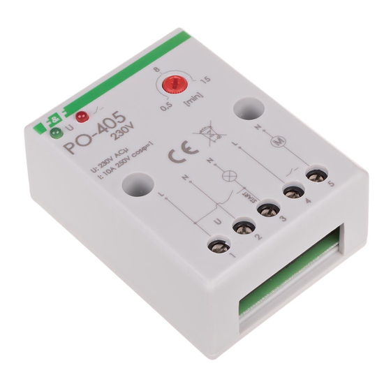
PO-405
Time relay,
with delayed drop-out
Do not dispose of this device in the trash along with other waste!
According to the Law on Waste, electro coming from households free of charge and can
give any amount to up to that end point of collec� on, as well as to store the occasion of
the purchase of new equipment (in accordance with the principle of old-for-new, regard-
less of brand). Electro thrown in the trash or abandoned in nature, pose a threat to the
environment and human health.
Purpose
The PO-405 time relay is used to maintain power supply to the
controlled receiver for a specific time after a loss of control volta-
ge, e.g. in bathroom ventilation systems where the fan (switched
on together with the lighting) is maintained for a specific time
after the lighting is switched off.
Functioning
Power supply to the relay is signalled by the illumination of the
green LED. Applying the control voltage to the relay causes its
operation and switching on of the voltage at the controlled re-
ceiver (signalled by lighting of the red LED).
After loss of control voltage the operation of the receiver is
maintained for the maintenance time "t" (potentiometer-ad-
justable). After time "t" the controlled receiver is switched off
automatically.
If the control voltage "S" is applied again before the set time has
elapsed, the relay performs its function from the beginning.
F&F Filipowski sp. j.
Konstantynowska 79/81, 95-200 Pabianice, POLAND
phone/fax (+48 42) 215 23 83 / (+48 42) 227 09 71
www.fif.com.pl; e-mail: biuro@fif.com.pl
- 1 -
Advertisement

Summary of Contents for F&F PO-405
- Page 1 Electro thrown in the trash or abandoned in nature, pose a threat to the environment and human health. Purpose The PO-405 time relay is used to maintain power supply to the controlled receiver for a specific time after a loss of control volta- ge, e.g. in bathroom ventilation systems where the fan (switched on together with the lighting) is maintained for a specific time after the lighting is switched off.
- Page 2 Diagram Mounting 1. Disconnect the power supply. 2. Fix the relay to the ground with 2 screws. 3. Connect to the circuit according to the diagram. 4. Use the knob to set the switching time. - 2 -...
- Page 3 Wiring diagram Terminals description relay power supply 230 V AC control signal input NO contact NO contact - 3 -...
- Page 4 Technical data power supply 195÷253 V AC maximum load current (AC-1) 10 A contact 1×NO backup time 1÷15 min. power indication green LED activation indication red LED power consumption 0.56 W temrinal 2.5 mm² screw terminals tightening torque 0.4 Nm working temperature -25÷50°C dimensions...


Need help?
Do you have a question about the PO-405 and is the answer not in the manual?
Questions and answers