Table of Contents
Advertisement
Quick Links
BIS-412-LED
Bistable relay,
Do not dispose of this device in the trash along with other waste! According to the Law on
Waste, electro coming from households free of charge and can give any amount to up to
that end point of collec� on, as well as to store the occasion of the purchase of new equip-
ment (in accordance with the principle of old-for-new, regardless of brand). Electro thrown
in the trash or abandoned in nature, pose a threat to the environment and human health.
Purpose
Electronic bistable pulse relay BIS-412-LED is designed to work
in a group system. The single relay allows you to control the re-
ceiver using momentary (bell) buttons, connected to local con-
trol inputs. Additionally, thanks to the central control inputs, it
is possible to group control of many receivers simultaneously.
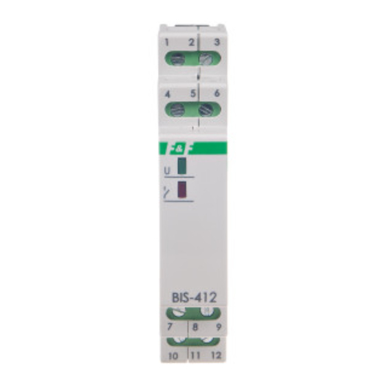
Functioning
The lighting of the green LED marked with the U symbol means
that the device is properly powered. The device can be control-
led from the level of local and central inputs.
Local control
The receiver is turned on (the relay contact is switched to po-
sition 7-10) after pressing any momentary button from the local
control group. The activation of the receiver is signaled by the
lighting of the red LED diode. Another pressing of the button
from the local control group will turn off the receiver (the con-
tact returns to position 7-12).
F&F Filipowski sp. j.
Konstantynowska 79/81, 95-200 Pabianice, POLAND
phone/fax (+48 42) 215 23 83 / (+48 42) 227 09 71
www.fif.com.pl; e-mail: biuro@fif.com.pl
group
- 1 -
Advertisement
Table of Contents

Related Manuals for F&F BIS-412-LED


Summary of Contents for F&F BIS-412-LED
- Page 1 Purpose Electronic bistable pulse relay BIS-412-LED is designed to work in a group system. The single relay allows you to control the re- ceiver using momentary (bell) buttons, connected to local con- trol inputs.
- Page 2 Central control ������ ��� ���������� (input no. 9) – pressing the momentary button connected to this input will always turn off the receiver (regardless of its previous state). The relay contacts will be swit- ched to position 7-12. This input allows you to centrally control a group of devices with a single button.
- Page 3 5. Connect the relay contact in series into the power supply cir- cuit of the controlled receiver/lighting (connect the power to terminal 7; connect the controlled receiver between terminal 10 and N-wire). 6. Connect the power supply. BIS-412-LED is compatible with backlit buttons. Contact configuration - 3 -...
- Page 4 Wiring diagram relay power supply 165÷265 V AC central control: ������ �� ���������� local control: ������ central control: ������ ��� ���������� 7-10 1×NO separated contact The control inputs may only be powered from the neu- tral wire (N). - 4 -...
- Page 5 Group system diagram - 5 -...
- Page 6 The maximum total backlight current of all connected buttons must not exceed 5 mA. Technical data power supply 165÷265 V AC contact separated 1×NO maximum load current (AC-1) 16 A (120 A/20 ms) control pulse current 5 mA activation delay 0.1÷0.2 s power indication green LED...
- Page 7 Power table tungsten halogen fluorescent energy-saving 2000 W 1250 W 1000 W 500 W 250 W The above data are indicative and will heavily depend on the design of a specific receiver (that is especially important for LED bulbs, energy-saving lamps, electronic transformers and pulse power supply units), switching frequency and operating conditions.
Need help?
Do you have a question about the BIS-412-LED and is the answer not in the manual?
Questions and answers