Table of Contents
Advertisement
Quick Links
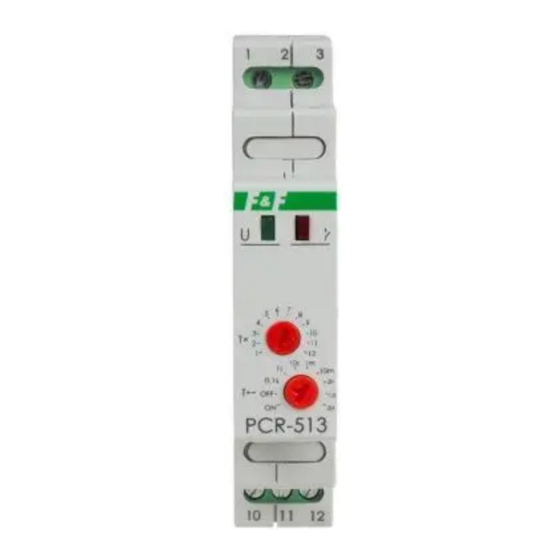
PCR-513
Time relay
with delayed activation
Do not dispose of this device in the trash along with other waste!
According to the Law on Waste, electro coming from households free of charge and can
give any amount to up to that end point of collection, as well as to store the occasion of
the purchase of new equipment (in accordance with the principle of old-for-new, regard-
less of brand). Electro thrown in the trash or abandoned in nature, pose a threat to the
environment and human health.
Purpose
The PCR-513 time relay is used for time control in industrial
and home automation systems (such as: ventilation, heating,
lighting, signaling, etc.).
Functioning
Operating mode: ON delay
After the supply voltage is switched on (the green LED "U" is on),
the contact remains in position 11-10 and the set operating time
counts down. After the preset time has elapsed, the contact swi-
tches to position 11-12 (the red LED
operating mode of the relay again you need to switch off the
power supply voltage and switch it back on.
F&F Filipowski sp. j.
Konstantynowska 79/81, 95-200 Pabianice, POLAND
phone/fax (+48 42) 215 23 83 / (+48 42) 227 09 71
www.fif.com.pl; e-mail: biuro@fif.com.pl
is on). To execute the
Advertisement
Table of Contents

Related Manuals for F&F PCR-513


Summary of Contents for F&F PCR-513
- Page 1 Electro thrown in the trash or abandoned in nature, pose a threat to the environment and human health. Purpose The PCR-513 time relay is used for time control in industrial and home automation systems (such as: ventilation, heating, lighting, signaling, etc.).
- Page 2 Working time setting Using the time range setting knob T↔, set one of the selected ranges, then using the time setting knob T×, set the selected va- lue on a scale from 1 to 12. The product of these values is equal to the operating time (for example: 1 m ×...
- Page 3 When the power supply of the relay is switched on, the system does not react to the change of time range and working time settings. Operation with the newly set time range and operating mode takes place after the power supply is switched off and back on.
- Page 4 Wiring diagram 1 2 3 T× 10s 1m 0,1s T↔ PCR-513 C C O O M M N N O O 10 11 12 N N C C - 4 -...
- Page 5 Description of terminals 230 V version: 1 (N), 3 (L) 24 V version: 1 (~/–), 3 (~/+) UNI version: 1 (~), 3 (~) relay power supply contact power input output: break contact (passive) output: closing contact (active) Technical data power supply 195÷253 V AC maximum load current (AC-1) contact...
- Page 6 Warranty The F&F products are covered by a warranty of the 24 months from the date of purchase. Effective only with proof of purchase. Contact your dealer or directly with us. CE declaration F&F Filipowski sp. j. declares that the device is in conformity with the essential requirements of The Low Voltage Directive (LVD) 2014/35/EU and the Electromagnetic Compatibility (EMC) Directive 2014/30/UE.
Need help?
Do you have a question about the PCR-513 and is the answer not in the manual?
Questions and answers