Advertisement
Quick Links
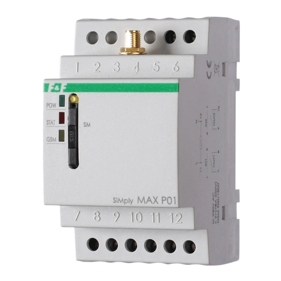
SIMply MAX P01
GSM remote control
Do not dispose of this device in the trash along with other waste! According to the Law
on Waste, electro coming from households free of charge and can give any amount to
up to that end point of collecti on, as well as to store the occasion of the purchase of new
equipment (in accordance with the principle of old-for-new, regardless of brand). Electro
thrown in the trash or abandoned in nature, pose a threat to the environment and hu-
man health.
Detailed instructions, the program for P01 Config and
the USB driver available for download at:
www.p01.fif.com.pl.
Purpose
SIMply MAX P01 relay with built-in GSM communicator is used
to remote control via mobile phone. It allows an easy way to
manage and monitor outputs status devices connected to the
inputs and outputs of the relay.
Features
» 2× ON/OFF control outputs (8 A 250 V AC);
» Time control of the outputs, example: for 30 s (1 s÷600 min.);
» 2× alarm inputs (12÷24 V AC/12÷30 V DC of direct
connection);
» Optional triggering with both the appearing and fading of the
signal (0/1);
» Notifications to 5 phone numbers for each input;
F&F Filipowski L.P.
Konstantynowska 79/81, 95-200 Pabianice, POLAND
phone/fax (+48 42) 215 23 83 / (+48 42) 227 09 71
www.fif.com.pl; e-mail: biuro@fif.com.pl
relay
12V
- 1 -
Advertisement

Related Manuals for F&F SIMply MAX P01


Summary of Contents for F&F SIMply MAX P01
- Page 1 USB driver available for download at: www.p01.fif.com.pl. Purpose SIMply MAX P01 relay with built-in GSM communicator is used to remote control via mobile phone. It allows an easy way to manage and monitor outputs status devices connected to the inputs and outputs of the relay.
- Page 2 » Queries about the status of inputs and outputs; » redefinition of the names of inputs and outputs, for example: IN1 -> PUMP; IN2 -> BREAK-IN; » Optional automatic replies about execution of the commands; » Optional automatic restore of the status of the outputs after power returns;...
- Page 3 6. Connect the receiver and control input signals in accordance with the description of the I/O connections and examples of implementation. 7. Switch on the power supply. Wiring diagram input 1 input 2 output 1 (separated contact) 9-10 output 2 (separated contact) 11-12 power supply Technical data...
- Page 4 Technical data (cont.) working temperature -10÷50°C terminal 2.5 mm² screw terminals tightening torque 0.4 Nm dimensions 3 modules (52 mm) mounting on TH-35 rail ingress protection IP20 GSM antenna connector antenna dimension 20×100 mm wire length 2.5 m mounting adhesive tape Warranty F&F products are covered by a 24-month warranty from the date of purchase.
Need help?
Do you have a question about the SIMply MAX P01 and is the answer not in the manual?
Questions and answers