Advertisement
Quick Links
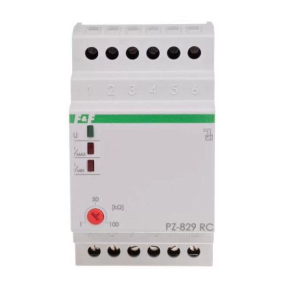
PZ-829 RC
Fluid level control relay,
2-position
Do not dispose of this device in the trash along with other waste!
According to the Law on Waste, electro coming from households free of charge and can
give any amount to up to that end point of collection, as well as to store the occasion of
the purchase of new equipment (in accordance with the principle of old-for-new, regard-
less of brand). Electro thrown in the trash or abandoned in nature, pose a threat to the
environment and human health.
Purpose
Fluid level control relays PZ-829 is devised to detect the pre-
sence of conductive liquids reaching the level of the sensor. It al-
low control MAX and MIN statues set by user of controlled fluid.
Functioning
After the liquid level decreases to MIN (i.e. electrodes MIN and
COM spaced), the MIN contact is switched to position 11-12,
whereas the MAX contact remains in position 8-9. On the other
hand, when the MAX liquid level is reached (MAX and COM elec-
trodes shorted), the relay's MIN contact will be switched to po-
sition 11-10, whereas the MAX into position 8-7.
Electrode probe connected with a cable with a wire dia-
meter of up to 1 mm² and a maximum length of 100 m.
F&F Filipowski sp. j.
Konstantynowska 79/81, 95-200 Pabianice, POLAND
phone/fax (+48 42) 215 23 83 / (+48 42) 227 09 71
www.fif.com.pl; e-mail: biuro@fif.com.pl
- 1 -
Advertisement

Related Manuals for F&F PZ-829 RC


Summary of Contents for F&F PZ-829 RC
- Page 1 Konstantynowska 79/81, 95-200 Pabianice, POLAND phone/fax (+48 42) 215 23 83 / (+48 42) 227 09 71 www.fif.com.pl; e-mail: biuro@fif.com.pl PZ-829 RC Fluid level control relay, 2-position Do not dispose of this device in the trash along with other waste!
- Page 2 Diagram Mounting 1. Take OFF the power. 2. Put on the relay on the rail in the switchgearbox. 3. Connect power to contacts 1-2 with marks. 4. Probe connect to relay by cable <1 mm². 5. Install the probes at heights corresponding to the fluid control levels.
-
Page 3: Wiring Diagram
Wiring diagram Tank filling - 3 -... - Page 4 Tank emptying - 4 -...
- Page 5 Technical data power supply 230 V AC maximum load current (AC-1) 2×16 A contact separated 2×NO/NC sensitivity (adjustable) 1÷100 kΩ contact switching delay for MIN level 1÷2 s for MAX level <5 s voltage of measuring outputs power signalling green LED work status signalling 2×...
-
Page 6: Warranty
Warranty F&F products are covered by a 24-month warranty from the date of purchase. The warranty is only valid with proof of purchase. Contact your dealer or contact us directly. CE declaration F&F Filipowski sp. j. declares that the device is in conformity with the essential requirements of The Low Voltage Directive (LVD) 2014/35/EU and the Electromagnetic Compatibility (EMC) Directive 2014/30/UE.
Need help?
Do you have a question about the PZ-829 RC and is the answer not in the manual?
Questions and answers