
Related Manuals for KODERA CASTING C373A


Summary of Contents for KODERA CASTING C373A
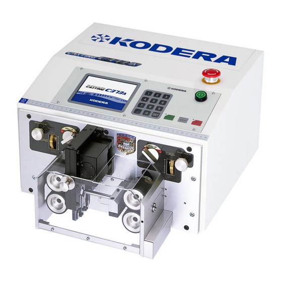
- Page 1 Instruction Manual Ver.10 Please read through very well before operating CASTING C373A. Caution must be strictly observed safety. It is recommended to keep this booklet nearby for your reference.
-
Page 2: Safety Precautions
Safety Precautions If you do not operate the device properly, it may result in failure or accident. Please read this instruction manual carefully before operating this device. ◎In this manual, safety instructions are indicated with “CAUTION” or “WARNING”. WARNING: If you do not observe this item properly, it may result in death or severe injury. CAUTION:... -
Page 3: Precautions For Installation
CAUTION:Contact your sales distributer for repair. Improper repair may result in electric shock or fire. CAUTION:The measure attached to this unit is only for reference. If you need precise measurement, take its measurement with your measure. CAUTION:Don’t modify this unit. ・Precautions for installation WARNING:Install this unit where it can support the weight and level for sure. -
Page 4: Table Of Contents
Contents Safety Precautions ・Precautions for Use ....................1 ・Precautions for installation ..................2 1.Installation ........................4 2.Name of componets and movement of each part ............9 3.Explanation of Components on the Operation Panel ..........10 4.Operation Panel 《Basic》 screen Standard Processing ..............11 《Motion》... -
Page 5: Installation
1.Installation 1.The machine is provided with wire guide pipe for round cable when it is delivered. So, In case the flat cable processing is required following preparation will be requid. DRG1 Right side wire guide 2. Loosen the screw "B" and remove the right-hand wire guide(DRG1) Cutting block SG uint DRG2... - Page 6 3. Using the screw hole "a" and "b", mount the flat wire guide set DRG3 Left-side wire guide plate 4. Loosen the screw "C"and remove the cutting block(DRG2). Since it is provided with a guide pin.gently pull the cutting block horizontally toward 5.
- Page 7 6. Loosen the screw "C" and remove the V-blade(lower)(DRG6). DRG6 DRG7 Lower Lower blade blade Lower blade guide 〔NOTE〕Sine the lower guide plate is for common use and is not necessary to remove, never loosen the screw "F". ・Using the screw "C" and additional 2pcs of the same (total 4pcs) mount the flat blade(lower)(DRG7) 7.
- Page 8 8. Befor mounting the flat guide onto the machine, adjust the height "h" according as the wire. DRG9 Loosen the scerw "A" and move the holding plate "B" up and down to adjust the height of "h"(DRG9). The inner guide plates have three different sizes, 1.5mm, 2mm and 2.5mm. Choose one out of them according as the wire size.
- Page 9 10. Adjustment of the flat wire guide set and flat guide. Flat guide Flat guide set DRG12 DRG11 Loosen the screw "A" and "B". Manually feed the wire into the flat cable guide parts and flat cable guide and adjust them so that the wire can be fed into the wire guides smoothly.
-
Page 10: Name Of Componets And Movement Of Each Part
2.Name of componets and movement of each part 【 Round wire type 】 ① Roller Up/Down knob,left ⑧ Drive Upper roller left ② Roller Up/Down knob,right ⑨ Drive Bottom roller left ③ Adj,knob for roller gap,left ⑩ Drive Bottom roller right ④... -
Page 11: Explanation Of Components On The Operation Panel
3.Explanation of Components on the Operation Panel Explanation of components The keys of this setting screen are displayed in (A)Setting screen parentheses 《 》. (B)POWER・・・Power ON/OFF switch button - (C)Keys for numerical value setting ( Ten keys) Keys for numerical value setting from [0] to [9] [ .] ・・When the numerical value less than 0 is input The keys of this setting screen are displayed in... -
Page 12: Operation Panel
4.Operation Panel 《Basic》 screen Standard Processing When not selecting ⑤~⑨ on the 《Motion》 screen(P.16). ①《Front Strip Length》:Setting of the stripping length of the front side insulation of the wire. ②《Front Half Strip Length》:Setting of the half stripping length of front side of the wire. Unit: ③《Total Length》:Setting of the cutting length of the wire. - Page 13 ⑪《Current Pieces》:Processed pieces of the wire. During processing, number of the 《 Current Pieces 》 ( processed pieces ) is increasing every second. When you want to clear the displayed number to “0”, press 《Current Pieces》 [0][SET]. ⑫《Batch Pieces》:Number of bundles For example, you can set this when you need 20 bundles of 50pieces totaling 1000 pieces.
- Page 14 How to set up the processing conditions Wire size 0.3sq Required Pieces 10pieces 1.The wire of the above picture is to be processed. Input ① 《Front Strip Length》 [SET] ② 《Front Half Strip Length》 [SET] ③ 《Total Length》 [7] [0] [SET] ④...
- Page 15 Depth of the blade when stripping should be as deep as possible but not damage the core. In case that the blade scratches the core wire, set the numerical value of 《Blade Move Back》 to open the gap of the blade which once cut in by the numerical value of the 《Blade Move Back》 and strip.
- Page 16 5.Setting the wire. A:Keep the UP/DOWN knob of the right side roller UP position. B:Manually insert the wire from the right side wire guide, right side roller, guide pipe and a bit left side of the blades (too much insertion will be a cause for an error), and put the right side roller down.
-
Page 17: Motion》 Screen
《Motion》 Screen From any screen , if 《Motion》 is touched, this screen will be displayed. ①《Motion》:It will light up when the setting is that optional extras are not equipped. ②《Marker》:This key is set when marker which marks on the wire is attached. (See P.24)... - Page 18 ⑩《Rollup 2》: Use this function when an optional left roller UP/DOWN machine is attached. ⑪《Rollup 1》: Use this function when an optional right roller UP/DOWN machine is attached. When you select 《Rollup 1》 & 《Rollup 2》, 《 Up 》 keys are displayed on the Basics screen.
- Page 19 [Addition] Core diameter in a front and a back end can be established separately. Setting of ≪Core Diameter≫ and ≪Blade Move Back≫ of a ≪Basics≫ screen is usually applied to a Front and a back end likewise, but when You’d like to establish it separately respectively, it's used.
-
Page 20: Basics》 Screen At 《Short Mode
《Basics》 screen at 《Short Mode》 Select 《Short Mode》 on the 《Basics》 screen(P.16). When the length of the remaining wire insulation is shorter than 47.9mm The left roller should be UP. When processing a short length wire, it is possible to perform half- stripping. -
Page 21: Basics》 Screen At 《Divide Strip
《Basics》 screen at 《Divide Strip》 Select 《Divide Strip》 at 《Motion》 screen (P.16). Divide strip processing, please be sure to enter the Half-strip length. ①《Front Strip Length》:Setting of the stripping length of the front side insulation. ②《Front Half Strip Length》:Setting of the half-stripping length of front side of the wire. -
Page 22: Basics》 Screen At 《Double Strip
《Basics》 screen at 《Double Strip》 Select 《Double Strip》 on the 《Motion》 screen (P.16). ①《Front Strip Length》:Setting of the stripping length of the front side insulation. ②《Front Hal Strip Length》:Setting of the half stripping length of front side of the wire ③Setting of the insulation length of front side which is not stripped. -
Page 23: Basics》 Screen At Sheath Strip (Half Stripping Of Core Wire)
《Basics》 screen at Sheath Strip (half stripping of core wire) Select ⑧ on the 《Motion》screen (P.16). At above Figure, Semi-Strip scene are displayed so that setting becomes easily understandable. But it is not displayed on the screen of the device. ①《Front Strip Length》:Setting of the stripping length of the front side insulation. -
Page 24: Basics》 Screen At Sheath Strip (Outside Insulation Half Stripping)
《Basics》 screen at Sheath Strip (outside insulation half stripping) Select ⑨ on the 《Motion》 screen (P.16). At above figure, half-stripping scene is displayed so that setting becomes easily understandable. But it is not displayed on the screen of the device. ①《Front Strip Length》:Setting of the stripping length of the front side insulation. -
Page 25: Motion》 Screen At 《Marker
《Motion》 screen at 《Marker》 Select《marker》on the 《Motion》screen (P.16). Set these functions when you use marker. On the above screen, all of the items in marker are displayed to explain. Depending on the setting, items to be displayed change. ①《Both Ends Marking/Equally-Spaced Marking》:Setting how to mark on the wire which is finished. - Page 26 ⑦《Specified Number》:When 《Number of Specified》 at ② has been selected, set how many times to mark on a wire at even intervals. ⑧《Print Interval》《Rear Print Point》: When 《Both Ends Marking》《Separate Marking》 have been selected, 《Rear Print Point》is displayed. When others are selected, display is changed to 《Print Interval》. Rear Print Point:Setting point to print at the rear side.
-
Page 27: Machine Adj》 Screen
《Machine Adj》 Screen From any screen, by touching 《Machine Adj》, it will be displayed. ①《Language Selection》:Selection of language displayed on the operation panel of C373A. ②《Memory Write》: From “0” to “500” ③《Memory Read》: From “0” to “500” ④《Total Length Correction》:Only the cutting length is corrected. ⑤《Discharge Time》:... -
Page 28: In Case Of Tube Or Cutting Only
5.In case of tube or cutting only Input 《Total Length》 only, and 《Front Strip Length》, 《Front Half Strip Length》, 《Rear Strip Length》 and 《Rear Half Strip Length》 shall be all “0” Any numerical values are acceptable for 《Core Diameter》 and 《Blade Move Back》. Setting of the pieces and gap adjustment are required. -
Page 29: Replacing The Guide Pipe
8.Replacing the guide pipe (1) Remove screw "A" and pull SG unit off of the holder. (2) Loosen screw "C" and screw "B", then guide pipe can be removed. To mount the guide pipe, insert the guide pipe so that the groove on the guide pipe is aligned with the tip of screw 'B'. - Page 30 -Remove screw B and then the lower blade. (See Fig.4) Upper Cutter Lower cutter Lower cutter holder C Fig. 4 -Remove screw C, and pull out the upper blade in the direction of the blade. (See Fig.5). -To mount the blade, first insert the upper blade into the upper blade holder in reverse direction to the arrow as shown in Fig.5, and fix it with screw C.
-
Page 31: Maintenance And Inspection
11.Maintenance and inspection Allways turn the illuminated ON/OFF switch of the C373A to OFF prior to carrying out any conversion, maintainance or inspection work on the machine. BLADE BLOCK -Remove screw A and pour grease into hole A. -Fasten screw A. *To prevent the blade block from seizing, check that grease is always supplied. -
Page 32: Trouble Shooting
12.Trouble Shooting Symptom Where to check How to repair 1)Wire automatically. Rollers don’t rotate. Isn’t it 《Short Mode》? Clear the 《Short Mode》. (See P.16) It starts processing as Is the left side roller under the Make it DOWN. soon as it starts. condition of UP?... - Page 33 Symptom Where to check How to repair The numerical value is set at Replacement of the blade.(See 《Half Strip Length》? P,28) The blade is worn away or Replacement of the blade.(See chipped off? P,28) The position of the blade is out Replacing the blades do.
-
Page 34: List Of Main Optional Parts
13.List of main optional parts C373A figure name order-No. note Guide pipe 2φ C353-117-A Guide pipe 3φ C353-117-B Guide pipe 4φ C353-117-C Guide pipe 5φ C353-117-D Guide pipe 6φ C353-117-E Guide pipe 7φ C353-117-F Guide pipe 8φ C353-117-G standard Guide pipe 9φ C353-117-H Guide pipe 10φ... - Page 35 C373AF figure name order-No. note Flat guide pipe adjustment ASSY C353F-17 (Thickness plare 1.5mm) Flat guide pipe adjustment ASSY C353F-18 (Thickness plare 2.0mm) Flat guide pipe adjustment ASSY C353F-19 (Thickness plare 2.5mm) 4pcs,=1set Roller coarse rough C353-121-A standard Roller coarse fine C353-121-B 4pcs,=1set Roller sand shot...
-
Page 36: Guideline For Selecting The Guide Pipe
14.Guideline for selecting the guide pipe AVSS Final OD Guide Pipe Sq Final OD Guide Pipe Sq Final OD Guide Pipe 1.8mm 3 φ 2.0mm 3 φ 1.5mm 2 φ 2.2mm 3 φ 0.85 2.2mm 3 φ 1.7mm 3 φ 0.85 2.4mm 3 φ... -
Page 37: Specifications
Specifications Model C373A Outer Dimensions W:430mm × D:510mm × H:265mm Weight 33 kg Power Source AC 100 V ~ 240 V ±10% 50Hz/60Hz Power Consumption 56 W(rating) 300 W(max.) At AC100V Air supply Approx. 9 liter/min. 0.5Mpa (Use clean dry air.) 0.1mm ~...
Need help?
Do you have a question about the CASTING C373A and is the answer not in the manual?
Questions and answers