Table of Contents
Advertisement
Quick Links
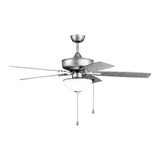
Outdoor Pro Plus 52" with Light Kit
Installation Guide
For models:
OP104
OP119
OP211
LISTED
For
Wet Location
E192641
net weight of fans: 19.29 lb (8.75 kg)--OP104
18.41 lb (8.35 kg)--OP119
18.96 lb (8.60 kg)--OP211
READ THESE INSTRUCTIONS AND
SAVE THEM FOR FUTURE USE
Table of Contents:
Safety Tips. pg. 2
Unpacking Your Fan. pg. 3
Parts Inventory. pg. 3
Installation Preparation. pg. 4
Hanging Bracket Installation. pg. 4
Fan Assembly. pgs. 5 - 6
Wiring. pg. 7
Canopy Assembly. pg. 8
Blade Assembly. pg. 8
LED Light Kit Assembly Option. pg. 10
Testing Your Fan. pg. 12
Troubleshooting. pg. 13
Parts Replacement. pg. 13
Warranty. pg. 13
page 1
PRINTED IN CHINA
Advertisement
Table of Contents

Related Manuals for Craftmade OP104


Summary of Contents for Craftmade OP104
-
Page 1: Table Of Contents
Testing Your Fan. pg. 12 Troubleshooting. pg. 13 LISTED Parts Replacement. pg. 13 Wet Location Warranty. pg. 13 E192641 net weight of fans: 19.29 lb (8.75 kg)--OP104 18.41 lb (8.35 kg)--OP119 18.96 lb (8.60 kg)--OP211 PRINTED IN CHINA page 1... -
Page 2: Safety Tips
(2) this LED light kit must accept any interference received, including interference that may cause undesired operation. Distributed by: Craftmade, 650 S. Royal Lane, Coppell, TX, 75019; 1-800-486-4892 NOTE: The important safety precautions and instructions appearing in the manual are not meant to cover all possible conditions and situations that may occur. -
Page 3: Unpacking Your Fan
(in hardware pack). 1 piece g. blade arm. 5 pieces Light Kits by Model Number: h. 3-light kit fitter. 1 piece OP119 OP104 OP211 h1. shade. 3 pieces h2. 7 watt medium base LED bulb. 3 pieces i. LED light kit. 1 piece i1. -
Page 4: Installation Preparation
3. Installation Preparation. blade edge To prevent personal injury and damage, inches ensure that the hanging location allows the 7 feet (76cm) blades a clearance of 7 feet (2.13m) from the (2.13m) floor and 30in. (76cm) from any wall or obstruction. -
Page 5: Fan Assembly. Pgs
5. Fan Assembly. Remove hanging ball from downrod provided stop pin by loosening set screw on hanging ball. Lower set screw hanging ball and remove stop pin and then slide hanging ball off of the downrod. hanging ball [Refer to diagram 1.] Loosen yoke set screws and nuts at top of motor housing. - Page 6 5. Fan Assembly. (cont.) Thread wires through hanging ball and then slide hanging ball over downrod--the top of the weatherproof downrod should be noted as having a set screw hanging hole; use this hole when setting the set screw. ball cover Insert stop pin into top of downrod and raise electrical wiring hanging ball.
-
Page 7: Wiring
6. Wiring. WARNING: Turn off circuit breakers to current fixture from breaker panel and be sure switch is turned to the OFF position. white supply wire CAUTION: Be sure outlet box is properly grounded ground and that a ground wire (GREEN or Bare) is present. (green or bare) black supply wire Make sure all electrical connections comply with... -
Page 8: Canopy Assembly
7. Canopy Assembly. hanging bracket Locate 2 screws on underside of hanging bracket and remove screw closest to the open end of the hanging bracket. Partially loosen the other screw. Lift canopy to hanging screw bracket. Place rounded part of slotted hole in canopy over loosened screw in hanging canopy bracket and push up. -
Page 9: Light Kit Assembly, 3-Light Option
9. Light Kit Assembly, 3-light Option. *For Model OP104 Remove 3 screws from top of light kit fitter. motor housing Locate BLUE (or BLACK) and WHITE wires in switch housing labeled FOR LIGHT KIT CONNECTION. Remove and discard plastic that holds these 2 wires together. -
Page 10: Led Light Kit Assembly Option
10. LED Light Kit Assembly Option. *For Model OP119 Remove 3 screws from switch housing cap motor housing (at top of LED light kit). Locate BLUE (or BLACK) and WHITE wires in switch housing labeled FOR LIGHT KIT CONNECTION. Remove and discard plastic that holds these 2 wires together. -
Page 11: Light Kit Assembly, 1-Light Option
11 Light Kit Assembly, 1-light Option. *For Model OP211 Remove 3 screws from switch housing cap (at top of light kit fitter). Locate BLUE (or BLACK) and WHITE wires in switch housing labeled LIGHT. Remove and discard plastic that holds these 2 wires together. Next, locate WHITE and BLACK wires in light kit motor fitter labeled FOR LIGHT. -
Page 12: Testing Your Fan
12. Testing Your Fan. It is recommended that you test fan before finalizing installation. Restore power from circuit box and light switch (if applicable). Test fan speeds with the pull chain on the switch housing. Start at the OFF position (no blade movement). -
Page 13: Troubleshooting
Service at 1-800-486-4892 to arrange for return of fan. 1. Check wall switch to fan. Return fan, shipping prepaid, to Craftmade. We will repair 2. Verify that reverse switch is set completely in or ship you a replacement fan, and we will pay the return either direction.
Need help?
Do you have a question about the OP104 and is the answer not in the manual?
Questions and answers