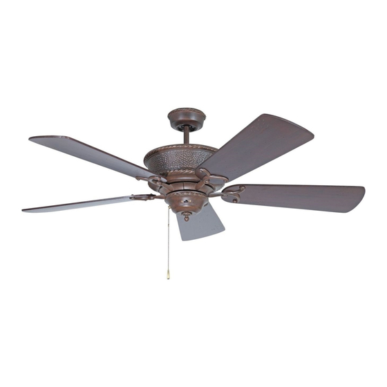
Craftmade CH52 Installation Instructions Manual
Craftmade ceiling fans installation instructions
Hide thumbs
Also See for CH52:
- Installation instructions manual (23 pages) ,
- Specifications (1 page) ,
- Installation instructions manual (23 pages)
Advertisement
Advertisement
Table of Contents

Summary of Contents for Craftmade CH52
- Page 1 WD52 LT52 Installation Instructions Model: CH52, RT52, 5 5L52, TL52 LT52,...
-
Page 2: Before Assembly
Read and Save These Safety Precautions What l'Ou Have Turn off electricity at main switch befote wiring or servicing fan in order to avoid Parts Quantity flJ--2 possible electrical shock. All wiring must be in accordance with the National Electric Code (ANSIINFPA 70- __ 1 1999) and local electrical codes. - Page 3 Screws (51) Downrod Installation B. Angle Mount (Normal Ceilings) Canopy Screws (52) Craftmade Part #45AD (see dealer) Step 5 IMPORTANT: If using the angle mount method, check to make sure the ceiling angle is not steeper than 35°. Angles greater...
- Page 4 For added security, attach safety cable from fan unit to "]" hook (510) in Position downrod so the hole in the downrod aligns with the hole in the outlet box. 5ecure by looping zip tie (511) through safety cable and "]" coupling on the motor.
- Page 5 Attach canopy (3) to the 1. Connect fan wires to ceiling wires: white fan wire to white outlet wire, mounting bracket by placing black to black and green to green. Wire connectors (S6) are ptovided for screws (S2) into slot in canopy. your convenience.
-
Page 6: Step 11 5 Blade Installation
Step 11 5 Blade Installation 1. To install the Switch Housing Assembly (8), locate both modular Remove rubber cushions, saving motor screws for blade installation. wiring plugs (A) and (B). One extends from the mounting plate (E) on Using motor screws (S5) provided, line up holes from the blade arm with bottom of fan body and one extends from the Switch Housing (8). -
Page 7: Optional Light Kit Installation
Optional Light Kit Installation Remove three screws from side of switch hub (as shown in figure below). Connect black and blue (if provided) fan wires to black outlet wire. Remove hub cover from hub and pop out center plug. Carefully thread Connect white fan wire to white outlet wire and green grounding lead wires from light kit through the center hole in hub cover. -
Page 8: Common Problems
2. Check that all blade holders are screwed firmly into motor. 3. Check the weight of blades. All our blades are weighed on electronic Modelos: CH52, RT52, S scales. The weight is marked on the reverse side of the fan blade near SL52, TL52, the motor end.


Need help?
Do you have a question about the CH52 and is the answer not in the manual?
Questions and answers