
Related Manuals for janitza UMG 800


Summary of Contents for janitza UMG 800
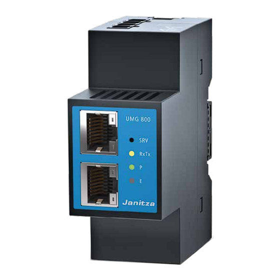
- Page 1 Modularly expandable energy analyzer UMG 800 User manual and technical data Janitza electronics GmbH Vor dem Polstück 6 35633 Lahnau | Germany Support: +49 6441 9642-22 info@janitza.com | www.janitza.com...
- Page 2 The German version is the original edition of the documentation. INFORMATION The content of this document reflects the measurement device firmware version 1.7.0, which was current at the time of creation. Check for the presently current version (www.janitza.com) and keep the measurement device firmware up to date!
- Page 3 Nonetheless, we wish to point out that updates of this document are not always possible at the same time as technical refinements are implemented in our products. Please see our website under www.janitza.com for the current version. Please see our website under www.janitza.com for the current version.
-
Page 4: Table Of Contents
UMG 800 www.janitza.com TABLE OF CONTENTS 1. Information on the device and the user manual Disclaimer Copyright notice Technical changes About this user manual Defective device/disposal 2. Safety Display of warning notices and safety information Hazard levels Product safety Dangers when handling the device... - Page 5 UMG 800 4. Structure of the device Controls, display elements and interfaces (views without terminals) Side views (without terminals) Rear view (without terminals) Identification of the device (rating plate) 5. Mounting Installation location Bus connector DIN rail mounting of the meter 6.
- Page 6 UMG 800 www.janitza.com 10. Communication via the interfaces 10.1 Ethernet interfaces - Modbus TCP 10.2 Connection options “Switched mode” and “Dedicated mode” 10.2.1 “Switched mode” connection option 10.2.2 “Dedicated mode” connection option 10.3 OPC UA protocol 10.4 RS-485 interface (fieldbus) 10.4.1 Shielding 10.4.2...
- Page 7 UMG 800 11.2.4 Profile - User-defined measurement group 11.2.5 Configuration of the Virtual Meter using the device homepage 11.2.6 Measured values of the virtual measurement groups 11.2.7 Configuration in the GridVis software 12. Connection example 13. Dismounting 14. Device homepage 14.1...
- Page 8 UMG 800 www.janitza.com 16. Error messages 16.1 Overrange 16.2 Display of overrange on external display 16.3 Procedure in the event of a malfunction 17. Technical specifications 17.1 Technical data 17.2 Performance characteristics of functions 17.3 Parameter and Modbus address list 17.4 Information on saving measured values and configuration data 18.
- Page 9 UMG 800...
-
Page 10: Information On The Device And The User Manual
· the “Safety information” supplement. · if applicable, the usage information of the integrat- Copyright notice ed modules and components of your meter and © 2024 - Janitza electronics GmbH - Lahnau. module topology (e.g. current and voltage trans- formers). All rights reserved. -
Page 11: Defective Device/Disposal
UMG 800 Defective device/disposal Before sending defective devices, modules or components back to the manufacturer for testing: · contact the manufacturer's Support department. · send devices, modules or components complete with all accessories. · when doing so, please bear the terms for transpor- tation in mind. -
Page 12: Safety
UMG 800 www.janitza.com Safety The chapter on Safety contains information which Product safety must be observed to ensure your personal safety The devices, components and modules reflect and avoid material damage. current engineering practice and accepted safety standards, but hazards can arise nonetheless. -
Page 13: Dangers When Handling The Device
· Hazardous voltages can be present in all cir- · Do not use Janitza meters, modules or compo- cuitry parts that are connected to the power nents for critical switching, control or protection supply. -
Page 14: Electrically Qualified Personnel
UMG 800 www.janitza.com The measurement device has an integrated self-re- Electrically qualified personnel setting fuse, the resistance of which increases in the To avoid bodily injury and material damage, only event of high electrical currents (e.g. a short circuit) electrically qualified personnel are permitted to work due to self-heating. -
Page 15: Safety Information For Handling Transformers
For Janitza measurement devices, modules and components, use only “transformers for measur- ing purposes” which are suitable for the energy monitoring of your system! Please note Sect. “3.11 Transformers”... -
Page 16: Product Description
UMG 800 www.janitza.com Product description Device description · measures in medium and high-voltage networks via voltage transformers. · is suitable for fixed switchboard cabinets or small distribution boards, in any mounting orientation. · is not a protective device against electric shock! ·... -
Page 17: Incoming Goods Inspection
UMG 800 Incoming goods inspection ATTENTION Safe and trouble-free operation of this measurement Improper handling can damage the measurement device (with its modules and components) presup- device (possibly also modules and components) poses proper transport, storage, setup and assembly and lead to material damage! -
Page 18: Performance Characteristics
UMG 800 www.janitza.com Performance characteristics General Measurement · Space-saving DIN rail meter with dimensions W: 36 m · Measurement in TN, TT and IT networks. m (2 HP) x H: 90 mm x D: 76 mm. · Measurement in networks with nominal voltages up to · For mounting on 35 mm DIN rail (for types see the L-L 480 V and L-N 277 V. -
Page 19: Module Slots And Janbus System Limits
· Connect the device and the radio/television receiv- er in different circuits. 2 x Module 800-DI14 · if necessary, contact Janitza support or a radio/ + 6 x Module CT8-LP television technician. 8 module slots required on the basic device. -
Page 20: Scope Of Delivery
3303912 Installation manual DE/EN 3.11 Transformers 3303342 “Safety Information” supplement For Janitza measurement devices, modules and 5238250 Accessory pack components, use only transformers designed for Tab. Scope of delivery measuring purposes! Please observe the warnings in this regard in Sect. “7. Installation” on p. 32 The device is delivered with the required terminals (accessory pack). -
Page 21: Operating Concept
Sect. “10.6 USB interface” on You can use the GridVis network analysis software p. 48). available at www.janitza.com to configure your 2. Operation via the Ethernet interfaces A (DHCP measurement device and read out data for analysis. mode) and B (static IP address) in conjunction To do so, connect a PC to your measurement device... -
Page 22: Measured Values (With Voltage Component)
UMG 800 www.janitza.com 3.15.3 Measured values (with voltage component) Measured values Device/system Channel Average Min. value Max. value (with voltage component) related related value ü ü ü Frequency ü Rotating field direction U System Measurement of positive, negative, zero se- ü... - Page 23 UMG 800...
-
Page 24: Structure Of The Device
UMG 800 www.janitza.com Structure of the device Controls, display elements and interfaces (views without terminals) Top view Front view Bottom view... - Page 25 UMG 800 Item Function/Designation Supply voltage connection. RS-485 interface. DIP switch for RS-485 termination - see Sect. “10.4 RS-485 interface (fieldbus)” on p. 45 Ethernet interface (RJ45) - Ethernet B - static mode (factory setting: IP address:10.10.10.200) Ethernet interface (RJ45) - Ethernet A - DHCP mode (factory setting: Dedicated mode)
-
Page 26: Side Views (Without Terminals)
UMG 800 www.janitza.com Side views (without terminals) Rear view (without terminals) Bottom bolt JanBus interface (bus connector connection, module connection) Bottom bolt INFORMATION When the device is delivered, the bus connectors are already plugged into the JanBus interface! -
Page 27: Identification Of The Device (Rating Plate)
• 5238001 1800/0001 Aux: 24V 2.5W (max. 14W) MAC: 00:0E:6B:20:00:00 Made in Germany • www.janitza.com Item Designation Description MAC address Unique identification of the device in a computer network. Supply voltage, power consumption and max. power consumption (with modules and Operational data ext. -
Page 28: Mounting
· force the contacts into the bus connector · Return defective measurement devices to sockets! Janitza electronics GmbH in accordance with the shipping instructions for air or road freight (complete with accessories). · All usage information is also available as a download at www.janitza.com. -
Page 29: Bus Connector
UMG 800 Bus connector Contacts of the bus connector INFORMATION The measurement device is supplied with the appropriate bus connectors. Please also note the following before setting up a meter and module Sockets topology for the bus connector · Mount the bus connector! ·... - Page 30 UMG 800 www.janitza.com 3. Press your meter with the bus connector onto E.g. current measuring or Basic device digital input modules the DIN rail frontally until the bottom bolts engage (click). Meter with mounted bus connector DIN rail Fig.: Example of a meter and module topology Internal bus 6.
-
Page 31: Grid Systems
UMG 800 Grid systems Suitable grid systems and maximum rated voltages according to DIN EN 61010-1/A1: Three-phase 4-conductor systems Three-phase 3-conductor systems with grounded neutral conductor with grounded phase : 270 V / 480 V 480 V : 270 V / 480 V 480 V Three-phase 4-conductor systems... -
Page 32: Installation
260 V / 440 V death or to material damage! · Do not use Janitza measurement devices or com- Maximum rated voltage of the 277 V / 480 V ponents for critical switching, control or protection... -
Page 33: Circuit Breaker
UMG 800 Supply voltage 230V/400V 50/60Hz WARNING Risk of injury due to electrical voltage! Severe bodily injury or death can result from: · Touching bare or stripped leads that are ener- gized. · Device inputs that pose a hazard when touched. -
Page 34: Voltage Measurement
UMG 800 www.janitza.com Voltage measurement UMG 800 The device has 4 voltage measurement inputs and is suitable for various connection variants. WARNING Risk of injury or damage to the device due to elec- PELV trical voltage and improper connection! (grounded Failure to comply with the connection conditions for... -
Page 35: Overvoltage
UMG 800 7.4.1 Overvoltage The voltage measurement inputs are designed for measurements in low-voltage networks in which nominal voltages occur as described in Sect. “17. Technical specifications” on p. 94. Information on the rated surge voltages and over- voltage categories can also be found in the technical data. -
Page 36: Connection Variants For Voltage Measurement
UMG 800 www.janitza.com 7.4.3 Connection variants for voltage measurement Three-phase 4-conductor system Three-phase 3-conductor system Three-phase 4-conductor system without voltage Three-phase 3-conductor system with voltage transformer transformer Three-phase 4-conductor system Three-phase 3-conductor system Three-phase 4-conductor system with voltage transformer Three-phase 3-conductor system (asymmetrical load) -
Page 37: Configuring Voltage Transformers
UMG 800 7.4.4 Configuring voltage transformers Configure the voltage transformers on the measure- ment device: 1. With a commissioning file that is loaded via the USB interface. 2. Via the function buttons of an external display (e.g. RD 96) under Menu > Configuration >... -
Page 38: Operation And Commissioning
UMG 800 www.janitza.com Operation and commissioning Operating options for the meter Controls and display elements After mounting and installation, the measurement device has the following operating options, e.g. for commissioning, configuration and displaying mea- Ethernet A surement data: · For commissioning, a USB storage medium (FAT32... -
Page 39: Led Display Elements
UMG 800 8.2.2 LED display elements LED status of connected modules During the initialization (start) and operation of meter Item Description and module topologies, the LEDs of connected mod- ules show and signal various states (for more infor- RxTx (Receive data, Transmit data) - LED (yel- mation, see the usage information for the modules). -
Page 40: Pc Connections
UMG 800 www.janitza.com PC connections The most common connection methods for commu- 2. Connection as a client device (formerly master) nication of the measurement device with a PC (with with gateway function and downstream RS-485 the GridVis software installed) are described below. - Page 41 UMG 800...
-
Page 42: 10. Communication Via The Interfaces
UMG 800 www.janitza.com 10. Communication via the interfaces 10.1 Ethernet interfaces - Modbus TCP INFORMATION ATTENTION The following options are available for configuring the Ethernet interfaces: Material damage due to security vulnerabilities in · Configuration on the device homepage (for more programs, IT networks and protocols. -
Page 43: Connection Options "Switched Mode" And "Dedicated Mode
UMG 800 10.2 Connection options “Switched mode” and 10.2.1 “Switched mode” connection option “Dedicated mode” With this connection option, several devices (hard- ware components) are connected with each other in In addition to integrating the measurement device series: with the Ethernet interfaces A and B, the following... -
Page 44: Opc Ua Protocol
UMG 800 www.janitza.com 10.3 OPC UA protocol Data is transferred using the OPC UA protocol via the Ethernet interfaces of your measurement device. INFORMATION · Consult your network administrator for the correct Ethernet network settings for your measurement device. · Information on connecting your measurement de- vice and its communication with the software can be found in the corresponding help formats (e.g. -
Page 45: Interface (Fieldbus)
UMG 800 10.4 RS-485 interface (fieldbus) INFORMATION The measurement device has a 3-pin RS-485 inter- · If you use the measurement device as a client de- vice (formerly master device), always position it at face (serial) for communication via the Modbus RTU the beginning or end of a bus segment! Terminate protocol. -
Page 46: Shielding
UMG 800 www.janitza.com 10.4.1 Shielding 10.4.2 Termination resistors/Termination For connections via the interfaces, use a twisted The device contains an integrated termination resis- and shielded cable and observe the following for the tor (S1). Terminate the beginning and end of your bus... -
Page 47: Bus Structure (Bus Segment)
UMG 800 10.4.3 Bus structure (bus segment) · Devices with bus termination switched on must be powered. In a bus structure: · It is recommended that the client device (formerly · Connect all devices in line. master device) be placed at the end of a segment. -
Page 48: Usb Interface
UMG 800 www.janitza.com 10.6 USB interface The measurement device has a USB interface (type A) for connecting a compatible: 1. USB storage medium. 2. External displays, e.g. the RD 96 (available separately). UMG 800 USB storage medium, e.g. with the network configuration file USB cable Fig. -
Page 49: Reading A Network Configuration File (Of Ethernet Interfaces A And B)
"DhcpActive": false, RD 96” on p. 50). "Gateway": "10.10.10.1", "Ip": "10.10.10.200", The latest firmware for the measurement device "Netmask": "255.0.0.0" can be found at www.janitza.com. "dnsAutomaticFlag": true, "dnsServer": [ 10.6.3 Reading a network configuration file (of „“, Ethernet interfaces A and B) „“,... -
Page 50: Writing (Saving) A Network Configuration File
UMG 800 www.janitza.com 10.6.4 Writing (saving) a network configuration file Regardless of whether the measurement device has a “Network configuration file with or without se- rial number” on the USB storage medium, it always saves its current network configuration file on the networkinfo-<sn>. -
Page 51: External Display Rd 96 - Optional
UMG 800 10.6.6 External display RD 96 - optional Use the separately available RD 96 display (see Sect. “3.9 Accessories” on p. 20) to visualize measure- ment data and configure the following functions of the measurement device (menu > Configuration): · Ethernet A ·... -
Page 52: Overview Of Menu Displays With External Display (E.g. The Rd 96)
UMG 800 www.janitza.com 10.7 Overview of menu displays with external Current - display (e.g. the RD 96) only with current measuring modules Current INFORMATION 1. Modules 1-4 The following overview of the menu displays shows: · No specific use case and may vary depending on x. - Page 53 UMG 800 Energy Digital I/O Status - only with digital input module Active energy Digital I/O status modules 1. Modules 1-4 (Digital I/O status, modules) x. Module xx Reactive energy 1. Modules 1-4 Configuration x. Module xx Ethernet config. A (Ethernet config. A) Apparent energy IP config.
-
Page 54: System Information
UMG 800 www.janitza.com System information Display Language Basic device Standby delay Serial no. Brightness Standby mode IP address System Date HW version Reboot SW version Time SW build Date Modules Reset Module 1 - only with modules Factory settings Configuration Module x Min./Max./Avg. - Page 55 UMG 800...
-
Page 56: 11. Configuration
RMS value Measurement of frequency events INFORMATION · Frequency change Fundamental explanations of “events and transients” · Underfrequency can be found in the document “Energy Supply Qual- · Overfrequency ity Characteristics – Power Quality Solutions from Janitza” and on www.janitza.com. -
Page 57: Event And Transient Recording
UMG 800 11.1.3 Event and transient recording The event recording includes the average, minimum and maximum value, as well as the start and end When an event or transient occurs, the measurement time and, in the case of longer events, the waveform device records half-waves (half-cycles) and data at the beginning and end of an event as well. -
Page 58: Configuration Of The Waveform For Events And Transients
UMG 800 www.janitza.com 11.1.4 Configuration of the waveform for 11.1.5 Half-wave RMS values for events events and transients Within half-waves (10 ms), the measurement device You can configure the recording length (lead time compares the measured value (effective) with the and lag time - see Sect. “11.1.3 Event and transient limit value configured by the user (device homepage recording”... -
Page 59: Update Time For Transients
UMG 800 11.1.6 Update time for transients Update time for Update time for Parameter/ the half-wave the half-wave If a measured value exceeds the configured limit val- Fault RMS values at RMS values at ue (device homepage or GridVis), the measurement f = 50 Hz... -
Page 60: Flicker
UMG 800 www.janitza.com 11.1.8 Flicker The measurement device requires the fundamen- tal network values for the voltage and frequen- cy-dependent measurement and calculation of the flicker values (flicker measurement according to DIN EN61000-4-15:2011). The device user configures the fundamental network values (nominal values) in the device configurator in the GridVis software using the following entries: Fig. - Page 61 UMG 800...
-
Page 62: Virtual Meter
UMG 800 www.janitza.com 11.2 Virtual Meter 11.2.1 Application examples With the Virtual Meter function, the meter user can Configuration examples for current measurements assign channels of real measurement points to a with the virtual meter in various meter and module virtual meter, for example, to perform summation... - Page 63 UMG 800 11.2.2 Profile - Measurement group of 3 The following figure shows an example of the profile · The neutral conductor current is calculated from the “Measurement group of 3” in the Virtual Meter sum values L1, L2, L3.
- Page 64 UMG 800 www.janitza.com Example 2 shows the profile “Measurement group of 3” in the Virtual Meter function using a meter and module topology of the basic device with 3 800-CT8-A current measuring modules: Basic device 1. 800-CT8-A 2. 800-CT8-A 3. 800-CT8-A...
- Page 65 UMG 800 U1 U2 U3 Example 3: Example 3 shows the profile “Measurement group of 3” using a meter and module topology of the basic device with 4 800-CT24 current measuring modules: For this example, the user configures the maximum number of up to 32 virtual measurement groups in the GridVis software or on the device homepage.
- Page 66 UMG 800 www.janitza.com 11.2.3 Profile - Measurement group of 4 The following figure shows an example of the profile · Channel L4 is for a single measurement or for mea- “Measurement group of 4” in the Virtual Meter suring the neutral conductor current (L4 =L function using a meter and module topology of the , e.g.
- Page 67 UMG 800...
-
Page 68: Profile - User-Defined Measurement Group
UMG 800 www.janitza.com 11.2.4 Profile - User-defined measurement group · Optionally select a 4th channel (L4) that belongs to The following figures show examples of the profile the measurement group. “User-defined measurement group” in the Virtual · Channel L4 is for a single measurement or for mea- Meter function using a meter and module topology suring the neutral conductor current (e.g. - Page 69 UMG 800 Example 2: 1 - I1 s1 1 - I1 s1 1 - I1 s1 2 - I1 s2 2 - I1 s2 2 - I1 s2 3 - I2 s1 3 - I2 s1 3 - I2 s1...
-
Page 70: Configuration Of The Virtual Meter Using The Device Homepage
UMG 800 www.janitza.com 11.2.5 Configuration of the Virtual Meter using INFORMATION the device homepage A configuration of the Virtual Meter function via the An option for configuring the Virtual Meter is to use device homepage of the basic device is only possi- the device homepage. - Page 71 UMG 800 Item Control element Description Selection list with up to 32 “Virtual measurement groups”: · User-defined measurement groups (Custom config): Selection list Select the “Virtual measurement group” to be configured. Virtual groups · Three-wire measurement groups - Consecutive assignment of the current measuring channels configuration in 3-wire measurement groups.
-
Page 72: Measured Values Of The Virtual Measurement Groups
UMG 800 www.janitza.com 11.2.6 Measured values of the virtual measure- INFORMATION ment groups It is only possible to display the measured values of the virtual measurement groups via the device On the device homepage (start page Home), the homepage of the basic device if the current mea-... -
Page 73: Configuration In The Gridvis Software
UMG 800 11.2.7 Configuration in the GridVis software INFORMATION The GridVis software offers a further option for · Configuration of the virtual measurement groups via the GridVis software is only possible configuring the parameters of the virtual measure- if the current measuring modules are connected... -
Page 74: 12. Connection Example
UMG 800 www.janitza.com 12. Connection example Fuse (UL-listed) Circuit breaker Voltage measurement Current measurement Ethernet B UMG 800 Modul 800-CT8-A Ethernet A Supply Current measurement voltage RS485 11 12 13 14 15 16 24 V PELV (grounded low voltage) 230 V Data GND Fig. -
Page 75: 13. Dismounting
UMG 800 13. Dismounting Dismounting the measurement device: 4. Unlock all bottom bolts of the measurement 1. Disconnect the system/measurement device device. If necessary, use a screwdriver. For mea- from the power supply before starting work! surement device and module series, disconnect... -
Page 76: 14. Device Homepage
UMG 800 www.janitza.com 14. Device homepage The UMG 800 has an integrated web server, which You can access the device homepage by entering displays a wide variety of data in a clear form on a the measurement device IP address in the web device homepage. -
Page 77: Login
Login Default settings: · User name (unchangeable): Admin To configure the measurement device (or the mod- · Password: Janitza ules) via the device homepage, you need the login data, consisting of an unchangeable User name and INFORMATION the corresponding Password. -
Page 78: Change Password
UMG 800 www.janitza.com 14.1.2 Change password After logging in for the first time, change the pass- word in the “Change password” configuration window under the menu bar item “Settings”. “Change password” configuration window under “Settings” menu bar item. -
Page 79: Measured Values" Menu
UMG 800 14.2 “Measured values” menu 14.2.1 Details Device homepage: Measured values > Details Item Control element Description Button Opens the Details window of the basic device. Basic device Display of measured values per channel: Button · Voltage RMS values (in the example: three-phase network) Voltage ·... -
Page 80: Sum Values Of The Virtual Meters "Virtual Sum Values
UMG 800 www.janitza.com 14.2.2 Sum values of the virtual meters “Virtual sum values” INFORMATION It is only possible to display the sum values of the virtual measurement groups via the device home- page of the basic device if the current measuring modules are connected and configured as Virtual Meters! Please refer to sections 11.2 on p. 62... -
Page 81: Events And Transients - Display
UMG 800 14.2.3 Events and transients - Display Device homepage: Measured values > Events and transients (example is without entries). Item Control element Description List element List display of Events and transients with time stamp and error log Events and tran-... -
Page 82: Settings" Menu
UMG 800 www.janitza.com 14.3 “Settings” menu Device homepage: Settings Item Control element Description Register entry Configuration of up to 6 NTP servers (standard server for time synchronization) NTP server Configuration of the measurement device network Ethernet communication via interface A: · DHCP active - A DHCP server automatically assigns an IP address to the measurement... -
Page 83: Whitelist (Modbus Port 502)
UMG 800 14.3.1 Whitelist (Modbus port 502) Device homepage: “Whitelist (Modbus port 502)” in the “Settings” menu Item Control element Description Tab item · Opens the Whitelist configuration window that lists legitimate, verified devices that have Whitelist (Modbus access to the Modbus via the Ethernet interfaces (A/B) of the basic device. -
Page 84: Configuring Events And Transients
UMG 800 www.janitza.com 14.3.2 Configuring events and transients Device homepage: Configuration of “Events and transients”. Item Control element Description Radio button Opens the configuration window for voltage events with the specification of limit values and Voltage hystereses Radio button Opens the configuration window for frequency events with the specification of limit values and... -
Page 85: Firmware Update
UMG 800 14.3.3 Firmware update Device homepage: “Firmware update” in the “Settings” menu Item Control element Description Button · Opens the dialog window for selecting the firmware update file. Choose file · Permitted file formats: .zip and .swu. Area · Drag-and-drop area for the firmware update file. -
Page 86: Information" Menu Bar Item
UMG 800 www.janitza.com 14.4 “Information” menu bar item 14.4.1 Device information Device homepage: Information > Device information Item Control element Description Button Overview of the basic device for your application with general information and information Basic device on voltage transformer ratios. -
Page 87: Modbus Address List
UMG 800 14.4.2 Modbus address list Device homepage: Information > Modbus address list Item Control element Description Button List of standard Modbus addresses (meter factory settings). Default list Selection field with · Inactive when starting with loaded standard Modbus address list (item 1). -
Page 88: Imprint
UMG 800 www.janitza.com 14.4.3 Imprint Device homepage: Information > Imprint Item Control element Description Imprint window Manufacturer imprint. Tab. Device homepage: Information > Imprint... - Page 89 UMG 800...
-
Page 90: 15. Service And Maintenance
UMG 800 www.janitza.com 15. Service and maintenance The manufacturer, Janitza electronics GmbH, 15.2 Front panel foil and display subjects the device to various safety tests before Please note the following for the care and cleaning of delivery and marks it with a seal. -
Page 91: Device Adjustment
The battery used in the device may cause fire or burns if used improperly. · Replace the battery only with the same type or the type recommended by Janitza (see Sect. “17. Technical specifications” on p. 94)! · Observe the polarity when installing the battery! ·... -
Page 92: 16. Error Messages
UMG 800 www.janitza.com 16. Error messages 16.2 Display of overrange on external display ATTENTION If the measuring range is exceeded on an external Material damage due to disregard of the connec- display, e.g. the RD96, the following warning appears tion instructions! for the voltage “Measuring range exceeded”... -
Page 93: Procedure In The Event Of A Malfunction
UMG 800 16.3 Procedure in the event of a malfunction Failure mode Cause Remedy External fuse for the supply voltage has No display (LED) Replace fuse. tripped. No voltage measurement No measured voltage connected. Connect measured voltage. Check connection and correct if necessary and use Overrange. -
Page 94: 17. Technical Specifications
UMG 800 www.janitza.com 17. Technical specifications 17.1 Technical data General Net weight (with plug-in terminals) approx. 120 g (0.265 lbs) Approx. B = 36 mm (1.42 in), H = 90 mm (3.54 in), Device dimensions D = 76 mm (2.99 in) Width in width units (TE) 2 TE (1 TE = 18 mm) Battery Lithium CR1632, 3 V, non-replaceable (UL1642 approval) - Page 95 UMG 800 Supply voltage Nominal range DC: 24 V, PELV (earthed power supply unit - observe polarity!) Operating range +/-10% of nominal range Power consumption 2.5 W Maximum power consumption 14 W with modules and external display Recommended overcurrent 2-6 A, (Char. B), IEC/UL approval...
- Page 96 UMG 800 www.janitza.com Peripherals RS-485 interface 3-conductor connection with A, B, GND Modbus RTU/Server (formerly slave) Protocol Modbus RTU/Gateway Transmission rate 9.6 kbps, 19.2 kbps, 38.4 kbps, 57.6 kbps, 115.2 kbps Termination DIP switch (S1) Ethernet interfaces Connection 2 x RJ45 Function Modbus gateway, embedded web server (HTTP)
- Page 97 UMG 800 Connection capacity of the terminals - supply voltage Connectible conductors: Only connect one conductor per terminal point! Single core, multi-core, fine-stranded 0.2 - 4 mm , AWG 28-12 Wire ferrules (insulated/non-insulated) 0.2 - 2.5 mm , AWG 26-14 Tightening torque 0.4 - 0.5 Nm (3.54 - 4.43 lbf in)
-
Page 98: Performance Characteristics Of Functions
1 .. 63rd THD of the voltage THDu 1.0 (IEC61557-12) 0 .. 999% INFORMATION Detailed information on the device functions and data can be found in the usage information enclosed with the device or is available for download at www.janitza.com! -
Page 99: Parameter And Modbus Address List
17.3 Parameter and Modbus address list INFORMATION A standard Modbus address list with explanations of measured values and a formulary can be found in the download area at www.janitza.com. 17.4 Information on saving measured values and configuration data INFORMATION The device stores the following measured values every 5 minutes at the latest: ·... -
Page 100: 18. Dimensional Drawings
UMG 800 www.janitza.com 18. Dimensional drawings · The figures are for illustration purposes only and are not to scale. · Please also note the dimensions of the terminals used during installation! · All dimensions in mm (in). INFORMATION In addition to the dimensional drawings in this user manual, also refer to the dimensional drawings in the usage... -
Page 101: Bus Connector
UMG 800 18.2 Bus connector Bus connector of the measurement device for mounting modules: Contacts for Sockets for the insertion into insertion of a the back of the module measurement device INFORMATION Observe Sect. “5. Mounting” on p. 28 when mounting the measurement device with bus connec-... - Page 102 UMG 800 www.janitza.com NOTES...
- Page 103 UMG 800 NOTES...
- Page 104 Vor dem Polstück 6 35633 Lahnau | Germany Support tel. +49 6441 9642-22 info@janitza.com | www.janitza.com Doc. no. 2.053.222.1.a | Date 12/2024 | Subject to technical alterations. The current version of the document can be found in the download area at www.janitza.com.
Need help?
Do you have a question about the UMG 800 and is the answer not in the manual?
Questions and answers