Table of Contents

Related Manuals for janitza UMG 806


Summary of Contents for janitza UMG 806
- Page 1 Modular Power Analyzer UMG 806 User manual and technical data (from fi rmware version 2.0.26) Janitza electronics GmbH Vor dem Polstück 6 35633 Lahnau, Germany Support tel. +49 6441 9642-22 info@janitza.com | www.janitza.com...
- Page 2 UMG 806 www.janitza.com UMG 806 Modular multifunctional meter for recording energy quantities Doc. no.: 2.064.005.4.a Date: 05/2022 The German version is the original edition of the documentation...
- Page 3 Nonetheless, we wish to point out that updates of this document are not always possible at the same time as technical refinements are implemented in our products. Please see our website under www.janitza.com for the current version. Please see our website under www.janitza.com for the current version.
-
Page 4: Table Of Contents
UMG 806 www.janitza.com TABLE OF CONTENTS 1. Information on the device and the user manual 1. 1 Disclaimer 1. 2 Copyright notice 1. 3 Technical changes 1. 4 About this user manual 1. 5 Defective device/disposal 2. Safety 2. 1 Display of warning notices and safety information 2. - Page 5 UMG 806 4. Structure of the device 4. 1 Front panel and display 4. 2 Front view / side view 4. 3 Identification of the device (rating plate) 5. Mounting 5. 1 Installation location 5. 2 Mounting orientation and attachment 6.
- Page 6 UMG 806 www.janitza.com 8. PC connection 8. 1 Connection to a PC 9. Operation and button functions 9. 1 Controls 9. 2 Function buttons 9. 3 Operation 9. 3. 1 Display mode 9. 3. 2 Configuration mode 9. 4 Password 9.
- Page 7 11. 7 Checking measurement 11. 8 Checking individual power 11. 9 Checking summation power 12. Connection example, UMG 806 13. Expansion modules 13. 1 Module types 13. 1. 1 806-EC1 module 13. 1. 2 806-ED1 module 13. 1. 3 806-EI1 module 13.
- Page 8 15. 3 Service 15. 4 Device adjustment 15. 5 Clock/Battery 15. 6 Procedure in the event of a malfunction 16. Technical data 16. 1 Technical data, UMG 806 16. 2 Performance characteristics of functions 16. 3 Technical data of the modules...
- Page 9 UMG 806...
-
Page 10: Information On The Device And The User Manual
Technical changes · Make sure that your device matches the user manual. · This user manual applies to the UMG 806. Sepa- rate validities and distinctions are marked. · First read and understand the documents associ- ated with the product. -
Page 11: Defective Device/Disposal
· When doing so, please bear the terms for trans- portation in mind. INFORMATION Please return defective or damaged devices to Janitza electronics GmbH in accordance with the shipping instructions for air or road freight (complete with accessories). Observe special regulations for devices with built-in... -
Page 12: Safety
UMG 806 www.janitza.com Safety Hazard levels The chapter on Safety contains information which must be observed to ensure your personal safety Warning and safety information is marked by a and avoid material damage. warning symbol, and the hazard levels are shown... -
Page 13: Product Safety
· Protect wires, cables and devices with a suit- · Do not use Janitza measurement devices or able line circuit breaker/fuse! components for critical switching, control or · Never switch off, remove or tamper with safe-... -
Page 14: Electrically Qualified Personnel
UMG 806 www.janitza.com Electrically qualified personnel Safety information for handling current transformers and measurement devic- To avoid bodily injury and material damage, only es with residual current measurement electrically qualified personnel are permitted to work on the devices and their components, mod-... -
Page 15: Handling Batteries/Accumulators
UMG 806 WARNING Risk of injury or damage to the meter due to improper use! Meters with residual current measurement can trig- ger warning pulses if limit values are exceeded, and these are used exclusively for monitoring residual currents or failure monitoring. Use of the warning... -
Page 16: Product Description
UMG 806 www.janitza.com Product description Device description CAUTION The device is a multifunctional network analyzer Malfunction and damage of the device or risk of and is suitable for: injury due to improper connection. · Measurements and calculations of electrical Improperly connected devices can deliver incorrect... -
Page 17: Intended Use
UMG 806 Intended use The device is: · Only for use in the industrial sector. · Intended for installation in switchboard cabinets and small distribution boards. · Not intended for installation in vehicles! Use of the device in non-stationary equipment consti- tutes an exceptional environmental condition and is only permissible by special agreement. -
Page 18: Performance Characteristics
EU conformity declaration Please see the EU declaration of conformity post- General ed at www.janitza.com for the laws, standards and · DIN rail measurement device with the dimensions directives applied by Janitza electronics GmbH for 90 x 90 x 64 mm the devices. -
Page 19: Transformer
® Furthermore, please note that Janitza measure- able at www.janitza.com to read out data for anal- ment devices and components are not to be used ysis. To do so, connect a PC to your measurement for critical switching, control or protection applica- device via the Ethernet interface. -
Page 20: Overview Of The Range Of Functions
UMG 806 www.janitza.com 3.11 Overview of the range of functions 3.11.1 Configuration on the device (via 2 but- tons) · Password protection · Module enhancements · Current transformer primary / secondary · Voltage transformer primary / secondary · Fieldbus parameters ·... - Page 21 UMG 806...
-
Page 22: Structure Of The Device
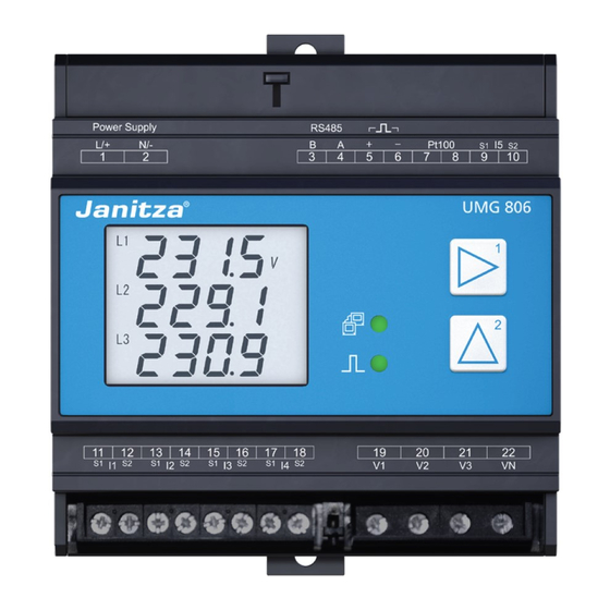
UMG 806 www.janitza.com Structure of the device Front panel and display Fig.: Front panel with display Fig.: Device front with screw terminal covers and display - 3D... - Page 23 UMG 806 Item Function/Designation Supply voltage connection Setup button RS-485 interface Digital output (active energy) Temperature measurement input (PT100) Residual current measurement input I5 Module locking LED (communication) Button 1 Module communication interface Button 2 LED (pulse activity) Module locking...
-
Page 24: Front View / Side View
UMG 806 www.janitza.com Front view / side view 90 mm (3.54 in) 63.5 mm (2.5 in) -
Page 25: Identification Of The Device (Rating Plate)
UMG 806 Identification of the device (rating plate) Item Designation Description Designation of origin Country of origin of the manufacturer. Operational data Supply voltage and maximum power consumption. Device type Device designation. DataMatrix code Coded manufacturer data. Part number Manufacturer’s part number. -
Page 26: Mounting
86) according to DIN EN 60715. The mounting orientation is arbitrary. Mounting orientation and attachment Proceed as follows to mount the UMG 806 on the mounting rail: 1. Push in the bottom bolt of the clamping mech- anism. -
Page 27: Grid Systems
UMG 806 Grid systems Suitable grid systems and maximum rated voltag- es according to DIN EN 61010-1/A1: Three-phase 4-conductor systems Three-phase 3-conductor systems with grounded neutral conductor with grounded phase : 230 V / 400 V 400 V Three-phase 4-conductor systems... -
Page 28: Installation
Janitza mea- surement device, the Janitza component and your system. AC/DC Ground- Voltage measurement ing of the system Auxiliary supply UMG 806 Fig. Schematic diagram, UMG 806 in a TN network... -
Page 29: Three-Phase 3-Conductor Network
Auxiliary supply UMG 806 Fig. Schematic diagram, UMG 806 in an IT network without N. 230/400V 50/60Hz Impedance AC/DC Ground- ing of the system Voltage measurement Auxiliary supply UMG 806 Fig. Schematic diagram, UMG 806 in an IT network with N. -
Page 30: Disconnect Switch
UMG 806 www.janitza.com Disconnect switch INFORMATION When installing in a building, provide a suitable The fuse is a line protection - it is not a device disconnect switch for the supply voltage in order protection! to disconnect your system and thus your device from the supply of power. -
Page 31: Voltage Measurement
UMG 806 Voltage measurement The device has 4 voltage measurement inputs and V ) and is suitable for various con- nection variants. WARNING Risk of injury or damage to the device due to electrical voltage and improper connection! Disregard of the conditions for the connections of the voltage and current measurement inputs may damage the device or cause serious injury or death. -
Page 32: Current Measurement
UMG 806 www.janitza.com Current measurement WARNING The device: Risk of injury due to high currents and high · Measures current exclusively via current trans- electrical voltages! formers. Severe bodily injury or death can result from: · Does not measure DC currents. -
Page 33: Measuring Variants
UMG 806 7.5.1 Measuring variants Three-phase 4-conductor system Three-phase 4-conductor system Current measurement via 3 current transformers Measurement via 3 current and 3 voltage transformers Three-phase 3-conductor system Three-phase 3-conductor system Current measurement via 2 current transformers Measurement via 2 current and 2 voltage transformers... -
Page 34: Summation Current Measurement
The meter is not an independent protective device against electric shock! INFORMATION Supply Consumer Suitable for recording residual currents > (k)S 100 mA in combination with Janitza residual (K)P current transformers. Fig. Example circuit diagram with ammeter in series connection... -
Page 35: Current Direction Of The Residual Current Transformers
UMG 806 7.6.2 Residual current transformer example 7.6.1 Current direction of the residual current transformers Operating equipment must have reinforced or double insulation from supply circuits! For residual current measurement with current transformers in AC operation at the measuring... -
Page 36: Connection Example - Residual Current Monitoring
UMG 806 www.janitza.com 7.6.3 Connection example - Residual current monitoring 11 12 13 14 15 16 17 18 UMG 806 Fig. Connection example, UMG 806 with residual current monitoring... -
Page 37: Temperature Measurement
UMG 806 Temperature measurement Example of temperature sensor: The UMG 806 has a temperature measurement A temperature sensor is to measure near uninsu- input. The temperature is measured via terminals 7 lated power lines in a 300 V CAT III network. -
Page 38: Rs-485 Interface
80 °C (176 °F)! Fig. Example: RS-485 interface of the UMG 806 (at the begin- ning of a bus topology) RS-485 bus Connection of additional devices Illustration example: RS-485 interface of the UMG 806 (in the middle of a bus topology) -
Page 39: Shielding
UMG 806 7.8.2 Termination resistors/Termination 7.8.1 Shielding For connections via the interfaces, use a twisted Terminate the beginning and end of your bus segments with termination resistors (120 Ω/0.25 W and shielded cable and observe the following for - see section "Bus structure (bus segment)”). The the shielding: ·... -
Page 40: Bus Structure (Bus Segment)
· Devices with bus termination switched on must be powered. Master Slave Slave Slave Repeater Slave Slave Slave Slave - Power supply necessary Master - e.g. UMG 605 - Bus terminator on Slave - e.g. UMG 806 Fig. Representation of a bus structure... -
Page 41: Digital Output
UMG 806 Digital output ATTENTION The device has 1 digital output, which Transmission error and material damage due to · Is electrically isolated from the evaluation elec- electrical malfunction. tronics via an optocoupler. With a cable length of more than 30 m, there is an ·... -
Page 42: Pc Connection
PC (with GridVis DHCP server automatically assigns IP address- ® software installed) are described below. es to the device and the PC. UMG 806 with 1. Connection via interface converter: PC with GridVis ® EC1 module PC with GridVis ®... -
Page 43: Operation And Button Functions
- see the section Password) takes you to the confi guration mode. · In confi guration mode, the character appears Fig. UMG 806 measuring display "Voltage L1-N, L2-N and L3-N" and function buttons. on the display. To switch back to the display mode: Function buttons ·... -
Page 44: Overview Of Measuring Display (Display Mode)
UMG 806 www.janitza.com Overview of measuring display (display mode) The measurement device measures electrical quantities such as voltage, current, power, power factor, frequency, energy, harmonics, asymmetries or extreme values. Some of these electrical quantities can only be read out via the communication interface. More detailed information can be found in the Modbus address list. -
Page 45: Examples Of Basic Measuring Displays
UMG 806 Examples of basic measuring displays Phase voltage Total active power U L1 = 200.0 V ∑P = 875 W U L2 = 100.0 V U L3 = 50.0 V Total reactive power Mains voltage ∑Q = 1515 var U L1-L2 = 264.4 V... -
Page 46: Examples Of Energy Measurement
UMG 806 www.janitza.com Examples of energy measurement Date and time are dis- played Active energy applied October 11, 2017, 13h EP = 30.784 kWh 28m 58s Active energy deliv- ered 9.10 Example of active EI1 module EP- = 50.430 kWh 1st analog input Id1 = 18.00 mA... -
Page 47: Configuration
UMG 806 10. Confi guration 10.1 Confi guration mode 10.2 Confi guration The confi guration mode is used to confi gure the · Press and hold buttons 1 and 2 simultaneously parameters necessary for the operation of the for 1 s to switch between the display and confi g- device. -
Page 48: Configuring The Current Transformer Ratios
10.2.2 Confi guring the current transformer Parameter address ratios Value of the The UMG 806 has 4 current measurement inputs primary current (I1 to I4) and one residual current measurement (100 A) input (I5). · The default setting of all current transformer ra- tios of the device (I1-I4 and I5) is 5 A / 5 A. -
Page 49: Example: Configuring The Current Transformer Ratios Of Residual Current Measurement Input I5 (700:1)
UMG 806 10.2.4 Example: Confi guring the current transformer ratios of residual current measurement input I5 (700:1) · Press and hold buttons 1 and 2 simultaneously for 1 s to switch between the display and confi g- uration modes. -
Page 50: Configuring The Voltage Transformer Ratios
10.2.5 Confi guring the voltage transformer Parameter address ratios Value of the The UMG 806 has 4 voltage measurement inputs primary voltage (V1 - V3 and VN). Of these, you can confi gure the (800 V) inputs L1 (V1) to L3 (V3). -
Page 51: Configuring The Rs-485 Interface (Modbus)
UMG 806 10.2.7 Configuring the RS-485 interface (Mod- 10.2.8 Configuring the Ethernet interface bus) INFORMATION To operate the device via the RS-485 interface (see chapter „7.8 RS-485 interface“ on page 38), The description of the Ethernet interface (mod- configure the following parameter addresses: ule 806-EC1) can be found in chapter „13.7.2... -
Page 52: Parameter List
UMG 806 www.janitza.com 10.3 Parameter list · Parameter addresses are not Modbus addresses! · Modbus addresses can be found in the separate Modbus address list in the download area at www.janitza.com Address Format Designation Setting range Unit Default setting uint32 Current transformer primary, I1..I3... - Page 53 UMG 806 Address Format Designation Setting range Unit Default setting uint16 DHCP mode 0 = fixed IP 1 = DHCP client uint8 IP address, xxx --- --- --- 0 .. 255 uint8 IP address, --- xxx --- --- 0 .. 255...
- Page 54 UMG 806 www.janitza.com Address Format Designation Setting range Unit Default setting uint16 Device password 0 .. 9999 0000 0 = No password configured uint16 Temperature offset value -99.9 .. 99.9 °C uint8 LCD backlight (on), time 0 .. 180 uint8 LCD start screen 0 ..
- Page 55 UMG 806...
-
Page 56: Commissioning
UMG 806 www.janitza.com 11. Commissioning INFORMATION WARNING Risk of injury due to electrical voltage! Before commissioning, delete any production-relat- ed contents of the energy meters (see section „10.3 If the device is exposed to surge voltages above Parameter list“ on page 52). -
Page 57: Measured Current
UMG 806 11.4 Measured current 11.7 Checking measurement The device: Correctly connected voltage and current measure- · Measures current exclusively via current trans- ment inputs result in correctly calculated and dis- formers. played individual and summation power readings. · Is designed for the connection of current trans- formers with secondary currents of ../1 A and ../5... -
Page 58: Connection Example, Umg 806
UMG 806 www.janitza.com 12. Connection example, UMG 806 PT100 RS232 RS485 PT100 AI1+ AI2+ AI3+ AI4+ AIC Power supply RS485 Energy pulse Temperature Analog inputs UMG 806 Module 806-EI1 Relais outputs Current measurement Voltage measurement 11 12 15 16 17 18... -
Page 59: Expansion Modules
UMG 806 13. Expansion modules The following optional expansion modules can be used to extend the functionality of the basic device (the basic device only supports one extension module per module type): · 806-EC1 module · 806-ED1 module · 806-EI1 module Use the parameter list to activate the respective module, see chapters „10.3 Parameter list“... - Page 60 Disregard of the installation instructions can dam- · The UMG 806 as a basic device allows the age or destroy your device. installation of one module type each (maximum · Provide adequate air circulation in your installa- 1 x EC1, 1 x ED1, 1 x EI1).
-
Page 61: Installing The Modules
3. Plug in the module (the plug is recessed on the side of the UMG, the socket is on the module). 6. The UMG 806 can be combined with one 806-EC1, 806-EI1 or 806-ED1. 4. Check the connection of the UMG to the mod-... -
Page 62: Front / Side Views
UMG 806 www.janitza.com 13.3 Front / side views 13.3.1 806-EC1 module 13.3.2 806-ED1 module... -
Page 63: 806-Ei1 Module
13.4.1 806-ED1 module 13.4.2 806-EI1 module INFORMATION Observe the specified wiring when connecting the digital inputs! The high level is achieved by short-cir- cuiting with PIN 5 (DIC). The wiring is therefore different from the other devices of the Janitza UMG series. -
Page 64: Module Detection
Id1 = 18.00 mA Hardware and software preparation: 1. Prepare the 806-EC1 module and the UMG 806 measurement device. 2. Plug the 806-EC1 module onto the UMG 806 Relay output status measurement device. Switch on the measure- "12" means 2 relay ment device. -
Page 65: Configuring The Ethernet Interface
· Modbus addresses can be found in the separate DHCP mode Modbus address list. · Use DHCP to configure your UMG 806 with the 806-EC1 module for incorporation into an exist- ing network. ATTENTION · Depending on the configuration of the DHCP... -
Page 66: Relay Outputs Of Modules Ed1
410 = 1), configure the following parameters in the configuration mode: • Alarm element (412) Fig. Connection example: UMG 806 with 806-EC1 module and PC require a fixed IP address (parameter 205 = 0). • Alarm value (413) •... -
Page 67: Manual Control Via Modbus Addresses
(active or inactive, the time period set is not relevant in level mode) until a control signal via the Modbus addresses changes this status. (See also Modbus address list, UMG 806 at www.janitza.com) - Page 68 UMG 806 www.janitza.com 13.8.3 Table "Parameters of the alarm ele- F - Limit value exceeded ments" - addresses (412, 422, 432, 442) F - Limit value undershot U unb - Limit value exceeded Contents of parameter address (alarm elements) U unb - Limit value undershot...
-
Page 69: Alarm Elements And Units Of The Alarm Limit Values
UMG 806 13.8.4 Alarm elements and units of the alarm limit values Unit of the rele- Alarm element (designation/formula variable) vant alarm value Ua (V1), Ub (V2), Uc (V3), Un (Vn), Uab (V12), Ubc (V23), Uca (V31), Ul (VI - any mains voltage) Voltage 0.1 V... -
Page 70: Ec1 Module Homepage
14. EC1 module homepage 14.1 LOG IN 14.2 Overview The device’s own UMG 806 module homepage The homepage consists of four main parts: can be accessed via the EC1 module by calling up the IP address in a web browser. · Home... - Page 71 UMG 806 Home: Start page with a brief overview of the most important measured values Measured values: Complete overview of all relevant measured values Settings Drop-down menu providing access to all setting options Information: Displays basic device information Time / Date: Displays the time and date (GMT)
-
Page 72: Home
· Active power in kilowatts · Cos-phi (unitless) · Vectorial sum value (L1..L3) of the active power and cos-phi Fig. Homepage of the UMG 806 with EC1 module 14.4 Measured value display In the menu bar, select "Measured values" to dis- play a complete overview of the device’s relevant... - Page 73 UMG 806 Basic parameters, phase-referenced (L1, L2, L3) Voltage in volts (LL reference) (V) Voltage in volts (LN reference) (V) Active power in kilowatts (kW) Consumed active energy in kilowatt hours (kWh) Reactive power in kilovar (kvar) Reactive energy in kilovarh (kvarh)
- Page 74 UMG 806 www.janitza.com Fig. Measured value displays ED1, EI1 ED1 module - Digital inputs and relay outputs · Display of the momentary value and the meter readings of all digital inputs (1-4) · Display of the present state of all relay outputs (1 and 2) EI1 module - Analog inputs and relay outputs ·...
-
Page 75: Settings
· Firmware Update: Update of the firmware for the UMG 806 and EC1 module 14.5.1 TCP/IP · Configuration of all TCP/IP network settings for the communication between the UMG 806 basic device and the EC1 module. · DHCP is the default setting when the device is delivered. -
Page 76: Modbus
EC1 must match the corresponding device address of the UMG 806 whose values are to be displayed on the homepage. · All changes must be saved with "Save" for them to take effect. Fig. Example of Modbus settings for the UMG 806 device... -
Page 77: Current Transformer (Ct) / Voltage Transformer (Vt) Ratios
UMG 806 14.5.3 Current transformer (CT) / Voltage transformer (VT) ratios Configuration of all transformer ratios · Configuration options: - VT-1 (L1-L3): Entry for primary side voltage transformers L1-L3 (range 1 to 999999) - VT-2 (L1-L3): Entry for secondary side voltage... -
Page 78: Password
UMG 806 www.janitza.com 14.5.4 Password Enter and/or change password to access device settings and homepage. · Default: admin / admin · Current password: Enter the current password. · New password: Enter the new, user-defined password with a maximum of 20 characters. -
Page 79: Firmware Update
UMG 806 14.5.5 Firmware Update This function can be used to update the firmware of the UMG 806 basic device as well as the EC1 communication module. · Select device: Selection of the device to be updated. · Select file: 1. -
Page 80: General Information
- Can be set via GridVis - Can contain user-defi ned additional information about the device (40 characters; ASCII 256) · Basic device fi rmware version (UMG 806): Currently installed fi rmware version · Communication module fi rmware version (EC1): Currently installed fi rmware version ·... - Page 81 UMG 806...
-
Page 82: Service And Maintenance
UMG 806 www.janitza.com 15. Service and maintenance 15.2 Front panel foil and display Prior to outbound delivery, the device is subjected to various safety tests and is marked with a seal. Please note the following for the care and cleaning... -
Page 83: Clock/Battery
UMG 806 15.5 Clock/Battery WARNING The supply voltage supplies the internal clock of Risk of injury due to electrical voltage! Serious the meter. If the supply voltage fails, the battery personal injury or death may occur due to: takes over the supply of voltage to the clock. The ·... -
Page 84: Procedure In The Event Of A Malfunction
UMG 806 www.janitza.com 15.6 Procedure in the event of a malfunction Failure mode Cause Remedy External fuse for the supply voltage has No display Replace fuse. tripped. No measured voltage connected. Connect measured voltage. No current display. No measured current connected. - Page 85 UMG 806...
-
Page 86: Technical Data
UMG 806 www.janitza.com 16. Technical data 16.1 Technical data, UMG 806 General Net weight 300 g (0.66 lb) Approx. B = 90 mm (3.54 in), H = 90 mm (3.54 in), Device dimensions D = 63.5 mm (2.5 in) Battery... - Page 87 UMG 806 Voltage measurement 3-phase 4-conductor systems with rated voltages up to 230 V LN / 400 V LL (+/-10%) acc. to IEC 3-phase 3-conductor systems (grounded) with rated voltages up to 400 V LL (+/-10%) acc. to IEC...
- Page 88 UMG 806 www.janitza.com Digital outputs Energy pulse output Switching voltage max. 35 V DC Switching current max. 10 mA eff DC Response time approx. 500 ms Pulse width 80 ms ±20% Digital output (energy pulses) max. 10 Hz Temperature measurement...
- Page 89 UMG 806 Connecting capacity of the terminals (voltage measurement) Connectible conductors. Only connect one conductor per terminal point! Single core, multi-core, fine-stranded 0.2 - 4 mm , AWG 24-12 Wire ferrules (insulated/non-insulated) 0.25 - 2.5 mm , AWG 23-14 Strip length 7 mm (0.2756 in)
-
Page 90: Performance Characteristics Of Functions
UMG 806 www.janitza.com 16.2 Performance characteristics of functions Function Symbol Accuracy class Display range Norm IEC61557-12 Voltage 0-999.9 kV IEC61557-12 Current 0-99,99 kA IEC61557-12 Active power 0-9999 MW IEC61557-12 Reactive power 0-9999 Mvar IEC61557-12 Apparent power 0-9999 MVA IEC61557-12 Power factor 0-1.000... -
Page 91: Technical Data Of The Modules
UMG 806 16.3 Technical data of the modules General 806-EC1 806-EI1 806-ED1 approx. 82 g approx. 91 g approx. 82 g Net weight (0.18 lbs) (0.20 lbs) (0.18 lbs) Approx. B = 36 mm (1.42 in), H = 90 mm (3.54 in), Device dimensions D = 63.5 mm (2.5 in) - Page 92 Janitza electronics GmbH Vor dem Polstück 6 35633 Lahnau, Germany Support tel. +49 6441 9642-22 Email: info@janitza.com info@janitza.com | www.janitza.com Subject to technical changes. The current version of the document can be found in the download area at www.janitza.com...
Need help?
Do you have a question about the UMG 806 and is the answer not in the manual?
Questions and answers