Table of Contents
Advertisement
Janitza electronics GmbH
Vor dem Polstück 1
D-35633 Lahnau
Support tel. 0049 6441 9642-22
Fax 0049 6441 9642-30
E-mail: info@janitza.com
Internet: http://www.janitza.com
Power Analyser
Expansion UMG 96RM-P
Expansion UMG 96RM-CBM
Supplementary description for the basic device for
expansions -P and -CBM
UMG 96RM-P
UMG 96RM-CBM
Advertisement
Table of Contents

Subscribe to Our Youtube Channel
Related Manuals for janitza UMG 96RM-P


Summary of Contents for janitza UMG 96RM-P
- Page 1 Power Analyser Expansion UMG 96RM-P Expansion UMG 96RM-CBM Supplementary description for the basic device for expansions -P and -CBM Janitza electronics GmbH UMG 96RM-CBM UMG 96RM-P Vor dem Polstück 1 D-35633 Lahnau Support tel. 0049 6441 9642-22 Fax 0049 6441 9642-30 E-mail: info@janitza.com...
-
Page 2: Table Of Contents
UMG 96RM-P/-CBM Table of contents General Service and maintenance Incoming inspection Battery Expanded scope of delivery UMG 96RM-P Battery monitoring function or -CBM Replacing the battery Available accessories Firmware update Product description Device calibration Proper use Calibration intervals Expanded features of the UMG 96RM... -
Page 3: General
EMAIL at: info@janitza.de or in part, photocopied, reprinted, or reproduced by mechanical or electronic means, or in any other manner... - Page 4 UMG 96RM-P/-CBM Instructions for use Please read the operating manual included in the delivery This device is to be operated and maintained exclusively as well as all other publications that must be drawn by specialized personnel. from for working with this product (in particular for Specialized personnel are persons, that based on their the installation, operation or maintenance).
- Page 5 UMG 96RM-P/-CBM Concerning these operating instructions This description of the device expansion is only valid in conjunction with the operating instructions for the basic device. Please note the following points: • Before using the device read the operating instructions and this description.
-
Page 6: Incoming Inspection
UMG 96RM-P/-CBM Incoming inspection The prerequisites of faultless, safe operation of this device are proper transport and proper storage, setup and assembly, as well as careful operation and maintenance. If it can be assumed that risk-free operation is no longer possible, the unit must be immediately put out of operation and secured against being put back into operation again. -
Page 7: Expanded Scope Of Delivery Umg 96Rm-P Or -Cbm
UMG 96RM-P/-CBM Expanded scope of delivery UMG 96RM-P or -CBM Number Item no. CBM- Designation Expansion Expansion 52.22.xxx* UMG 96RM-P or UMG 96RM-CBM* 29.01.036 Fixing clamps 33.03.142 Operating instructions "Expansion UMG 96RM“. 10.01.835 Screw terminal, pluggable, 2-pole (current measurement I4) 10.01.833... -
Page 8: Product Description
UMG 96RM-P/-CBM Product description Proper use Device characteristics The UMG 96RM is intended for the measurement and • Supply voltage: 230V (95V-240V AC) calculation of electrical parameters such as voltage, • Frequency range: 45-65Hz current, power, energy, harmonics etc. in building installations, on distribution units, circuit breakers and busbar trunking systems. -
Page 9: Expanded Features Of The Umg 96Rm Variants P And Cbm
• Additional 4th current measurement input for current transformer • RS485 interface (Modbus RTU, slave, up to 115 kbps) • USB interface • Only UMG 96RM-P variant: Profibus interface (Profibus DP V0) • Additional 4 digital outputs • 4 digital inputs • Working temperature range -10°C .. -
Page 10: Measuring Process
UMG 96RM-P/-CBM Measuring process Parameterising The UMG 96RM measures continuously and calculates all You can parameterise the UMG via buttons 1 and 2 or effective values over a 9 period interval. The UMG 96RM via the RS485 or USB interface. - Page 11 UMG 96RM-P/-CBM...
-
Page 12: Gridvis Network Analysis Software
RS485 UMG 96RM The UMG 96RM can be programmed and read out Connecting a UMG 96RM-P or -CBM to a PC via the USB using the GridVis network analysis software included interface: in the scope of deliverables. A PC must be connected via a serial interface to the USB or RS485 interface of the UMG 96RM for this (see connection variants). -
Page 13: Use Of The Device
UMG 96RM-P/-CBM UMG 96RM RS485 Use of the device Connecting a UMG 96RM-P or -CBM via a UMG 604 as gateway: Information regarding the installation with the basic installation, operation, configuration and commissioning of the device is provided in the respective chapter in... -
Page 14: Led Status Bar
- independent of whether there is a connection on the interface. Profibus (only -P model) Profibus (only UMG 96RM-P variant) Fig. LED status bar for inputs and outputs The LED associated with the Profibus provides... - Page 15 UMG 96RM-P/-CBM Profibus status LED Flashing frequency Green Status Illuminates steadily Still no contact with PLC Slowly (approx. 1x per sec.) Fault in the configuration data Very slowly (approx. 1x per 2 sec.) Fault with data exchange Illuminates steadily Data exchange with the PLC Quickly (approx.
-
Page 16: Current Transformer Input I4
Direct measurement without a current transformer is not possible with the UMG 96RM-P/-CBM. Only AC currents can be measured - DC currents cannot. In doing so, with a voltage only an apparent current measurement is possible due to the multiplier being missing. - Page 17 UMG 96RM-P/-CBM Direct measurement Open-circuit current transformers! Direct measurement of the nominal High voltage spikes that are dangerous to current without a current transformer is touch can occur on current transformers not possible with the UMG 96RM that are driven with open-circuit secondary windings! With "safe open-circuit current...
-
Page 18: Usb Interface
UMG 96RM-P/-CBM USB interface The Universal Serial Bus (USB) enables a rapid and uncomplicated connection between the device and a computer. After the installation of the USB driver the device data can be read out via the GridVis software and firmware updates can be installed. - Page 19 UMG 96RM-P/-CBM...
-
Page 20: Installation Of Usb Driver
UMG 96RM-P/-CBM Installation of USB driver With internet access or authorisation for automatic With missing internet access or missing authorisation for updates of the driver library: automatic updates of the driver library or with Windows XP SP2: With all current operating systems (e.g. Windows 7) the required drivers are automatically installed the first • Windows system:... - Page 21 UMG 96RM-P/-CBM Checking the USB installation • Open the Devices and printers window in Windows 7 via the control panel, for example. • Open the Properties of the device FT232 USB UART by double-clicking. Further information about the device can be found in the General and Hardware tabs.
-
Page 22: Digital Outputs
UMG 96RM-P/-CBM Digital outputs The UMG 96RM-P and UMG 96RM-CBM have 6 digital outputs, whereby these are split into two groups of 2 and 4 outputs (see illustration on the right). Group 2 Further information on the digital outputs and the... -
Page 23: Dc Connection Example
UMG 96RM-P/-CBM DC connection example External UMG 96RM-P/-CBM auxiliary voltage 24V DC Digital Ouput 1 Digital Ouput 2 Digital Ouput 3 Digital Ouput 4 Digital Ouput 5 Fig. Example for two relays connected to Digital Ouput 6 the digital outputs... -
Page 24: Digital Inputs
UMG 96RM-P/-CBM Digital inputs External auxiliary voltage 24V DC The UMG 96RM-P and UMG96RM-CBM have 4 digital inputs, each of which can have a signal transducer UMG 96RM-P/-CBM connected. Digital inputs 1-4 On a digital input an input signal is detected if a voltage... - Page 25 UMG 96RM-P/-CBM S0 pulse input External auxiliary voltage 24V DC You can connect an S0 pulse transducer per DIN EN62053-31 to any digital input. UMG 96RM-P/-CBM Digital inputs 1-4 This requires an auxiliary voltage with an output voltage in the range 20 .. 28V DC and a resistor of 1.5kOhm.
-
Page 26: Profibus Interface (Only Umg 96Rm-P)
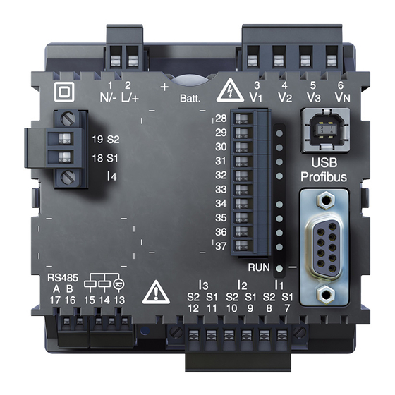
UNG 96RM-P via a Profibus connector. For the connection we recommend a 9-pin Profibus connector, e.g. type "SUBCON-Plus-ProfiB/AX/SC" from Phoenix, item number 2744380. (Janitza item no:13.10.539) D-sub receptacle for Profibus Fig. UMG 96RM-P with D-sub receptacle for Profibus (View on rear). - Page 27 UMG 96RM-P/-CBM Connection of the bus wiring The inbound bus wiring is connected to terminals 1A and 1B of the Profibus connector. The continuing bus wiring for the next device in line should be connected to terminals 2A and 2B.
- Page 28 UMG 96RM-P/-CBM Screening Twisted screened cable should be used for connections Transfer speeds Max. via the RS485 interface. in Kbit/s segment length 9.6; 19.2; 45.45; 93.75 1200m • Earth the screens of all cables that lead to 187.5 1000m the cabinet, upon entering the cabinet.
- Page 29 UMG 96RM-P/-CBM Bus structure • All devices are connected in a bus structure (line) and • It is recommended that the master be placed at each device has its own address within the bus (see the end of a segment.
- Page 30 PLC. and four factory pre-configured Profibus profiles. The device master file for the UMG 96RM-P has the filename "96RM0D44.GSD" and is included on the data A Profibus profile can: carrier as part of the scope of deliverables.
- Page 31 • • PLC process input box Profile number Measurement values 1. Byte = Return signal from the profile number 2. Byte = Requested by UMG 96RM-P Data • • Fig. Block diagram for data exchange between PLC and UMG 96RM-P.
- Page 32 UMG 96RM-P/-CBM Factory pre-configured profiles Profibus profile number 8 Profibus profile number 9 Byte Value type Value Scaling Byte Value type Value Scaling index format index format Effective voltage L1 Float Effective energy sum L1..L3 Float Effective voltage L2 Float Effective energy sum L1..L3 drawn...
- Page 33 UMG 96RM-P/-CBM Profibus profile number 10 Profibus profile number 11 Byte Value type Value Scaling Byte Value type Value Scaling index format index format Effective power L1 Float Effective voltage L1 Integer Effective power L2 Float Effective voltage L2 Integer...
-
Page 34: Service And Maintenance
UMG 96RM-P/-CBM Service and maintenance Battery The internal clock is fed from the supply voltage. If The device is subjected to several different safety the supply voltage fails then the clock is powered tests before leaving the factory and is labelled with a by the battery. -
Page 35: Battery Monitoring Function
UMG 96RM-P/-CBM Battery monitoring function Status Status description • Battery capacity is <85% The device indicates the condition of the battery via • Operator confirmation required the symbol "EEE" followed by "bAt" and the status • Message appears weekly after confirmation number. -
Page 36: Replacing The Battery
UMG 96RM-P/-CBM Replacing the battery If the battery capacity is shown as < 75 %, we recom- mend that the battery be replaced. Procedure 1. Disconnect system and device from power supply before beginning work. 2. Discharge any electrostatic charge in your body, e.g. -
Page 37: Firmware Update
UMG 96RM-P/-CBM Firmware update Device calibration If the device is connected to a computer via the RS485 or The devices are calibrated by the manufacturer at USB interface then the device firmware can be updated the factory - it is not necessary to recalibrate the device via the GridVis software. -
Page 38: Procedure In The Event Of Faults
UMG 96RM-P/-CBM Procedure in the event of faults Possible fault Cause Remedy No display See instructions for basic device No current display See instructions for basic device Current displayed is too large or See instructions for basic device too small. - Page 39 UMG 96RM-P/-CBM Possible fault Cause Remedy No connection via USB Driver fault Disconnect USB interface briefly Use another USB port Reinstall driver Device still does not work Device defective. Send the device to the despite the above measures. manufacturer for inspection and testing along with an accurate fault description.
-
Page 40: Technical Data For The Expansions
UMG 96RM-P/-CBM Technical data for the expansions General Net weight Approx. 185g Device dimensions Approx. w = 96mm, h = 96mm, d = 78mm Service life of background lighting 40000h (50% of initial brightness) Battery 3V, TYP CR2032 (according to UL1642) - Page 41 UMG 96RM-P/-CBM Cable lengths (digital inputs and outputs) Up to 30m Unscreened More than 30m Screened Connection characteristics of the terminals (digital inputs and outputs) Rigid/flexible 0.14 - 1.5mm , AWG 28-16 Flexible with core end sheath without plastic sleeve 0.25 - 1.5mm...
- Page 42 UMG 96RM-P/-CBM Current measuring I4 Measurement range 0 .. 5A (max. overload 7 A Crest factor 1,98 Resolution 0.1mA (Display 0.01A) Accuracy class 1 (IEC61557-12) Overvoltage category 300V CAT II Measurement surge voltage Power consumption Approx. 0.2 VA (Ri=5mOhm) Overload for 1 sec.
- Page 43 UMG 96RM-P/-CBM Serial interfaces (in addition to basic device) Profibus (only UMG 96RM-P) - Profibus DP/V0 9.6kbps to 12Mbps - Receptacle D-sub, 9-pole - Receptacle Type B Device variants RS485 Profibus Digital Digital Inputs Outputs Input Basic device UMG 96RM...
- Page 44 UMG 96RM-P/-CBM Dimension diagrams Cut-out size: 92 x 92 +0,8 +0,8 Rear view of UMG 96RM-P Side view of UMG 96RM-P with USB and Profibus connectors inserted ca. 108 (depth without connector) All dimensions in mm...
- Page 45 UMG 96RM-P/-CBM Rear view of UMG 96RM-CBM Side view of UMG 96RM-CBM with USB connector inserted ca. 108 (depth without connector) All dimensions in mm...
-
Page 46: Declaration Of Conformity
UMG 96RM-P/-CBM Declaration of conformity The UMG 96RM-P/-CBM fulfils the following protection requirements: Directive 2004/108/EC in conjunction with DIN EN61326-1:2006-10 (IEC 61326-1) as well as the Directive 2006/95/EC in conjunction with DIN EN 61010-1:2002-08 (IEC 61010-1) Standards taken into consideration:... - Page 47 UMG 96RM-P/-CBM...
-
Page 48: Connection Example
UMG 96RM-P/-CBM Connection example 28 29 Digital outputs Digital inputs RS485 UMG 96RM-P/CBM Auxiliary voltage Measuring voltage Measuring currrent 18 19 230V/400V 50Hz...
Need help?
Do you have a question about the UMG 96RM-P and is the answer not in the manual?
Questions and answers