
Related Manuals for janitza UMG 801


Summary of Contents for janitza UMG 801
- Page 1 Modular Power Analyzer UMG 801 User manual and technical specifications Janitza electronics GmbH Vor dem Polstück 6 D-35633 Lahnau Support tel. +49 6441 9642-22 Fax +49 6441 9642-30 Email: info@janitza.de www.janitza.de...
- Page 2 UMG 801 www.janitza.de UMG 801 Modular multifunctional meter for recording energy quantities Doc. no.: 2.053.021.0b Date: 12/2019 The German version is the original edition of the documentation...
- Page 3 Nonetheless, we wish to point out that updates of this document are not always possible at the same time as technical refinements are implemented in our products. Please see our website under www.janitza.de for the current version. Please see our website under www.janitza.de for the current version.
-
Page 4: Table Of Contents
UMG 801 www.janitza.de TABLE OF CONTENTS 1. Information on the device and the user manual 1. 1 Disclaimer 1. 2 Copyright notice 1. 3 Technical changes 1. 4 About this user manual 1. 5 Defective device/disposal 2. Safety 2. 1 Display of warning notices and safety information 2. - Page 5 UMG 801 4. Structure of the device 4. 1 Front panel and display 4. 2 Side views 4. 3 Bottom view 4. 4 Identification of the device (rating plate) 5. Mounting 5. 1 Installation location 5. 2 Mounting orientation and attachment 6.
- Page 6 UMG 801 www.janitza.de 8. PC connection 8. 1 Connection to a PC 9. Peripherals 9. 1 Ethernet interface 9. 2 Daisy chain connection 9. 3 RS-485 interface (serial interface) 9. 3. 1 Shielding 9. 3. 2 Termination resistors/Termination 9. 3. 3 Bus structure (bus segment) 9.
- Page 7 UMG 801 11. 7 Configuring the system 11. 7. 1 PIN 11. 7. 2 Brightness 11. 7. 3 Time 11. 7. 4 Date 11. 8 Reset 11. 8. 1 Standard factory settings 11. 8. 2 Restart 11. 8. 3 Reset minimum, maximum and average values 12.
- Page 8 UMG 801 www.janitza.de 17. Service and maintenance 17. 1 Repair and calibration 17. 2 Front panel foil and display 17. 3 Service 17. 4 Device adjustment 17. 5 Firmware update 17. 6 Clock/Battery 17. 7 Battery replacement 18. Error messages 18.
- Page 9 UMG 801...
-
Page 10: Information On The Device And The User Manual
Technical changes · Make sure that your device matches the user manual. · This user manual applies to the UMG 801. Separate validities and distinctions are marked. · First read and understand the documents associated with the product. · Keep the documents associated with the product available for the entire service life and pass them on to any possible subsequent users. -
Page 11: Defective Device/Disposal
· When doing so, please bear the terms for transportation in mind. INFORMATION Please return defective or damaged devices to Janitza electronics GmbH in accordance with the shipping instructions for air or road freight (complete with accessories). Observe special regulations for devices with built-in... -
Page 12: Safety
UMG 801 www.janitza.de Safety Hazard levels The chapter on Safety contains information which must be observed to ensure your personal safety Warning and safety information is marked by a and avoid material damage. warning symbol, and the hazard levels are shown... -
Page 13: Product Safety
UMG 801 Product safety WARNING The device reflects current engineering practice Risk of injury due to electrical voltage! and accepted safety standards, but hazards can Severe bodily injury or death can result! Therefore arise nonetheless. please abide by the following: ·... -
Page 14: Electrically Qualified Personnel
UMG 801 www.janitza.de Electrically qualified personnel Safety information for handling current transformers and measurement devic- To avoid bodily injury and material damage, only es with residual current measurement electrically qualified personnel are permitted to work on the devices and their components,... -
Page 15: Handling Batteries/Accumulators
The battery used in the device may cause fire or burns if used improperly. · Only replace the battery with the same type or types recommended by Janitza! · Observe the polarity when installing the battery! · Remove batteries only with non-conductive tools (e.g. -
Page 16: Product Description
UMG 801 www.janitza.de Product description Device description CAUTION The device is a multifunctional network analyzer Malfunction and damage of the device or risk of and is suitable for: injury due to improper connection. · Measurements and calculations of electrical Improperly connected devices can deliver incorrect... -
Page 17: Intended Use
UMG 801 Intended use The device is: · Intended for installation in control cabinets and small installation distributors. · Not intended for installation in vehicles! Use of the device in non-stationary equipment constitutes an exceptional environmental condition and is only permissible by special agreement. -
Page 18: Performance Characteristics
Performance characteristics EU conformity declaration Please see the EU declaration of conformity General posted at www.janitza.de for the laws, standards · DIN rail measurement device with the dimensions and directives applied by Janitza electronics 144 x 90 x 76 mm. -
Page 19: Scope Of Delivery
· All supplied options and design variants are 52.31.001 UMG 801 (basic device) described on the delivery note. 52.31.205 Bus connector for module connec- tion to the UMG 801 (basic device) 33.03.376 Installation instructions DE/EN 33.03.342 Supplement "Safety Information" 10.01.953 End angle 08.01.505 Patch cable... -
Page 20: Measuring Method
® With the GridVis network analysis software ® available at www.janitza.de, you can configure your measurement device and read out data for analysis. To do so, connect a PC to your measurement device via the Ethernet interface. Performance characteristics of the GridVis ®... -
Page 21: Overview Of The Range Of Functions
UMG 801 3.11 Overview of the range of functions 3.11.2 Communication 3.11.1 Configuration on the device (via 6 but- · One RS-485 interface for communication with tons) Modbus/RTU devices. · Firmware update via Ethernet. · Password protection (can only be configured on ·... -
Page 22: Measured Values (With Current Component)
UMG 801 www.janitza.de 3.11.4 Measured values (with current component) Device/system Channel Min. Max. Average Measured values related related value value value (with current component) ü ü Effective current I ü ü Real part Current Re{I} ü ü Imaginary part Current Im{I} ü... - Page 23 UMG 801 Device/system Channel Min. Max. Average Measured values related related value value value (with current component) Energy (3 tariffs, consisting of 1 main tariff and 2 ancillary tariffs) Active energy W 3 x 3 tariffs System total Active energy W...
-
Page 24: Structure Of The Device
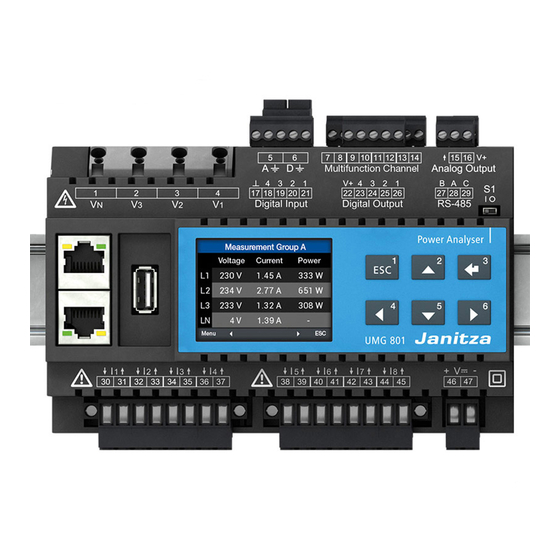
UMG 801 www.janitza.de Structure of the device Front panel and display Lower terminal row Upper terminal row Fig.: Front panel with display Fig: Front panel with display - 3D... - Page 25 UMG 801 Item Function/Designation Supply voltage connection Current measurement inputs I5 to I8 for · Measurement of an additional system (L1, L2, L3, N) · Single channel measurements Current measurement inputs I1 to I4 for · Measurement of one system (L1, L2, L3, N) ·...
-
Page 26: Side Views
UMG 801 www.janitza.de Side views Bottom view Floor bolts JanBus interface (bus connector connection, module connection) Floor bolts INFORMATION When the device is delivered, the bus connectors are already plugged into the JanBus interface! -
Page 27: Identification Of The Device (Rating Plate)
01B • 1 UMG 801 5231001 XXXX/0001 Aux: 24-48V • 4W MAC: 00:0e:6b:03:00:00 Made in Germany • www.janitza.com Item Designation Description MAC address Unique identification of the device in a computer network. Operational data Supply voltage and maximum power consumption. -
Page 28: Mounting
Sockets for the insertion of a module Fig.: Bus connector of the UMG 801 (scope of delivery) INFORMATION Fig. Underside of device with bus connector installed and floor When the device is delivered, the bus connectors bolt pressed in. - Page 29 UMG 801 3. Press your meter with the bus connector onto The UMG 801 is suitable for connecting up to 10 the mounting rail frontally until the 4 floor bolts modules via the bus connector (JanBus interface). engage. Position of the bus...
-
Page 30: Grid Systems
UMG 801 www.janitza.de Grid systems Suitable grid systems and maximum rated voltag- es according to DIN EN 61010-1/A1: Three-phase 4-conductor systems Three-phase three-conductor systems with grounded neutral conductor with grounded phase : 480 V / 830 V 830 V Range of application of the meter: ·... - Page 31 UMG 801...
-
Page 32: Installation
UMG 801 www.janitza.de Installation Use the meter for voltage measurement in TN, TT 230V/400V 50/60Hz and IT networks with the approved overvoltage 230 VAC category of 1000 V CAT III according to IEC and 600 V CAT III according to UL (rated surge voltage 8 kV). -
Page 33: Supply Voltage
UMG 801 Supply voltage ATTENTION Material damage due to disregard of the WARNING connection instructions! Risk of injury due to electrical voltage! Disregard of the connection instructions or Severe bodily injury or death can result from: exceeding the permissible voltage range can ·... -
Page 34: Voltage Measurement
UMG 801 www.janitza.de Voltage measurement INFORMATION The device has 4 voltage measurement inputs and As an alternative to the fuse and isolation device, is suitable for various connection variants. you can use a line circuit breaker. WARNING INFORMATION Risk of injury or damage to the device due to... -
Page 35: Overvoltage
UMG 801 7.4.1 Overvoltage INFORMATION The voltage measurement inputs are designed The device only determines measured values if a for measurements in low-voltage networks in voltage L1-N of greater than 10 V (4-conductor which nominal voltages occur as described in the measurement) or a voltage L1-L2 of greater than 18 chapter „19. -
Page 36: Connection Variants For Voltage Measurement
UMG 801 www.janitza.de 7.4.3 Connection variants for voltage measurement Three-phase 4-conductor system Three-phase three-conductor system Three-phase four-conductor system without voltage Three-phase three-conductor system with voltage transformer transformer Three-phase 4-conductor system Three-phase three-conductor system Three-phase four-conductor system with voltage Three-phase three-conductor system (asymmetrical load) -
Page 37: Current Measurement
UMG 801 Current measurement WARNING The device: Risk of injury due to high currents and high · Measures current exclusively via current electrical voltages! transformers. Severe bodily injury or death can result from: · Permits the connection of current transformers ·... -
Page 38: Connection Variants For Current Measurement
UMG 801 www.janitza.de 7.5.1 Connection variants for current measurement Current measurement I1 to I4 and I5 to I8 Three-phase 4-conductor system Three-phase three-conductor system 33 34 Current measurement via 3 current transformers Current measurement via 2 current transformers (Aron circuit) -
Page 39: Summation Current Measurement
UMG 801 7.5.2 Summation current measurement 7.5.3 Ammeter For a summation current measurement via two For a current measurement with an additional current transformers, first set their total ratio on ammeter, connect the ammeter in series to the the device (for setting the current transformer UMG: ratios, see section „11.4 Configuring current... -
Page 40: Multifunction Channels
UMG 801 www.janitza.de Multifunction channels Residual current measurement (RCM) The terminal pairs 7/8, 9/10, 11/12 and 13/14 The measurement device is suitable as a residual optionally serve as connections (4 channels) for the current monitoring device (RCM) for monitoring following measurements: alternating currents, pulsating direct currents and 1. -
Page 41: Current Direction Of The Residual Current Transformers
UMG 801 7.7.1 Current direction of the residual current ATTENTION transformers Faulty cross currents, incorrect measurements, For residual current measurement with current and even damage to the device and/or your transformers in AC operation at the measuring system due to lack of galvanic isolation! -
Page 42: Residual Current Transformer Example
UMG 801 www.janitza.de 7.7.2 Residual current transformer example Operating equipment must have reinforced or double insulation from supply circuits! Example: A residual current transformer is used to measure on insulated mains wiring in a 300 V CAT III network. Solution:... -
Page 43: Connection Examples - Residual Current Measurement
UMG 801 7.7.4 Connection examples - Residual cur- CAUTION rent measurement e.g.: e.g.: Risk of injury or damage to the meter/your Residual current Residual current system due to short circuit! transformer CT-AC-RCM transformer Inadequate insulation of the operating equipment... -
Page 44: Connection Example - Residual Current Monitoring
N V3 V2 30 31 32 33 34 35 36 37 UMG 801 Fig. Connection example UMG 801 with residual current monitoring via 2 multifunction channels (7/8, 9/10) as measuring inputs for the residual currents. CAUTION Risk of injury or damage to the meter/your... -
Page 45: Temperature Measurement
UMG 801 Temperature measurement Example of temperature sensor: A temperature sensor is to measure near As already described in section "7.6 Residual uninsulated power lines in a 300 V CAT III network. current measurement (RCM)" on page 40, the terminal pairs 7/8, 9/10, 11/12 and 13/14... -
Page 46: Pc Connection
Client Consult your network administrator for the correct network settings for your device. Ethernet RS-485 - Modbus Ethernet e.g. UMG 801 UMG 96-S2 UMG 103 as gateway Slave 1 Slave 2 (master device) 3. PC direct connection to the device. PC and device require a fixed IP address. - Page 47 UMG 801...
-
Page 48: Peripherals
Fig.: UMG 801 in a daisy chain connection INFORMATION In this figure, the daisy-chain connection exists only · The supply voltage is present at the UMG 801. · The UMG 801 has been started up. Also note the connection interruptions during... -
Page 49: Interface (Serial Interface)
B A C Upper terminal row Termination (termination resistance) Fig. Example: RS-485 interface of the UMG 801 (at the beginning of a bus topol- ogy - 3-pole plug contact). RS-485 interface - UMG 801: RS-485 bus Data GND Connection of... -
Page 50: Shielding
(S1). Terminate the beginning and the end the shielding: of your bus segments with termination resistors (switch S1 of the UMG 801 = "I" or with termina- · Ground the shields of all cables leading into the tion resistor 120 Ω/0.25 W - see chapter„9.3.3 Bus switchboard cabinet at the cabinet entrance. -
Page 51: Bus Structure (Bus Segment)
· The maximum bus length of the JanBus is · Is a proprietary interface which serves to connect 100 m. the UMG 801 to modules (e.g. the 800-CT8-A · Information on connecting modules can be current measurement module). found in the information products for the ·... -
Page 52: Digital Inputs
UMG 801 www.janitza.de Digital inputs External auxiliary voltage 24 VDC The device has 4 digital inputs. UMG 801 The device recognizes an input signal at the digital Digital inputs 1-4 input if: · A voltage of at least 18 V and at most 28 V DC... - Page 53 UMG 801 S0 - Pulse input Each digital input is designed for the connection of an S0 pulse generator according to DIN EN 62053- 31. You need an external auxiliary voltage with an output voltage in the range of 18 .. 28 V DC and a resistor of 1.5 kOhm.
-
Page 54: Digital Outputs
UMG 801 www.janitza.de Digital outputs External auxiliary voltage 24 VDC The device has 4 digital outputs, which: UMG 801 · Are electrically isolated from the evaluation elec- Digital outputs 1-4 tronics via optocouplers. · Have a common reference. · Are not short-circuit proof. -
Page 55: Analog Outputs
UMG 801 Analog outputs The device has a passive analog output which can output a current of 0 - 20 mA or 4 - 20 mA. An external power supply unit (24 V DC) is required for operation. The connectable load must not exceed a resistance of 300 ohms. -
Page 56: Operation And Button Functions
1.32 A 0.308 kW Σ 50.00Hz 5,54 A 1,290 kW Fig. Measured value display "Home" Fig. Measured value display UMG 801 "Home" and function buttons. 10.4 Menu 10.2 Function buttons Pressing button 1 ESC opens the Menu contain- ing the selection of the parameters and measured Button Function variables to be set (menu items). -
Page 57: Pin (Password)
UMG 801 10.5 PIN (password) The “Configuration" of the device requires entry of a PIN (password). Default setting (factory setting) of the device PIN: 00001234 The "PIN" is used to protect against unauthorized access or accidental modification of the configu- ration data. -
Page 58: Overview Of Menu Displays
UMG 801 www.janitza.de 10.6 Overview of menu displays Menu Home (start screen of UMG 801, Multifunction channels 1. Measuring display) Current measurement Phasor diagram Temperature Configuration Voltage Ethernet TCP/IP Voltage L-N IP configuration Voltage L-L IP address Voltage THD Netmask... - Page 59 UMG 801 Select the menu item: · Press button 1 ESC. · The Menu window appears. · Use the buttons 2 “5” and 5 “” to select your menu item. · Confirm your menu entry with button 3 Enter.
-
Page 60: Configuration
UMG 801 www.janitza.de 11. Configuration 11.2 Configuring Ethernet (TCP/IP) 11.1 The Configuration window The Configuration menu of the device contains INFORMATION all parameters in which you make settings. The device requires the supply voltage for · Consult your network administrator for the configuration. -
Page 61: Communication Settings
UMG 801 11.2.1 Communication settings · The configuration of the Netmask and the Gate- way require the same procedure. The device has 2 types of address assignment for · When you have finished entering data, press but- an Ethernet connection (TCP/IP): ton 1 ESC to return to the Menu window. -
Page 62: Configuring The Fieldbus (Rs-485 Interface)
UMG 801 www.janitza.de 11.3 Configuring the fieldbus (RS-485 inter- · When you have finished entering data, press face) button 1 ESC to return to the Menu window. After restoration of network power, the device starts with the default display Home. -
Page 63: Configuring Current Transformers
UMG 801 11.4 Configuring current transformers · The item for the primary side of the current trans- formers I1..I4 is marked in “blue." INFORMATION Current Transformer Before configuring the current transformer ratios, be certain to connect the transformers in compli-... -
Page 64: Configuring Voltage Transformers
UMG 801 www.janitza.de Current transformer settings (I1..I4 and I5..I8): · Press button 3 Enter. · The item for the primary side of the voltage Current transformer (primary): transformers 1..4 “blinks." Setting range 1 - 10000 A · Use buttons 4 () and 6 () to change the... -
Page 65: Configuring The Display
UMG 801 11.6 Configuring the display · Use buttons 2 "5" and 5 "" to select the language (German or English) and confirm with Use the Display item of the meter to configure the button 3 Enter. following settings: ·... -
Page 66: Configuring The System
UMG 801 www.janitza.de 11.6.3 Brightness 11.7 Configuring the system Use the item Brightness of the Display window to Use the System item of the meter to configure the configure the brightness of the device display. following settings: Setting range: 10% - 100% 1. -
Page 67: Time
UMG 801 11.7.2 Time · The configuration data of the device are now protected with a new PIN. You can change the settings for the time, syn- chronization, and time zones using the GridVis ® Please note! software. The PIN "00000000" allows open access to the... -
Page 68: Reset
UMG 801 www.janitza.de 11.8 Reset 11.8.2 Restart This function: This function restarts the device. · Deletes your device settings (back to factory settings). · Open the Configuration window as previously · Restarts the device. described. · Deletes configured min. and max. values. -
Page 69: Reset Minimum, Maximum And Average Values
UMG 801 11.8.3 Reset minimum, maximum and average values With this function, the device user deletes all min- imum, maximum and average values in the device simultaneously. It is not possible to select certain energy meters. INFORMATION Before commissioning, delete any production-re-... -
Page 70: Digital Inputs And Outputs
® 3. Unit of user-defined value - The GridVis software is available for download ® from our website (www.janitza.de). Depends on the value type. Optional entry of the unit for the value type "User-defined values" 12.1 4 digital inputs 4. Scaling factor for the pulse/unit - The unit depends on the configured value type. - Page 71 UMG 801 Configuration of the digital inputs as pulse Since the pulse interval can be very large, contin- counters uous calculation of the measured or power values is not possible. Consequently, only average values All digital inputs can be operated with a frequen- are calculated.
-
Page 72: Digital Outputs
UMG 801 www.janitza.de 12.2 4 digital outputs 1. Segment selection list Selection of the device (basic device/modules). The 4 digital outputs of the device are used to 2. Measurement Group selection list - produce pulses for counting the energy consump- Selection of the measurement group of the tion. - Page 73 UMG 801 Pulse output Determine maximum connected load Example: The digital outputs can be used to output pulses Current transformer = 150/5 A for counting the active energy, apparent energy Voltage L-N = max. 300 V and reactive energy. To do so, a pulse is generated...
-
Page 74: Analog Outputs
UMG 801 www.janitza.de 13. Analog outputs The device has an analog output which: Principle of analog output examples: · Supplies a current of up to 20 mA. Monitoring of voltage · Requires an external 24 V DC power supply for (output range 4 - 20 mA) operation. - Page 75 UMG 801 Abb. Assistant for configuration of the analog output (GridVis software) ® INFORMATION Information on configuring the analog output of your device can be found in the online help for the GridVis software. ®...
-
Page 76: Commissioning
UMG 801 www.janitza.de 14. Commissioning 14.2 Measured voltage INFORMATION Connect measured voltage: Before commissioning, delete any production-re- 1. Connect the measured voltage to the terminals lated contents of the energy meters, minimum and provided for this purpose (see section „7.4 maximum values as well as recordings (for further Voltage measurement“... -
Page 77: Measured Current
UMG 801 14.3 Measured current 14.4 Frequency measurement The device: For the measurement and calculation of measured · Measures current exclusively via current values, the device requires the nominal or mains transformers. frequency. The mains frequency can either be ·... -
Page 78: Direction Of Rotary Field
UMG 801 www.janitza.de 14.5 Direction of rotary field To determine the direction of the voltage rotating field, refer to the “Phasor diagram" display: UL1-UL2-UL3 = right rotating field UL1-UL3-UL2 = left rotating field Phasor diagram 1-4 230.0V U1 U2 U3 I1 I2 I3 45.0°... -
Page 79: Fundamentals On The Phasor Diagram
UMG 801 14.6 Fundamentals on the phasor diagram With a combination of the states, the phase angle "current to voltage" can assume values between The phasor diagram graphically describes the -90° and +90°. phase shift or phase angle between the voltage and the current. -
Page 80: Checking Of Voltage And Current Inputs By Means Of Phasor Diagram
UMG 801 www.janitza.de 14.10 Checking of voltage and current inputs 14.8 Checking the power measurement by means of phasor diagram 1. Short-circuit all current transformer outputs The phasor diagram can be used to check incor- except one and check the indicated powers. -
Page 81: Checking Summation Power
UMG 801 14.12 Checking summation power If all voltages, currents and powers for the respec- tive phase conductors are correctly displayed, the summation powers measured by the device are also correct. For confirmation, compare the summation power measured by the device with the work of the active and reactive power meters located in the power supply. -
Page 82: Overview Of Measured Value And Meter Displays
UMG 801 www.janitza.de 15. Overview of measured value and meter displays INFORMATION he following measured-value and meter displays do not show a specific application and may differ depend- ing on the connection of your measuring device and the measuring environment, e.g. for measurements in 3 or 4-conductor networks (TN, TT and IT networks) or for connected current measurement modules, etc. - Page 83 UMG 801 Menu (Voltage) Menu Voltage Voltage LN Home Voltage LN Value Avg. Max. Phasor diagram Voltage LL L1-N 229.5V 229.2V 232.1V Voltage Voltage THD L2-N 229.7V 229.4V 231.8V Current L3-N 230.0V 229.8V 232.0V Power Display, Voltage (LN) L1-N, L2-N, L3-N with mean and maximum values.
- Page 84 UMG 801 www.janitza.de Menu (Current) Menu Home Phasor diagram Voltage Current Power Submenu (Current) Current Current Current 1-4 Value Avg. Max. Current Current 1-4 THD I Current 5-8 1.940A 1.940A 1.940A 1.940A 1.940A 1.940A 1.940A 1.940A 1.940A 0.001A 0.001A 0.001A Display, Current (1-4) L1, L2, L3, L4 with mean and maximum values.
- Page 85 UMG 801 Menu (Power) Menu Home Phasor diagram Voltage Current Power Submenu (Power summary) Power Power summary Power summary 1-4 Power summary Power summary 1-4 Active power Power summary 5-8 0.10kW -0.00kvar 0.19kVA Reactive power 0.10kW -0.00kvar 0.19kVA Apparent power 0.10kW...
- Page 86 UMG 801 www.janitza.de Submenu (Reactive power) Power Reactive power Reactive power 1-4 Power summary Reactive power 1-4 Value Avg. Active power Reactive power 5-8 -0.02kvar -0.01kvar Reactive power -0.02kvar -0.01kvar Apparent power -0.02kvar -0.01kvar Σ Power factor -0.06kvar -0.02kvar Display, Reactive power 1-4 for L1, L2, L3 with av- erage values and sums.
- Page 87 UMG 801 Submenu (Power factor) Power Power factor Power factor 1-4 Power summary Power factor 1-4 cos(phi) Power factor Active power Power factor 5-8 0.984 0.513 Reactive power 0.985 0.513 Apparent power 0.985 0.513 Σ Power factor 0.985 0.981 Display, Power factor 1-4 for L1, L2, L3 with cos(phi) and sums.
- Page 88 UMG 801 www.janitza.de Submenu (Reactive energy) Energy Reactive energy Reactive energy 1-4 Active energy Reactive energy 1-4 Sum L1..L3 Reactive energy Reactive energy 5-8 Inductive 0.9kvarh Apparent energy Capacitive 0.9kvarh Display, Reactive energy 1-4, sum L1..L3, inductive and capacitive. Reactive energy...
- Page 89 UMG 801 Menu (Multifunction channels) Multifunctional channels Current measurement Menu Value Max. Power Current measurement Temperature Energy 0.56mA 0.65mA Multifunctional channels 0.55mA 0.63mA Configuration 0.57mA 0.66mA System informationen 0.59mA 0.68mA Display, Current measurement for multifunction channels 1-4 with current and maximum value...
-
Page 90: Connection Example
UMG 801 www.janitza.de 16. Connection example JanBus interface RJ45 RJ45 Ethernet A Ethernet B... - Page 91 UMG 801...
-
Page 92: Service And Maintenance
UMG 801 www.janitza.de 17. Service and maintenance 17.2 Front panel foil and display Prior to outbound delivery, the device is subjected to various safety tests and is marked with a seal. Please note the following for the care and cleaning... -
Page 93: Device Adjustment
The battery used in the device may cause fire or burns if used improperly. · Only replace the battery with the same type or types recommended by Janitza! · Observe the polarity when installing the Fig. Updating the device firmware in the Grid Vis software ®... -
Page 94: Error Messages
UMG 801 www.janitza.de 18. Error messages 18.1 Overrange The measuring range is exceeded if at least one of the voltage or current measuring inputs lies outside its measuring range. ATTENTION Material damage due to disregard of the con- nection instructions! Voltages and currents outside the permissible mea- suring range can destroy the device. -
Page 95: Procedure In The Event Of A Malfunction
UMG 801 18.2 Procedure in the event of a malfunction Failure mode Cause Remedy External fuse for the supply voltage has No display Replace fuse. tripped. No measured voltage connected. Connect measured voltage. No current display. No measured current connected. -
Page 96: Technical Data
+/-10% of nominal range Power consumption max. 4 W Maximum power consumption with 10 modules 12 W (UMG 801 with 4 W plus 10 modules with 0.8 W each) Recommended overcurrent 2-6 A, (Char. B), IEC-/UL approval protective device for line protection... - Page 97 UMG 801 Voltage measurement 480 V LN / 830 V LL (+/-10%) according to IEC 3-phase 4-conductor systems with rated voltages up to 347 V LN / 600 V LL (+/-10%) according to UL 830 V L-L (+/-10%) according to IEC...
- Page 98 UMG 801 www.janitza.de The device has, optionally, 4 multifunction channels, for use as · Residual current measuring inputs and/or temperature measuring inputs (mixed), · Additional system inputs (L1, L2, L3; N) Residual current measurement (RCM) Nominal current 30 mA eff Measurement range 0 ..
- Page 99 UMG 801 Cable length (digital inputs/outputs) Up to 30 m (32.81 yd) Unshielded Greater than 30 m (32.81 yd) Shielded Analog outputs 1 channel External supply max. 33 V DC Current 0/4...20 mA DC Update time 0.2 s Load max.
- Page 100 UMG 801 www.janitza.de Connecting capacity of the terminals (voltage measurement) Connectible conductors. Only connect one conductor per terminal point! Single core, multi-core, fine-stranded 0.08 - 4 mm , AWG 28-12 Wire ferrules (insulated/non-insulated) 0.25 - 2.5 mm , AWG 24-14 Strip length 8-9 mm (0.3150 - 0.3543 in)
- Page 101 UMG 801 Potential isolation and electrical safety of the interfaces The interfaces (RS-485, Ethernet) have: · Double insulation to the inputs of the voltage and current measurement. · Functional insulation relative to each other, to the supply voltage, to the measuring inputs for residual current and tempera- ture, to the digital inputs/outputs and to the analog output.
-
Page 102: Performance Characteristics Of Functions
UMG 801 www.janitza.de 19.2 Performance characteristics of functions Measurement Function Symbol Accuracy class Display range range Frequency 0.05 (IEC61557-12) 40 .. 70 Hz 40.00 .. 70.00 Hz Voltage U L-N 0.2 (IEC61557-12) 10 .. 720 V eff 0 .. 999 kV... -
Page 103: Parameter And Modbus Address List
19.3 Parameter and Modbus address list INFORMATION A standard Modbus address list with explanations of measured values and a formulary can be found in the download area at www.janitza.de. 19.4 Information on saving measured values and configuration data INFORMATION The device stores the following measured values every 5 minutes at the latest: ·... -
Page 104: Dimensional Drawings
UMG 801 www.janitza.de 20. Dimensional drawings · The figures are for illustration purposes only and are not to scale. · All dimensions in mm (in). Bus connector Rear view Plug for insertion into the rear of the device Sockets for the insertion... - Page 105 UMG 801...
- Page 106 Vor dem Polstück 6 D-35633 Lahnau Support tel. +49 6441 9642-22 Email: info@janitza.de info@janitza.de | www.janitza.de Doc. no. 2.053.021.0b | Date 12/2019 | Subject to technical changes. The current version of the document can be found in the download area at www.janitza.de.
Need help?
Do you have a question about the UMG 801 and is the answer not in the manual?
Questions and answers