Table of Contents
Advertisement
Advertisement
Table of Contents

Related Manuals for janitza UMG 96 RM


Summary of Contents for janitza UMG 96 RM
- Page 1 Power Analyser UMG 96 RM Basic device Operating instructions and technical data Power Analyser Janitza electronics GmbH Vor dem Polstück 1 D-35633 Lahnau Support tel. 0049 6441 9642-22 Fax 0049 6441 9642-30 E-mail: info@janitza.com Internet: http://www.janitza.com...
-
Page 2: Table Of Contents
UMG 96RM Inhaltsverzeichnis General Commissioning Incoming goods inspection Applying the supply voltage Scope of delivery of the basic device Applying the measured voltage Available accessories Applying the measured current Product description Rotation field direction Intended use Checking the phase assignment Characteristics of the basic device Checking the power measurement Measuring method... - Page 3 UMG 96RM...
-
Page 4: General
The following pictograms are used in this manual: the legally binding, written consent of Janitza electronics GmbH, Vor dem Polstück 1, D 35633 Lahnau, Germany. Dangerous voltage! Risk of death or serious injury. Disconnect the power before working on the system and device. - Page 5 UMG 96RM Application notes Please read these operating instructions and all other When using the device, the legal and safety regulations publications that must be consulted in order to work required for the respective application must also be with this product (particularly for installation, operation observed.
-
Page 6: Incoming Goods Inspection
UMG 96RM Incoming goods inspection About these operating instructions These operating instructions are part of the product. The proper and safe operation of this device • Read the operating instructions prior to using requires appropriate transport, proper storage, the device. installation and assembly as well as careful operation • Keep the operating instructions at hand throughout and aintenance. -
Page 7: Scope Of Delivery Of The Basic Device
UMG 96RM Scope of delivery of the basic device Quantity Item no. Designation 52.22.001 UMG 96RM 29.01.036 Mounting brackets. 33.03.113 Operating instructions. 51.00.116 CD with the following contents. - GridVis programming software - GridVis functional description 10.01.818 Screw terminal, pluggable, 2-pin (auxiliary energy) 10.01.828 Screw terminal, pluggable, 4-pin (voltage measurement) 10.01.820... -
Page 8: Product Description
UMG 96RM Product description Device characteristics Intended use • Installation depth: 45 mm The UMG 96RM is provided for the measurement • Supply voltage: 230 V (95 V-240 V AC) and calculation of electrical parameters such as voltage, • Frequency range: 45-65 Hz current, power, energy, harmonics, etc. -
Page 9: Characteristics Of The Basic Device
UMG 96RM Characteristics of the basic device • General • Measurement • Front panel-mounted with the dimensions • Measurement in IT and TN networks. 96x96 mm. • Measurement in networks with nominal voltages • Connection via screw-type terminals. up to L-L 480 V and L-N 277 V. • LC display with backlighting. -
Page 10: Measuring Method
UMG 96RM Measuring method The UMG 96RM measures uninterrupted and calculates all root mean squares over a 9-period interval. The UMG 96RM measures the true root mean square (TRMS) of the voltages and currents applied to the measuring inputs. Operating concept There are several ways to program the UMG 96RM and retrieve measured values. -
Page 11: Gridvis Network Analysis Software
UMG 96RM GridVis network analysis software Connection options The UMG 96RM can be programmed and read with Connection of a UMG 96RM to a PC via an interface the GridVis network analysis software which is part of the converter: scope of delivery. For this, a PC must be connected to the RS485 interface of the UMG 96RM via a serial interface (RS485/Ethernet). -
Page 12: Assembly
UMG 96RM Assembly Installation location Mounting The UMG 96RM is suitable for installation in permanent, The UMG 96RM is mounted on the switchboard weatherproof switchboards. Conducting switchboards by the side mounting brackets. These must be removed must be earthed. before using the device. Mounting is carried out by inserting and engaging the brackets. - Page 13 UMG 96RM...
-
Page 14: Installation
UMG 96RM Installation Supply voltage A supply voltage is required to operate the UMG 96RM. The voltage supply is connected via plug-in terminals on the back of the device. Before applying the supply voltage, ensure that Fuse the voltage and frequency correspond with the details on the nameplate! Separator The supply voltage must be connected via a UL/IEC... - Page 15 UMG 96RM Attention! The inputs for the supply voltage are dangerous to touch! • In building installations, the supply voltage must be provided with a disconnect switch or circuit breaker. • The disconnect switch must be attached near the device and must be easily accessible by the user.
-
Page 16: Voltage Metering
UMG 96RM Voltage metering The UMG 96RM can be used for voltage measurement In systems without a neutral, measured values that in TN, TT and IT systems. require a neutral refer to a calculated neutral. Voltage measurement in the UMG 96RM is designed for the 300 V overvoltage category CATIII (4 kV rated pulse voltage). - Page 17 UMG 96RM Rated mains voltage Lists of the networks and their rated mains voltage in which the UMG 96RM can be used. Three-phase 4-wire systems Unearthed three-phase, 3-wire systems. with earthed neutral conductor. L-N / 66 V/115 V 66 V 120 V/208 V 120 V 127 V/220 V...
- Page 18 UMG 96RM Voltage measurement inputs The UMG 96RM has three voltage measurement inputs (V1, V2, V3). Overvoltage The voltage measurement inputs are suitable for measurement in networks in which overvoltages of overvoltage category 300V CATIII (4 kV rated pulse voltage) can occur. Fuse Frequency The UMG 96RM requires the mains frequency for...
- Page 19 UMG 96RM When connecting the voltage measurement, the following Attention! must be observed: Voltages that exceed the permitted ratedmains voltages must be connected • A suitable separator must be provided in order via voltage transformers. to switch off the power to the UMG 96RM. • The separator must be placed near the UMG 96RM, Attention! marked for the user and easily accessible.
- Page 20 UMG 96RM Connection diagram, voltage measurement • 3p 4w (addr. 509= 0), factory setting • 3p 4wu (addr. 509 = 1) Fig. System with three-phase conductors and a Fig. System with three-phase conductors and neutral conductor. a neutral conductor. Measurement via voltage transformer.
- Page 21 UMG 96RM • 1p 2w1 (addr. 509 = 4) • 2p 4w (addr. 509 = 3) Fig. Measured values derived from the V2 and Fig. System with uniform phase loading. The V3 voltage measurement inputs are assumed to measured values for the V2 voltage measure- be zero and not calculated.
-
Page 22: Current Measurement
UMG 96RM Current measurement The UMG 96RM is designed for connecting current transformers with secondary currents of ../1A and ../5A. The factory set current transformer ratio is 5/5 A and may need to be adapted to the current transform- ers. It is not possible to perform a direct measurement with- out a current transformer with the UMG 96RM. - Page 23 UMG 96RM Direction of the current The current direction can be individually corrected on the device or via the serial interfaces for each phase. In the case of incorrect connection, the current trans- former does not need to be subsequently reconnected. Current transformer terminals! Open current transformer! The secondary terminals of the current...
- Page 24 UMG 96RM Connection diagram, current measurement • 3p 4w (addr. 510= 0), factory setting • 3p 2i (addr. 510 = 1) Fig. Measurement in a three-phase net-work Fig. System with uniform phase loading. The with an unbalanced load. measured values for the I2 current measurement input are measured.
- Page 25 UMG 96RM • 3p 3w (addr. 510 = 4) • 2p 4w (addr. 510 = 5) Fig. System with uniform phase loading. The Fig. System with uniform phase loading. The measured values for the I2 and I3 current measured values for the I2 current measurement measurement inputs are calculated.
- Page 26 UMG 96RM Anschlussschemas, Strommessung • 3p 1w (addr. 510 = 8) Fig. Three systems with uniform phase load- ing. The current measurement values of the phases of the respective system where are no CTs connected are calculated (I2/I3 resp. I1/I3 resp.
- Page 27 UMG 96RM Total current measurement If the current measurement takes place via two current Example: The current measurement takes place via two transformers, the total transformer ratio of the current current transformers. Both current transformers have transformer must be programmed in the UMG 96RM. a transformer ratio of 1000/5 A.
- Page 28 UMG 96RM Ammeter If you want to measure the current not only with the UMG 96RM but also with the ammeter, the ammeter must be connected in series with the UMG 96RM. UMG 96RM (k)S Supply Consumer (K)P Fig. Current measurement with an additional ammeter (example).
-
Page 29: Rs485 Interface
UMG 96RM RS485 interface Terminating resistors The RS485 interface is designed with the UMG 96RM The cable is terminated with resistors (120 ohm 1/4 W) as a 2-pole plug contact and communicates via the at the beginning and end of a segment. Modbus RTU protocol (also see programming para- meters). - Page 30 UMG 96RM Shielding Cable type A twisted and shielded cable must be provided for The cable used must be suitable for an ambient connections via the RS485 interface. temperature of at least 80 °C. • Ground the shields of all cables that run into Recommended cable types: the cabinet at the cabinet entry.
- Page 31 UMG 96RM Bus structure • All devices are connected in a bus structure (line) and • Devices with activated termination must each device has its own address within the bus (also be supplied with power. see programming parameters). • It is recommended to set the master at the end • Up to 32 stations can be interconnected in one of a segment.
-
Page 32: Digital Outputs
UMG 96RM Digital outputs 24 V External AC/DC auxiliary voltage The UMG 96RM has 2 digital outputs. These outputs are electrically isolated from the evaluation electronics UMG 96RM by optocouplers. The digital outputs have a common Digital outputs 1-2 reference. Digital outputs 1-2 • The digital outputs can switch DC and AC loads. - Page 33 UMG 96RM...
-
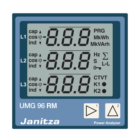
Page 34: Operation
UMG 96RM Operation programmed, the user arrives directly in the first The UMG 96RM is operated using buttons 1 and 2. Measured values and programming data appears programming menu. Programming mode is indicated by the text "PRG" on the display. on a liquid crystal display. - Page 35 UMG 96RM Maximum value, HT/import Minimum value, NT/export Mean value Programming mode Sum measurement Phase conductor- Phase conductor Password CT: Current transformer VT: Voltage transformer K1: Output 1 K2: Output 2 Button 2 Export Button 1...
-
Page 36: Parameters And Measured Values
UMG 96RM Parameters and measured values Example of the parameter display All parameters necessary for operating the UMG 96RM, On the UMG 96RM display e.g. the current transformer data, and a selection of the value "001" is shown as frequently required measured values are stored in the the content of address "000". -
Page 37: Button Functions
UMG 96RM Button functions Display mode Programming mode Change mode Change mode Password simultaneous simultaneous Browse Browse Programming short menu 1 short Measured Programming values 1a menu 2 long Programming Measured Measured menu 3 long values 2a values 2b long short Programming Programming... -
Page 38: Configuration
UMG 96RM Configuration Applying the supply voltage Attention! Supply voltages that do not correspond To configure the UMG 96RM, the supply voltage must to the nameplate information can lead be connected. to device malfunction or destruction. The level of supply voltage for the UMG 96RM can be found on the nameplate. - Page 39 UMG 96RM Current and voltage transformers The transformer ratios for each of the three current and voltage measurement inputs can be individually programmed in the Gri- dVis software included in the scope of delivery. Only the transformer ratio of the respective group of current measurement inputs or voltage measurement inputs is adjustable on the device.
-
Page 40: Programming Current Transformers
UMG 96RM Programming current transformers Current transformer secondary current input • Only 1 A or 5 A can be set as the secondary current. Switching to programming mode • Select the secondary current with button 1. • Simultaneously press buttons 1 and 2 in order • Change the flashing digit with button 2. -
Page 41: Programming Voltage Transformers
UMG 96RM Programming voltage transformers Current transformer, primary • Switch to the programming mode as described. The Programming mode symbols for the programming mode (PRG) and for the Units display current transformer (CT) appear. • Use button 2 to switch to the voltage transformer Current transformer, secondary setting. -
Page 42: Programming Parameters
UMG 96RM Programming parameters Fig. Password request If a password was set, Switching to programming mode it can be entered using buttons 1 and 2. • Switch to the programming mode as described. The symbols for the programming mode (PRG) and for the current transformer (CT) appear. - Page 43 UMG 96RM Device address (addr. 000) Mean value If several devices are connected to one another Mean values are formed over an adjustable period via the RS485 interface, a master device can only for the current, voltage and power measured values. differentiate between these devices by means of their The mean values are identified with a bar above device addresses.
- Page 44 UMG 96RM Averaging method Minimum and maximum values After the set averaging time, the exponential averaging All measured values are measured and calculated every method used achieves at least 95% of the measured 9 periods. Minimum and maximum values are deter- value.
- Page 45 UMG 96RM Mains frequency (addr. 034) A voltage L-N of greater than 10V effective voltage must Adjustment range: 0, 45 .. 65 be present on at least one of the voltage measurement automatic frequency determination. inputs in order that the mains frequency can be detected The mains frequency is determined from automatically.
- Page 46 UMG 96RM Energy meter Reading the active energy The UMG 96RM has energy meters for active energy, Total active energy reactive energy and apparent energy. The active energy in this example is: 12 345 678 kWh The active energy in this example is: 134 178 kWh...
- Page 47 UMG 96RM Harmonics Total Harmonic Distortion (THD) Harmonics are the integer multiple of a mains frequency. THD is the ratio of the root mean square value of The voltage mains frequency for the UMG 96RM must harmonics to the root mean square value of the mains be in the range between 45 and 65 Hz.
- Page 48 UMG 96RM Measured value relay Changeover time (addr. 039) All measured values are calculated every nine periods Adjustment range: 0 .. 60 seconds and can be recalled once per second on the measured If 0 seconds are set, no changeover takes place between value displays.
- Page 49 UMG 96RM Display profile (addr. 037) Adjustment range: 0 .. 3 0 - Display profile 1, default setting. 1 - Display profile 2, default setting. 2 - Display profile 3, default setting. 3 - Customised display profile. The customised profiles (display change profile and display profile) can only be programmed via the GridVis software.
- Page 50 UMG 96RM User password (addr. 050) Clear energy meter (addr. 507) A user password can be programmed in order to impede The active, apparent and reactive energy meters can any accidental change to programming data. A switch only be cleared together. to the next programming menu can only be made after entering the correct user password.
- Page 51 UMG 96RM Rotation field direction LCD contrast (addr. 035) The rotation field direction of the voltages and the The preferred direction of viewing for the LCD is from frequency of phase L1 are shown on the display. "below". The user can adjust the LCD contrast of the The rotation field direction indicates the phase sequence LCD screen.
- Page 52 UMG 96RM Time recording Operating hours meter The UMG 96RM records the operating hours and the The operating hours meter measures the time for which total running time of each comparator the UMG 96RM records and displays measured values. The time of operating hours is measured with a resolution • where the time of operating hours is measured with of 0.1 h and is displayed in hours.
- Page 53 UMG 96RM Serial number (addr. 754) The serial number shown by UMG 96RM has 6 digits and is part of the serial number displayed on the name- plate. The serial number cannot be changed. Serial number display Serial number information on the nameplate: XX00-0000 Software release (addr.
-
Page 54: Commissioning
UMG 96RM Commissioning Applying the measured current The UMG 96RM is designed for connecting ../1 A Applying the supply voltage and ../5 A current transformers. Only AC currents and not DC currents can be measured • The level of supply voltage for the UMG 96RM can be via the current measurement inputs. -
Page 55: Rotation Field Direction
UMG 96RM Rotation field direction Checking the measurement Check the direction of the voltage rotation field on the If all voltage and current measurement inputs are correctly connected, the individual and sum power measured value display of the UMG 96RM. ratings are accurately calculated and displayed. -
Page 56: Check The Sum Power Ratings
UMG 96RM Check the sum power ratings If all voltages, currents and power ratings for the respective phase conductor are correctly displayed, the sum power ratings measured by the UMG 96RM must also be correct. For confirmation, the sum power ratings measured by the UMG 96RM should be compared with the energy of the active and reactive power meters at the power feed. -
Page 57: Rs485 Interface
UMG 96RM RS485 interface The data from the parameter and measured value list The system does not support broadcast can be accessed via the MODBUS RTU protocol with (addr. 0). CRC check to the RS485 interface. Address range: 1 .. 247 The message length must not exceed Factory default setting: 256 bytes. - Page 58 UMG 96RM Example: Reading the L1-N voltage The "response" from the UMG 96RM can then appear The L1-N voltage is stored in the measured value list as follows: under the address 3166. The L1-N voltage is stored in INT format. Description Note The UMG 96RM device address with the address = 01...
-
Page 59: Digital Outputs
UMG 96RM Digital outputs The UMG 96RM has 2 digital outputs. The following functions can be optionally assigned to the digital outputs: Digital output 1 Digital output 2 Address 200 = 0 Result of the comparator group 1 Address 202 = 0 Result of the comparator group 2 Address 200 = 1 Pulse output Address 202 = 1 Pulse output Address 200 = 2 Value from an external source... - Page 60 UMG 96RM Digital outputs - status indicators The status of the switching outputs is represented Since the display is only updated once in the UMG 96RM display by circular symbols. per second, faster changes of the output states cannot be displayed. State of digital output 1 State of digital output 2 States of the digital output...
-
Page 61: Pulse Output
UMG 96RM Pulse output Measured value selection (addr. 100, 101) Among other things, the digital outputs can also be used Enter the power value here that is to be issued as an for the output of pulses to meter the energy consumption. energy pulse. - Page 62 UMG 96RM Pulse length (addr. 106) The pulse length applies for both pulse outputs and is Due to the minimum pulse length and minimum pulse permanently fixed via parameter address 106. pause, the values in the table are for the maximum number of pulses per hour.
- Page 63 UMG 96RM Pulse value (addr. 102, 104) The pulse value specifies how much energy (Wh or varh) should correspond to a pulse. The pulse value is determined by the maximum connected load and the maximum number of pulses per hour. If the pulse value is specified with a positive sign, pulses will only be issued if the measured value also has a positive sign.
- Page 64 UMG 96RM Determining the pulse value External 230 V AC operating voltage Setting the pulse length 24 V DC Set the pulse length according to the requirements of the connected pulse receiver. UMG 96RM For a pulse length of 30 ms, for example, the UMG Switching and pulse outputs 96RM can issue a maximum number of 60,000 pulses (see Table "Maximum Pulse Number") per hour.
- Page 65 UMG 96RM Limit value monitoring Two comparator groups are available for monitoring a limit value. Comparator group 1 is assigned to digital output 1 and comparator group 2 is assigned to digital output 2. UMG 96RM State of digital output 1 Addr.
- Page 66 UMG 96RM Example: Current monitoring in the neutral line For the lead time of 60 seconds, any exceeding should be If the current in the neutral line is greater than 100 A minimised. for 60 seconds, the digital output 1 should trip for at least Address 112 = 60 seconds 2 minutes.
-
Page 67: Comparator
UMG 96RM Comparator Comparator group 1 Comparator A Comparator B Comparator C Two comparator groups, each with Measured value (addr. 110) Measured value (addr. 116) Measured value (addr. 122) 3 comparators, are available for Limit value (addr. 108) Limit value (addr. 114) Limit value (addr. - Page 68 UMG 96RM • Measured value (addr. 110,116,122,129,135,141) • Comparator result (addr. 610,611,612,613,614,615) The address of the measured value to be monitored The result from the comparison between the measured is in the measured value. value and the limit value is in the comparator result. If measured value = 0, the comparator is inactive.
- Page 69 UMG 96RM Measured value Limit value Exceedance 2 seconds Lead time 2 seconds Minimum turn-on time Comparator result...
-
Page 70: Service And Maintenance
UMG 96RM Service and maintenance Firmware update The device is subject to various safety tests prior to delivery and is marked with a seal. If a device is opened, the safety tests must be repeated. A warranty is only If a firmware update needs to be implemented for your given for unopened devices. -
Page 71: Error Messages
UMG 96RM Error messages The UMG 96RM shows three different error messages Symbol for an error on the display: message - warnings, Error cause - serious error and - metering range exceedances. Description of the error If there are warnings and serious errors, the error message is indicated by the symbol "EEE"... - Page 72 UMG 96RM Warnings Internal causes of the error Warnings less serious errors The UMG 96RM can usually determine the cause of acknowledged with buttons 1 or 2. The measured values an internal error and then report it with the following error continue to be recorded and displayed.
- Page 73 UMG 96RM Metering range exceedance Examples Metering range exceedances are displayed for as long as they are present and cannot be acknowledged. A metering range is exceeded if at least one of the three voltage or current measuring inputs is outside of its A = current circuit specified metering range.
- Page 74 UMG 96RM Parameters of the metering range exceedance A continuative error description is stored encoded in the parameters of the metering range exceedance (addr. 600) in the following format: 0 x F F F F F F F F Phase 1: Phase 2: Phase 3: Example: Error in phase 2 in the current circuit:...
- Page 75 UMG 96RM...
- Page 76 UMG 96RM Procedure in case of error Possibility of error Cause Help No display External fuse for the power supply has Replace fuse. tripped. No current display Measurement voltage not Connect measurement voltage. connected. Measurement current not connected. Connect measurement current. The displayed current is too large or too Current measurement in the wrong phase.
- Page 77 UMG 96RM Possibility of error Cause Help Ind./cap. phase shift The current circuit is assigned to the Check and correct the connection if wrong voltage circuit. necessary. Real power is too small or too large. The programmed current transformer ratio Reading and programming the current is incorrect.
-
Page 78: Technical Data
UMG 96RM Technical data General Net weight 290 g Device dimensions approx. l = 42 mm, b = 97 mm, h = 100 mm Service life of the backlight 40,000 hours (50% of initial brightness) Transport and storage The following information applies for devices that are transported or stored in their original packaging. Free fall Temperature K55 (-25 °C to +70 °C) - Page 79 UMG 96RM Supply voltage Installation overvoltage category 300V CAT II Protection of the power supply (fuse) 6 A, type C (approved by UL/IEC) Nominal range 95V - 240V (45..65Hz) or DC 100V - 300V Working area +-10% from the nominal range Power consumption max.
- Page 80 UMG 96RM Connection capacity of the terminals (outputs) Rigid/flexible 0.14 - 1.5 mm , AWG 28-16 Flexible with ferrules without plastic sleeve 0.25 - 1.5 mm Flexible with ferrules with plastic sleeve 0.25 - 0.5 mm Tightening torque 0.22 - 0.25 Nm Stripping length 7 mm Voltage metering...
- Page 81 UMG 96RM Current measurement Metering range 0 .. 5 Arms (max. overload 7 Arms ) Crest factor 1.98 Resolution 0.1 mA (display 0.01 A) Overvoltage category 300 V CAT II Rated surge voltage 2 kV Power consumption approx. 0.2 VA (Ri=5 mOhm) Overload for 1 sec.
-
Page 82: Parameters Of Functions
UMG 96RM Parameters of functions Function Symbol Accuracy class Metering range Display range Total real power (IEC61557-12) 0 .. 15.3 kW 0 W .. 9999 GW * Total reactive power QA, Qv (IEC61557-12) 0 .. 15.3 kvar 0 varh .. 9999 Gvar * Total apparent power SA, Sv (IEC61557-12) - Page 83 UMG 96RM Function Symbol Accuracy class Metering range Display range Current harmonics Class 1 (IEC61000-4-7) up to 2.5 kHz 0 A .. 9999 kA THD of the current THDi (IEC61557-12) up to 2.5 kHz 0 % .. 999 % THD of the current THD-Ri (IEC61557-12) up to 2.5 kHz...
-
Page 84: Table 1 - Parameter List
UMG 96RM Parameter and Modbus address list The following excerpt from the parameter list contains A complete overview of the parameters and settings that are necessary for proper operation of the measured values is filed in the document UMG 96RM, such as current transformers and device "Modbus Address List"... - Page 85 UMG 96RM Address Format RD/WR Unit Note Adjustment Range Default FLOAT RD/WR Current transformer I2, sec. 1..5 FLOAT RD/WR Voltage transformer V2, prim. 0..1000000 FLOAT RD/WR Voltage transformer V2, sec. 100, 400 FLOAT RD/WR Current transformer I3, primary 0..1000000 FLOAT RD/WR Current transformer I3, sec.
- Page 86 UMG 96RM Address Format RD/WR Unit Note Adjustment Range Default SHORT RD/WR Address of the measured value, Digital output 1 0..32000 SHORT RD/WR Address of the measured value, Digital output 2 0..32000 FLOAT RD/WR Pulse value, Digital output 1 -1000000..+1000000 FLOAT RD/WR Pulse value,...
- Page 87 UMG 96RM Address Format RD/WR Unit Note Adjustment Range Default FLOAT RD/WR Comparator 1C, Limit value -1000000..+1000000 SHORT RD/WR Comparator 1C, Address of the measured value 0..32000 SHORT RD/WR Comparator 1C, Minimum turn-on time 0..32000 SHORT RD/WR Comparator 1C, Lead time 0..32000 SHORT RD/WR...
- Page 88 UMG 96RM Address Format RD/WR Unit Note Adjustment Range Default SHORT RD/WR Comparator 2C, lead time 0..32000 SHORT RD/WR Comparator 2C, Operator “>=” = 0 “<” = 1 SHORT RD/WR Select the source for Digital output 1 0..4 SHORT RD/WR Digital output 1 inverter 0..1 SHORT...
- Page 89 UMG 96RM Address Format RD/WR Unit Note Adjustment Range Default SHORT RD/WR Year 0..99 SHORT RD/WR Month 0..12 SHORT RD/WR 0..31 SHORT RD/WR Hour 0..24 SHORT RD/WR Minute 0..59 SHORT RD/WR Second 0..59 UINT RD/WR Metering range exceedance 0..0xFFFFFFFF SHORT RD/WR Modbus value for output 1 0, 1...
-
Page 90: Table 2 - Modbus Address List
UMG 96RM Table 2 - Modbus address list (frequently used measured values) The addresses in the range from 0-999 A complete overview of the parameters and listed in this document can be adjusted measured values is given in the "Modbus directly on the device. - Page 91 UMG 96RM Modbus Address Address Above display Format RD/WR Unit Note 19036 float Fund. reactive power (mains frequ.) Q L1 19038 float Fund. reactive power (mains frequ.) Q L2 19040 float Fund. reactive power (mains frequ.) Q L3 19042 float Sum;...
- Page 92 UMG 96RM Modbus Address Address Above display Format RD/WR Unit Note 19098 float varh Reactive energy, inductive, L3 19100 float varh Reactive energy L1..L3, ind. 19102 float varh Reactive energy, capacitive, L1 19104 float varh Reactive energy, capacitive, L2 19106 float varh Reactive energy, capacitive, L3...
- Page 93 UMG 96RM...
-
Page 94: Dimensional Drawings
UMG 96RM Dimensional drawings Cutout dimensions: Cutout dimensions: 92 x 92 +0.8 +0.8 Rear view Side view max. 6... - Page 95 UMG 96RM Bottom view...
-
Page 96: Overview Of Measured Value Displays
UMG 96RM Overview of measured value displays Measured values Mean values Maximum values Minimum values L1-N voltage L1-N voltage L1-N voltage L1-N voltage L2-N voltage L2-N voltage L2-N voltage L2-N voltage L3-N voltage L3-N voltage L3-N voltage L3-N voltage Measured values Mean values Maximum values Minimum values... - Page 97 UMG 96RM Measured values Mean values Maximum values L1 apparent power L1 apparent power L1 apparent power L2 apparent power L2 apparent power L2 apparent power L3 apparent power L3 apparent power L3 apparent power Measured value Mean value Maximum value Apparent power Apparent power Apparent power...
- Page 98 UMG 96RM Maximum value Maximum value Maximum value Distortion factor Distortion factor Distortion factor (THD) (THD) (THD) U L1 U L2 U L3 Maximum value Maximum value Maximum value Distortion factor Distortion factor Distortion factor (THD) (THD) (THD) I L1 I L2 I L3 Measured value...
- Page 99 UMG 96RM Measured value Measured value Measured value (ind) Reactive energy Reactive energy Reactive energy cap. ind. Operating hours Comparator 1 Comparator 6 meter 1 Total running time Total running time Measured value Measured value Measured value 1st. harmonic 3rd. harmonic 15th.
- Page 100 UMG 96RM Measured value Measured value Measured value 1st. harmonic 3rd. harmonic 15th. harmonic I L2 I L2 I L2 Measured value Measured value Measured value 1st. harmonic 3rd. harmonic 15th. harmonic I L3 I L3 I L3 Maximum value Maximum value Maximum value 1st.
- Page 101 UMG 96RM Maximum value Maximum value Maximum value 1st. harmonic 3rd. harmonic 15th. harmonic I L2 I L2 I L2 Maximum value Maximum value Maximum value 1st. harmonic 3rd. harmonic 15th. harmonic I L3 I L3 I L3 Even and odd harmonics up to the 40th order can be called up via the GridVis software and can be viewed in the software.
-
Page 102: Declaration Of Conformity
UMG 96RM Declaration of conformity The UMG 96RM fulfills the following protection requirements: Directive 2004/108/EC in conjunction with DIN EN61326-1:2006-10 (IEC 61326-1) as well as directive 2006/95/EC in conjunction with DIN EN 61010-1:2002-08 (IEC 61010-1) Observed standards: Interference resistance DIN EN 61326-1:2006-10 (IEC 61326-1) Electrical equipment for measurement, control and laboratory use –... -
Page 103: Connection Example
UMG 96RM Connection example UMG 96RM Digital outputs Basic device RS485 Supply voltage Voltage input Current input UL/IEC approved overcurrent protection device (6 A, type C) UL/IEC approved overcurrent protection device (10 A, type C) Jumpers (external) 230V/400V 50Hz... -
Page 104: Brief Instructions
UMG 96RM Brief instructions Current transformer setting, primary current Changing the current transformer setting Display Programming mode Switch to programming mode: Current transformer setting, • Simultaneously press buttons 1 and 2 for approximately secondary current 1 second in order to switch to programming mode. Current transformer symbol The symbols for the programming mode (PRG) and for (only in programming mode)
Need help?
Do you have a question about the UMG 96 RM and is the answer not in the manual?
Questions and answers