janitza UMG 804 User Manual And Technical Data
Bcm power analyser
Hide thumbs
Also See for UMG 804:
- User manual and technical data (40 pages) ,
- User manual and technical data (86 pages) ,
- Installation manual (36 pages)

Related Manuals for janitza UMG 804


Summary of Contents for janitza UMG 804
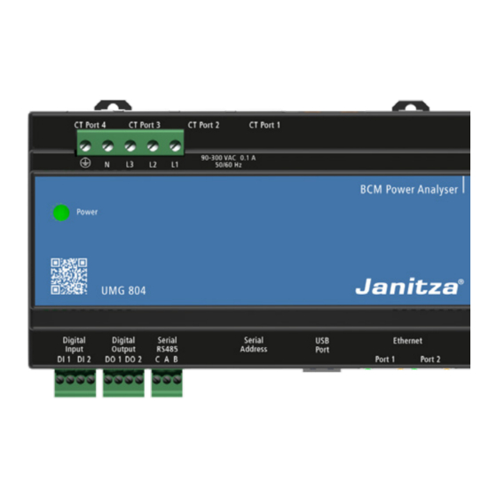
- Page 1 BCM Power Analyser UMG 804 User Manual and Technical Data Fig. UMG 804 (24 V), optional Janitza electronics GmbH Vor dem Polstück 6 35633 Lahnau, Gemany Support tel. +49 6441 9642-22 E-mail: info@janitza.com www.janitza.com...
- Page 2 · This equipment must only be installed and serviced by qualified electrical personnel. · Do not use this product for life or safety For Janitza measurement devices and compo- applications. nents, use only current transformers intended for · Do not install this product in hazardous or measuring purposes (“transformers”)!
- Page 3 Information and specifications can be changed at any time. Please consult www.janitza.com for information on the current version. The English version is the original version of the documentation.
-
Page 4: Table Of Contents
9. 1. 2 Installation and Placement of Current Transformers 9. 1. 3 Cable Ports and Circuit Designation 9. 1. 4 Detection by the UMG 804 9. 2 DIN Rail CT Interface Floating Boards 10. Voltage Input /Electrical Connections 10. 1 Voltage input 230 V AC 10. - Page 5 UMG 804 11. Serial Communications 12. Ethernet Communications 13. Configuration of UMG 804 Settings 13. 1 Configuring via direct Modification of the CSV file 13. 2 Configuring via the Onboard Web Console (firmware version 1.109 or higher) 13. 2. 1 Main Status Page 13.
- Page 6 UMG 804 www.janitza.com 14. 8 Single Row Sequential Configuration – DIN Rail CT Interface Board Orientation 14. 9 Single Row Odd Even Configuration – Circuit to Register Maps 14. 10 Single Row Odd Even Configuration – DIN Rail CT Interface Board Orientation...
- Page 7 UMG 804...
-
Page 8: General Information
· Metal or commission a certified disposal company with the scrapping. Copyright notice © 2019 - Janitza electronics GmbH - Lahnau. Safety All rights reserved. Any duplication, processing, distribution and any The safety chapter contain notes that must be other kind of use, even in part, is prohibited. -
Page 9: Danger Levels
UMG 804 Danger levels Read and understand the user manual before installation, operation, maintenance and use of the Warning notices and safety instructions are device. highlighted by a warning symbol and the danger levels are presented as follows depending on the... -
Page 10: Electrically Qualified Personnel
Janitza measurement devices or their compo- nents can lead to injuries and even death or to material damage! · Do not use Janitza measurement devices or components for critical switching, control or pro- tection applications where the safety of persons and property depends on this function. -
Page 11: System Overview
24 x 24 x 24 x 24 Fig. 1: DIN Rail CT Interface Boards connect to the Smart Ports on the UMG 804 using network cables. INFORMATION The UMG 804 can also be connected via Splitcore CT with Molex connector (available at Janitza electronics GmbH) -
Page 12: Order Information
Order information Articel Short name Item no.: UMG 804 230 V AC UMG 804 14.02.001 UMG 804 230 V AC Advanced UMG 804 14.02.002 UMG 804 24 V DC UMG 804 14.02.009 UMG 804 24 V DC Advanced UMG 804 14.02.010... -
Page 13: Specifications
UMG 804 Specifications General Device dimensions (approx.) w=158.7 mm, h=108.5 mm, d=59.2 mm (w=6.248 in, h=4.271 in, d=2.330 in) Transport and storage The following information applies to devices which are transported or stored in the original packaging. Temperature -40 °C to 70 °C (-40 °F to 158° F) - Page 14 UMG 804 www.janitza.com Current measurement on modules Rated current 0 .. 600 A (external current transducer dependant) Resolution 0.01 A Crest factor 3.75 @ 100 % of 0.333 V signal Overload for 1 s 200 % Voltage measurement The voltage measurement inputs are suitable for measurements in the following power supply systems...
- Page 15 36 (1.420) 2,0 (78.74) 0.5* DIN-Rail * in combination with the UMG 804 and the DIN Rail CT Interface Floating Board / DIN Rail CT Interface Card Further information can be found in the separate data sheet for the current transformers.
-
Page 16: Monitored Parameters And Feature Sets
UMG 804 www.janitza.com Monitored Parameters and Feature Sets Monitored Parameters UMG 804 Monitor Feature Sets Monitors are available with a Standard and Advanced feature set. Version Circuit Input Monitored Parameter Feature Level Level Standard Advanced Current per phase • •... -
Page 17: Connector Overview
USB SD card on Advanced UMG 804s. The USB port can be used to configure the UMG 804 using a USB thumb drive with up to 64 GB in capacity the configuration file. See the “Configuration”... -
Page 18: Umg 804 Installation
Once rail is in place push the circlips down on which the monitor is being installed before to secure the enclosure in place. starting the installation. The UMG 804 can be housed in existing enclosures Unlock where permitted by code or inside standard electrical enclosures. -
Page 19: Connection Of Din Rail Ct Interface Boards
Be sure that the mounting area allows for adequate wire bending radiuses per local and national electrical codes. The UMG 804 is installed by mounting on standard 35 mm DIN rail. The enclosure can be mounted in any orientation. Secure the DIN rail using a mechanical fastener such as sheet metal screw or bolt to a secure surface. - Page 20 There are four Smart Port receptacles on the Consult the section on this manual for the specific UMG 804. It is critical the correct Smart Port CT interface cards to determine the correct Smart receptacle is assigned to the correct DIN Rail Port to CT interface card relationship.
-
Page 21: Din Rail Ct Interface Card
9.1.1 Current Transformer Types The DIN Rail CT Interface Card is designed to used 0.33V output CTs provided by Janitza. Other 0.33V CTs won`t work, Janitza does not warranty the performance if third party CTs are used. DO NOT USE unburdened i.e. current output, CTs as these will destroy the board as well as can pro- duce lethal voltages during installation. -
Page 22: Cable Ports And Circuit Designation
UMG 804 www.janitza.com Push to release conductor BLACK WIRE Insert CT Conductor WHITE Conductor Size: 16-20 AWG (0.5-1.5mm) WIRE Stripping length: 8mm Circuit Designations Fig. 9: Current Transformer installation CT installation: The current transformer is auto detecting and is not polarized. -
Page 23: Detection By The Umg 804
UMG 804 and the module is powered on, they will automatically be discovered upon power up of the UMG 804. A green LED on the DIN Rail CT Interface Card that will indicate if it is discove- red and communicating. To be properly communi- cating the LED will be pulsing at a 1Hz rate. -
Page 24: Din Rail Ct Interface Floating Boards
CT strip with the UMG 804. [2] Auxiliary CT Terminal Block: monitors up to [6] UMG 804: hosts up to four interface floating three auxiliary CTs per DIN Rail CT Interface boards. Floating Board, typically used to monitor main [7] Network Cable: used to connect Smart Ports to input circuits. -
Page 25: Voltage Input /Electrical Connections
Failure to follow these instructions will result in death or serious injury. The UMG 804 must be connected to the voltage source being monitored. The Voltage Input termi- nal serves as the both power supply to the monitor and voltage sensing (230 V version). -
Page 26: Voltage Input 24 V Dc (Optional)
UMG 804 www.janitza.com 10.3 Voltage input 24 V DC (optional) 24 V DC Fig. 24: 24 V DC NOTE Devices that can be operated with DC voltage are protected against polarity reversal 10.2 Acceptable wiring configurations The monitor may be connected to any wiring configuration shown in the following figure except for corner grounded delta circuits. -
Page 27: Serial Communications
UMG 804 11. Serial Communications The UMG 804 supports both Modbus TCP/IP and Modbus RTU serials communications. Connect the shielded 2 wire cable to the 2-wire Modbus RS-485 network with the serial interface jack. Mechanically secure the RS-485 cable(s) where USB PORT they enter the electrical panel. -
Page 28: Ethernet Communications
UMG 804 www.janitza.com 12. Ethernet Communications can be used to link additional UMG 804s or other The UMG 804s equipped with dual managed third party Ethernet devices to the network. To Ethernet ports. Either port can be used to com- configure the IP settings see the configuration at municate with the device. -
Page 29: Configuration Of Umg 804 Settings
It can then 1. Via the USB Interface using a USB Flash Drive be loaded into the UMG 804 by power cycling the with the Configuration File / spreadsheet. This device with the USB drive installed. Note that the is the recommended and most flexible method. -
Page 30: Configuring Via The Onboard Web Console (Firmware Version 1.109 Or Higher)
UMG 804 and select the [Network] tab on the web console. The default IP address is 192.168.5.77 3. If the web console of the UMG 804 does not appear, ping the IP address using the windows command line prompt “ping 192.168.5.77” to confirm the communications link. -
Page 31: Main Status Page
UMG 804 13.2.1 Main Status Page · The Main Status Page indicates the identifying features of the UMG 804 including firmware ver- sion and connectivity status to interface devices connected to the Smart Ports. BCMS Main Hall The following information is displayed on the Main Status page. -
Page 32: Date And Time Reference
UMG 804 www.janitza.com 13.2.2 Date and Time Reference · The Date and Time can be synchronized by clicking on the Date button in the Main Status page. · This reference may be changed in the config.csv file or on the Homepage to reference the desired NTP server. -
Page 33: Smart Port Connectivity Status
UMG 804 13.2.3 Smart Port Connectivity Status · When a DIN Rail CT Interface Board i.e. DIN Rail CT Interface Card, is successfully connected to the smart port, there are two display options for this: State of Homepage the designated Smart Port (1-4) will display as CONNECTED on the Main Status page. -
Page 34: Ethernet Settings
Serial · The factory default IP is always 192.168.5.77 · The PC or device must be set to the same subnet as the IP address on the UMG 804 (see modify- ing subnet (i.e 192.168.5.XXX) on PC for more details). -
Page 35: Serial Communications Settings
UMG 804 13.2.5 Serial Communications Settings Ethernet The Serial Settings page allows for all serial based Serial settings to be configured. These settings may also be configured using the config.csv file via USB drive. INFORMATION All UMG 804s or devices sharing the same serial line must have unique addresses / slave IDs. -
Page 36: Data Console
UMG 804 www.janitza.com 13.2.6 Data Console The options under the Data menu allow for view- ing real time readings as well as waveform captu- res and voltage abnormalities. · True Meter Data: Displays data for “True Meters” · Busway Data: Display data for busway tap-offs circuits that are grouped to represent a single and end feeds. -
Page 37: Data Menu / True Meter Data Page
UMG 804 13.2.7 Data Menu / True Meter Data Page · The True Meter data page provides an overview of all data for all True Meters. True Meters are groups of individual circuits that are combined to represent a single two-phase or three-phase circuit breaker allowing total data for the breaker to be presented. -
Page 38: Data Menu / Detail Data Page
UMG 804 www.janitza.com 13.2.8 Data Menu / Detail Data Page · The Detail Data page presents readings for all channels / circuits connected to the meter. · Channels are organized according to the Smart Port on the meter they are connected to. - Page 39 UMG 804 Setting Alarm Thresholds · Alarm thresholds can be set on the Detail Data page under the Data Menu. · Voltage thresholds are set using the Update Set- tings button under the Voltage Alarm. INFORMATION Setting any threshold to “0” will disable the alarm.
-
Page 40: Waveform Capture
UMG 804 www.janitza.com 13.2.9 Waveform Capture · The Waveform Capture function will capture up to six cycles (256 data points) of a waveform for all of the affected 96 channels in the event the voltage or current exceeds the waveform capture thresholds. - Page 41 UMG 804 Viewing and Downloading · To view a waveform capture, select the capture from the drop down menu which uses the dd/ mm/yy/hh/mn/ss file name and then select the phase and circuit / channel from the drop down menu followed by selecting Add to plot.
-
Page 42: Data Menu / Busway Configuration
UMG 804 www.janitza.com 13.2.10 Data Menu / Busway Configuration Available on request. -
Page 43: Data Menu / Voltage Events (Firmware Version 1.109 Or Higher)
UMG 804 13.2.11 Data Menu / Voltage Events (firmware version 1.109 or higher) Any voltage event that violates the CBEMA / ITIC power quality window will be captured and written to the USB flash drive. · A USB drive must be installed in the meter (no larger than 32 GB) to capture events. -
Page 44: Configuration / General Settings
Point Map: The monitor is capable of supporting two different register maps. The standard register map is the UMG 804 Point Map that provides access to all of the features the module offers. System Voltage: Provide the nominal system voltage (line to line) for the source. If a line to neutral single-phase source is being used input the line to neutral voltage. -
Page 45: Configuration / Ct Size
UMG 804 13.2.13 Configuration / CT Size The CT (current transformer) size configuration set- ting provides current transformer nominal ampera- ge values for all circuit positions. This is critical as it affects the scaling of currents. · All CTs used must 0.33 V output. -
Page 46: Configuration / Breaker Size
UMG 804 www.janitza.com 13.2.14 Configuration / Breaker Size · The breaker size configuration setting provides trip ratings for each circuit breaker on each circuit. · This is used in the calculations of the over and under current calculations. · To determine which channel corresponds to... -
Page 47: Configuration / Voltage Phase
UMG 804 13.2.15 Configuration / Voltage Phase · The Voltage Phase Assignment assigns a voltage phase (L1, L2, L3) to each channel in the event non-sequential panel type or receptacle types are being used. · The default is L1-L2-L3 in sequential order. -
Page 48: Configuration / True Meter
UMG 804 www.janitza.com 13.2.16 Configuration / True Meter · True Meter Mapping allows individual circuits/ channels to be grouped as one, two or three phase meters and read as a single meter. · For example: if channels 1,2,3 are a three-phase... - Page 49 UMG 804 True Meter Assignement - Example · Accessing Modbus data for friendly circuits is · In the below example each channel / pole on a made easy as the registers start at base 10,000 breaker is assigned a common True Meter num- for True Meter 1 and then advance by 500’s.
-
Page 50: Configuration / System
Save Settings to File on USB This function will download all of the configuration settings from the UMG 804 to a .csv file on a USB drive installed in the UMG 804. This can then be used to verify settings as well as duplicate settings on other UMG 804s. - Page 51 UMG 804 Updates Reboot the UMG 804 1. Select Reboot the UMG 804 after 60 seconds The firmware in the UMG 804 can be updated lo- even if “upload in progress” message is still cally or remotely (Firmware 1.109 and higher) over present.
-
Page 52: Din Rail Ct Interface Board Configuration
UMG 804 www.janitza.com 14. DIN Rail CT Interface Board Configuration 14.1 DIN Rail CT Interface Card Settings are managed by the Smart Port Configu- ration drop-down menu under the Configuration > General Settings. The DIN Rail CT Interface Card should always use the “Sequential”... -
Page 53: Panel Configuration Maps - Chart Explanation
Modbus register. INFORMATION This mapping is exclusively for the UMG 804 point map and is different for the Schneider Equivalent point map. Refer to the Schneider Equivalent point map tables for details. -
Page 54: Top Feed Configuration - Circuit To Register Maps
UMG 804 www.janitza.com 14.3 Top Feed Configuration – Circuit to Register Maps... -
Page 55: Top Feed Configuration - Din Rail Ct Interface Board Orientation
UMG 804 14.4 Top Feed Configuration – DIN Rail CT Interface Board Orientation DIN Rail CT Interface Floating Board PANEL 2 PANEL 1... -
Page 56: Bottom Feed Configuration - Circuit To Register Maps
UMG 804 www.janitza.com 14.5 Bottom Feed Configuration – Circuit to Register Maps... -
Page 57: Bottom Feed Configuration - Din Rail Ct Interface Board Orientation
UMG 804 14.6 Bottom Feed Configuration – DIN Rail CT Interface Board Orientation DIN Rail CT Interface Floating Board PANEL 2 PANEL 1... -
Page 58: Single Row Sequential Configuration - Circuit To Register Maps
UMG 804 www.janitza.com 14.7 Single Row Sequential Configuration – Circuit to Register Maps... - Page 59 UMG 804 14.8 Single Row Sequential Configuration – DIN Rail CT Interface Board Orientation DIN Rail CT Interface Floating Board PANEL 2 PANEL 1...
- Page 60 UMG 804 www.janitza.com 14.9 Single Row Odd Even Configuration – Circuit to Register Maps...
- Page 61 UMG 804 14.10 Single Row Odd Even Configuration – DIN Rail CT Interface Board Orientation DIN Rail CT Interface Floating Board PANEL 2 PANEL 1...
- Page 62 UMG 804 www.janitza.com 14.11 Sequential Configuration – Circuit to Register Maps Sequential configuration is used for the DIN Rail CT Interface Card CT. All the CT terminals will equal the channel number for the HTML display for their respective Smart Ports.
- Page 63 UMG 804...
- Page 64 Janitza electronics GmbH Vor dem Polstück 6 35633 Lahnau, Germany Tel.: +49 6441 - 9642-0 E-mail: info@janitza.com info@janitza.com | www.janitza.com...
Need help?
Do you have a question about the UMG 804 and is the answer not in the manual?
Questions and answers