janitza UMG 804 User Manual And Technical Data
Bcm power analyser
Hide thumbs
Also See for UMG 804:
- User manual and technical data (64 pages) ,
- User manual and technical data (86 pages) ,
- Installation manual (36 pages)

Related Manuals for janitza UMG 804


Summary of Contents for janitza UMG 804
- Page 1 BCM Power Analyser UMG 804 User Manual and Technical Data Janitza electronics GmbH Vor dem Polstück 6 35633 Lahnau, Gemany Support tel. +49 6441 9642-22 Fax +49 6441 9642-30 E-mail: info@janitza.com www.janitza.com...
- Page 2 UMG 804 www.janitza.com Safety Information conductors with approved current limiting devices DANGER suitable for protecting the wiring. HAZARD OF ELECTRIC SHOCK, Control system design must consider the potential EXPLOSION, OR ARC FLASH failure modes of control paths and, for certain cri- ·...
- Page 3 UMG 804 This symbol indicates an electrical shock hazard exists. Documentation must be consulted where this symbol is used on the product.
- Page 4 UMG 804 www.janitza.com Information sur la sécurité Utilisation dans un environnement de pollution DANGER de niveau 2 ou inférieur uniquement. Un RISQUE DE CHOC ÉLECTRIQUE, D’EXPLO- environnement de niveau de pollution 2 doit SION OU D’ARC ÉLECTRIQUE contrôler le niveau de pollution conductrice et la ·...
- Page 5 UMG 804 Pour plus d’informations sur les latences de transmission ou sur les défaillances de la liaison possibles, reportez-vous à la norme NEMA ICS 1.1 (dernière édition). Safety Guidelines for the Appli- cation, Installation and Maintenance of Solid-State Controls (consignes de sécurité pour l’utilisation, l’installation et l’entretien de commandes electro-...
-
Page 6: Table Of Contents
UMG 804 www.janitza.com Content 1. General information 1. 1 Disclaimer 1. 2 Copyright notice 1. 3 Technical changes 1. 4 About this user manual 1. 5 Defective device/disposal 2. Safety 2. 1 Presentation of warning notices and safety instructions 2. 2 Danger levels 2. - Page 7 Information and specifications can be changed at any time. Please consult www.janitza.com for information on the current version. The English version is the original version of the documentation.
-
Page 8: General Information
· Metal or commission a certified disposal company with the scrapping. Copyright notice © 2019 - Janitza electronics GmbH - Lahnau. Safety All rights reserved. Any duplication, processing, distribution and any The safety chapter contain notes that must be other kind of use, even in part, is prohibited. -
Page 9: Danger Levels
UMG 804 Danger levels Read and understand the user manual before installation, operation, maintenance and use of the Warning notices and safety instructions are device. highlighted by a warning symbol and the danger levels are presented as follows depending on the... -
Page 10: Electrically Qualified Personnel
UMG 804 www.janitza.com Electrically qualified personnel WARNING To prevent personal injuries and property damage, Risk of injury due to electric voltage! only electrically qualified personnel may work on Serious personal injuries or death may occur! the devices and their components, assemblies, Therefore, please observe the following: systems and circuits. - Page 11 UMG 804...
-
Page 12: System Overview
UMG 804 www.janitza.com System Overview The Core Module Multi-Circuit Monitoring System The Core Module can communicate via Modbus is designed to measure the current, voltage, and TCP/IP, Modbus RTU as well as provides access energy consumption and other critical power to real time and logged data via an on board web parameters up to 96 circuits. -
Page 13: Order Information
UMG 804 Order information Articel Item no.: UMG 804 14.02.001 UMG 804 Advanced 14.02.002 DIN Rail Interface Board 14.02.003 Floating Interface Board 14.02.004 Solid Core CT Strip EU 14.02.005 Solid Core CT Strip US 14.02.006 Adv. Voltage Detection SC CT Strip EU18mm 14.02.007... -
Page 14: Specifications
UMG 804 www.janitza.com Specifications Voltage Inputs Measurement Voltage / Control 90 to 300 VAC line-to-neutral, 50/60 Hz Power Overload Protection Internally fused (0.5 A @ 300 VAC) Current Consumption <0.1A @ 277 VAC Accuracy and Monitoring Power/Energy IEC 62053-21 Class 1, ANSI C12.1-2008 System Accuracy (including branch... - Page 15 UMG 804 Wire Size Range Voltage Connection 24 to 12 AWG I/O and Serial Connections 22 to 16 AWG Aux. Terminals on CT Interface 26 to 16 AWG Boards Terminal Block Torque Voltage Connection 4.4 to 5.3 in-lb (0.5 to 0.6 N-m) I/O and Serial Connections 3.5 to 4.4 in-lb (0.4 to 0.5 N-m)
-
Page 16: Monitored Parameters And Feature Sets
UMG 804 www.janitza.com Monitored Parameters and Feature Sets Monitored Parameters Core Module Monitor Feature Sets Monitors are available with a Standard and Advanced feature set. Version Circuit Input Monitored Parameter Feature Level Level Standard Advanced Current per phase • •... -
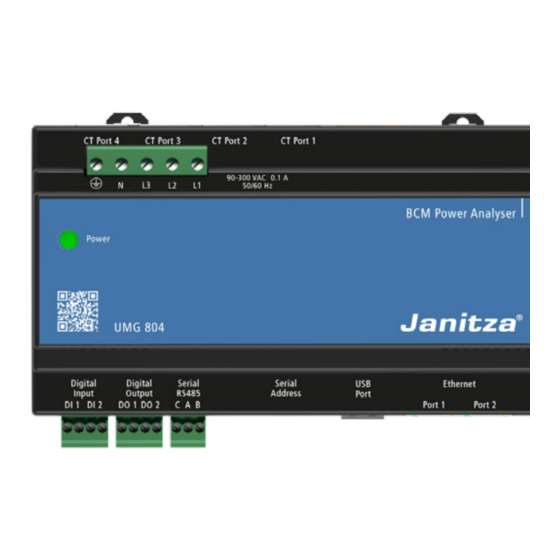
Page 17: Connector Overview
UMG 804 Connector Overview Fig. 3: Connector Overview Ethernet Ports: The Core Module is Digital Output: Two isolated dry contact equipped with two Ethernet ports to digital outputs rated at 30 V x 0.1 A. facilitate easy daisy chaining of network connections. -
Page 18: Core Module Installation
UMG 804 www.janitza.com Core Module Installation Mount the enclosure on the DIN rail by lifting up circlips and placing enclosure over the rail as shown. Once rail is in place push the circlips down to secure the enclosure in place. -
Page 19: Connection Of Interface Boards
UMG 804 Connection of Interface Boards There are different application specific Current Transformer Interface Boards that connect to Smart Ports on the Core Module using network cable. CAUTION Cables are eight conductor network / Ethernet Note that the when the Ethernet cable is run in the same raceway or conduit area it must have cables with RJ45 connector terminations;... -
Page 20: Cable Ports And Circuit Designation
UMG 804 www.janitza.com Panel 1 Panel 2 Cable Ports and Circuit Designation section on this manual for the specific CT interface ModBus Address “X” ModBus Address “X”+1 cards to determine the correct Smart Port to CT There are four Smart Port receptacles on the interface card relationship. -
Page 21: Multi-Circuit Monitor Interface Board Installation
DIN rail. 10.2 Current Transformer Types The interface board is designed to used 0.33V output CTs provided by Janitza. Other 0.33V CTs will also work but Janitza does not warranty the performance if third party CTs are used. DO NOT... -
Page 22: Cable Ports And Circuit Designation
UMG 804 www.janitza.com Push to release conductor BLACK WIRE Insert CT Conductor WHITE Conductor Size: 16-20 AWG (0.5-1.5mm) WIRE Stripping length: 8mm Circuit Designations Fig. 9: Current Transformer installation LINE SIDE CT installation orientation should have the label CT LABEL... -
Page 23: Discovery Of Ct Interface Card By The Core Module
UMG 804 BOARD 4 BOARD 3 BOARD 2 BOARD 1 4 3 2 1 Fig. 11: Current Transformer Interface Card wiring 10.5 Discovery of CT Interface Card by the Core Module Once the CT Interface Card(s) are plugged into the IMPORTANT: CT Strips and Cards can only be discovered upon power up of the Core Module. -
Page 24: Solid Core Ct Strips Interface Board Installation
UMG 804 www.janitza.com 11. Solid Core CT Strips Interface Board Installation Solid core CT strips are used for new installations on panelboards. There are two versions of the CT strip designed to match specific breaker spacing and pole count; an 18mm x 18 CT strip and 0.75”... - Page 25 UMG 804 18 mm center to center CT strip Dimensions 16.4” (417 mm) 1.69” (43 mm) 1.3” (32 mm) 0.9” (21.2 mm) 0.4” (10 mm) 0.7” (18 mm) opening on center Fig. 14: 18 mm CT strip dimensions 0.75” center to center CT strip Dimensions 20.0 (508 mm)
-
Page 26: Placement And Orientation Of Solid Core Ct Strips
UMG 804 www.janitza.com 12. Placement and Orientation of Solid Core CT Strips CT strips can be installed in a number of configu- tion of RJ45 cable jack. It is critical that each CT rations designed to match the panelboard layout strip be connected to the correct Interface Card and pole numbering. -
Page 27: Channel Allocation Tables
UMG 804 12.1 Channel Allocation Tables CHANNEL ALLOCATION TABLES MCM CARD - SEQUENTIAL CONFIGURATION PANELBOARD CONFIGURATION (Base SINGLE ROW SINGLE ROW ODD EVEN BOTTOM FEED TOP FEED Slave ID) Native CT Terminal # SEQUENTIAL (Corresponding Circuit (Corresponding Circuit (Corresponding Circuit... - Page 28 [P1 33] [P1 30] [P1 18] [P1 26] [P1 18] [P1 34] [P1 31] [P1 20] [P1 24] [P1 20] UMG 804 www.janitza.com [P1 35] [P1 32] [P1 22] [P1 22] [P1 22] [P1 36] [P1 33] [P1 24] [P1 20]...
-
Page 29: Mounting Instructions: 18Mm Strip
UMG 804 12.2 Mounting Instructions: 18mm Strip The 18mm Solid Core CT strip is mounted using from the circuit breaker terminal to the edge of standard 35mm DIN rail. Each strip is supplied the CT strip. Once correctly positioned connect with 3 DIN clips to fasten to the rail. -
Page 30: Connection Of Auxiliary Ct Terminals
Si vous n’utilisez pas de TC de 0.33 V, vous ris- quez d’endommager la barrette de tomodensi- tométrie et de provoquer des blessures graves, voire mortelles, du fait que les TC à sortie de Janitza BCMs Point Map Connection: courant / courant peuvent entraîner des ten- CT Strip Panel sions mortelles. -
Page 31: Connection Of Ct Strips To Smart Ports
UMG 804 13. Connection of CT Strips to Smart Ports · Panelboard 1 shall be connected to ports 1 and 2. · Port 1 shall be the CT strip where CT position Important: Always use the correctly rated insula- number 1 is located per figure 21. -
Page 32: Voltage Input / Electrical Connections
0.2 A at any operational voltage. The monitor is fused internally but additional fusing may be required per local and national codes. Inline fuses are available from Janitza. G/E N VOLTAGE INPUT CONNECTOR 5.5 mm (0.22”) Max SOLID WIRE: 24-12 AWG / 0.205-3.31 MM²... -
Page 33: Acceptable Wiring Configurations
UMG 804 14.1 Acceptable wiring configurations The monitor may be connected to any wiring configuration shown in figure xx except for corner grounded delta circuits. Corner-grounded 4-Wire Wye 3-Wire 2-Wire 2-Wire 120/240V 3-wire (ungrounded) Delta - NOT ALLOWED Phase-Phase... -
Page 34: Ethernet Communications
UMG 804 www.janitza.com USB PORT SERIAL SERIAL RS-485 ADDRESS CABLE SHIELD S (-) (+) Fig. 26: Serial communications port and serial DIP switch address settings locations 16. Ethernet Communications The Core Module s equipped with dual managed be used to link additional Core Modules or other Ethernet ports. -
Page 35: Configuration Of Core Module Settings
UMG 804 17. Configuration of Core Module Settings 17.1 Configuration Methods The Core Module can be configured in three diffe- rent ways: 1. Via the USB Interface using a USB Flash Drive When all data entry is complete, select the red with the Configuration File / spreadsheet. -
Page 36: Configuring Via The Onboard Web Console
UMG 804 www.janitza.com 17.1.2 Configuring via the Onboard Web Console The onboard web console may be used to config- ure the serial or Ethernet communications param- eters but advanced configuration must be done using the spreadsheet or directly via a Modbus communications utility. - Page 37 UMG 804 The web console screen will have a menu with four tabs located at the top of the screen: MAIN TAB: The Main Status page lists the device (Core Mod- ule) specifics including the user defined parame- ters “Device Name”and “Device Location” as well as firmware version and MAC Address.
- Page 38 UMG 804 www.janitza.com DATA TAB: The Data tab provides access to real time data from the monitor. This is separated into a “Sum- mary Data” page which provides an overview of main input power and a “Detail Data” page which...
- Page 39 UMG 804 It is also possible to trigger manual waveform captures using the Waveform Capture function on the Waveform Capture page. The resulting data are waveforms for each channel will be stored on a usb stick as a CSV file. These can be viewed graphically using the waveform graphing template.
-
Page 40: Configuring Via Direct Modification Of The Csv File
“config.csv”. Janitza electronics GmbH Vor dem Polstück 6 D-35633 Lahnau Tel.: +49 6441 - 9642-0 E-Mail: info@janitza.de info@janitza.de | www.janitza.de Dok.-Nr. 2.063.003.0 | Stand 07/2019 | Technische Änderungen vorbehalten. Den aktuellen Status des Dokuments finden Sie im Download-Bereich auf www.janitza.de.
Need help?
Do you have a question about the UMG 804 and is the answer not in the manual?
Questions and answers