janitza UMG 509-Pro User Manual And Technical Data
Power quality analyzer
Hide thumbs
Also See for UMG 509-Pro:
- Installation instructions manual (14 pages) ,
- User manual and technical data (111 pages)

Related Manuals for janitza UMG 509-Pro


Summary of Contents for janitza UMG 509-Pro
- Page 1 Power Quality Analyzer UMG 509-Pro User manual and technical data Janitza electronics GmbH Vor dem Polstück 6 35633 Lahnau | Germany Support: +49 6441 9642-22 info@janitza.com | www.janitza.com...
- Page 2 UMG 509-PRO www.janitza.com UMG 509-Pro Power Quality Analyzer Doc. no.: 2.059.011.2.s 10/2022 The German version is the original edition of the documentation.
- Page 3 Nonetheless, we wish to point out that updates of this document are not always possible at the same time as technical refinements are implemented in our products. Please see our website under www.janitza.de for the current version. Please see our website under www.janitza.com for the current version.
-
Page 4: Table Of Contents
UMG 509-PRO www.janitza.com Table of contents 1. General Disclaimer Copyright notice Technical changes About this user manual Meaning of the symbols Defective device/disposal 2. Safety Display of warning notices and safety information Hazard levels Product safety Dangers when handling the device... - Page 5 UMG 509-PRO 4. Structure of the device Front panel and display Rear view 5. Mounting Installation location Mounting orientation Securing 6. Grid systems Three-phase 3-conductor systems Three-phase 4-conductor systems Nominal voltages 7. Installation Connection to a PC Ground wire connection...
- Page 6 UMG 509-PRO www.janitza.com 8. Interfaces Shielding RS-485 interface 8.2.1 Termination resistors Profibus interface 8.3.1 Connecting the bus lines Bus structure Ethernet interface 9. Digital inputs and outputs Digital inputs 9.1.1 S0 - Pulse input Digital outputs 10. Operation 10.1 Button assignment 10.2...
- Page 7 UMG 509-PRO 11.3.4 Mains frequency 11.3.5 Temperature 11.4 System 11.4.1 Password 11.4.2 Reset 11.5 Display 11.6 Colors 11.7 Enhancements 11.8 PTP configuration 11.8.1 Important Modbus parameters for the PTP configuration of the device 11.8.2 PTP parameter _MODE_NTP 11.8.3 Example: PTP timing according to IEEE 1588-2008 and clock types 12.
- Page 8 UMG 509-PRO www.janitza.com 13. Device homepage 13.1 Measured values 13.1.1 Brief overview 13.1.2 Detailed measured values 13.1.3 Charts 13.1.4 RCM - residual current measurement 13.1.5 Events 13.1.6 Transients 13.2 Power quality 13.3 Apps 13.3.1 Push Service 13.4 Information 13.4.1 Device information 13.4.2...
- Page 9 UMG 509-PRO 15. Technical data 15.1 Supply voltage 15.2 Voltage and current measurement 15.3 Residual current detection 15.4 Temperature measurement input 15.5 Digital inputs and outputs 15.6 Interfaces 15.7 Performance characteristics of functions 15.8 Dimensional drawings 16. Procedure in the event of a malfunction 17.
-
Page 10: General
Copyright notice · Online help for the network visualization software GridVis ® © 2022 - Janitza electronics GmbH - Lahnau. All rights reserved. Meaning of the symbols Any reproduction, processing, distribution or other use of this informational product, in whole or in The following pictograms are used in this manu- part, is prohibited. -
Page 11: Defective Device/Disposal
· When doing so, please bear the terms for trans- portation in mind. INFORMATION Please return defective or damaged devices to Janitza electronics GmbH in accordance with the shipping instructions for air or road freight (com- plete with accessories). Observe special regulations for devices with built-in... -
Page 12: Safety
UMG 509-PRO www.janitza.com Safety The chapter on Safety contains information which Hazard levels must be observed to ensure your personal safety Warning and safety information is marked by a and avoid material damage. warning symbol, and the hazard levels are shown... -
Page 13: Dangers When Handling The Device
· Do not use Janitza measurement devices or components for critical switching, control or protection applications where the safety of per- sons and property depends on this function. -
Page 14: Electrically Qualified Personnel
UMG 509-PRO www.janitza.com Electrically qualified personnel Safety information for handling current transformers and measurement devic- To avoid bodily injury and material damage, only es with residual current measurement electrically qualified personnel are permitted to work on the devices and their components, mod-... -
Page 15: Handling Batteries/Accumulators
· Only replace the battery with the same type death! or types recommended by Janitza! · Do not use devices with residual current · Observe the polarity when installing the measurement as a stand-alone protective battery! device. -
Page 16: Product Description
UMG 509-PRO www.janitza.com Product description Device description Incoming goods inspection The device is: The prerequisites for trouble-free and safe op- eration of this device include proper transport, · Intended for measurements in building installa- storage, setup and assembly, as well as proper tions, on distribution boards, circuit breakers and operation and maintenance. -
Page 17: Performance Characteristics
UMG 509-PRO Performance characteristics General · Front panel installation device with dimensions of (144 x 144) mm · Connection via screw terminals · Color graphic display of 320x240, 256 colors · Operation via 6 buttons · 4 voltage and 4 current measurement inputs ·... -
Page 18: Eu Conformity Declaration
· Connect the device and the radio/television ) For part number see delivery note receiver in different circuits. · if necessary, contact Janitza support or a radio/ Accessories television technician. Part. no. Designation Code of Federal Regulations, Title 47, Part 15, 21.01.102 Battery type, Lithium CR2450,... -
Page 19: Measuring Method
GridVis® network analysis software You can program the device and read out data using the GridVis® network analysis software available at www.janitza.com. To do so requires that a PC be connected to the device via a serial interface (RS-485 / Ethernet). -
Page 20: Structure Of The Device
UMG 509-PRO www.janitza.com Structure of the device Front panel and display Fig. Front view of device Device type Description of the function buttons Button 1: Configuration menu, Back Button 2: Select digit, switch between the main values Button 3: Decrement digit by 1, select by-values, select menu item... -
Page 21: Rear View
UMG 509-PRO Rear view Fig. Rear view of device Ground wire connection Supply voltage Current measurement inputs I1 to I4 Voltage measurement inputs V1 - V4 and Vn Digital inputs/outputs Temperature measurement inputs Residual current measurement inputs I5 and I6... -
Page 22: Mounting
UMG 509-PRO www.janitza.com Mounting Installation location Securing The device is suitable for installation in stationary The device is fastened to the switchboard by two and weatherproof switchboards indoors. fastening clips, one at the bottom and one at the top. The fastening clips must be hooked onto the Provide grounding for conductive switchboards. - Page 23 UMG 509-PRO...
-
Page 24: Grid Systems
UMG 509-PRO www.janitza.com Grid systems Grid systems and maximum rated voltages according to DIN EN 61010-1/A1: Three-phase 4-conductor Three-phase 4-conductor Three-phase 3-conductor Three-phase 3-conductor systems systems systems systems with grounded neutral con- with non-grounded ungrounded with grounded phase ductor neutral conductor (IT networks) : 417 VLN / 720 VLL... -
Page 25: Three-Phase 3-Conductor Systems
UMG 509-PRO Three-phase 3-conductor systems 600 V 50/60 Hz The device is only suitable to a limited extent for use in IT networks since the measured voltage is measured against the housing potential and the input impedance of the device causes a leakage current to ground. -
Page 26: Nominal Voltages
UMG 509-PRO www.janitza.com Nominal voltages The following figures show lists of the networks and associated nominal network voltages in 66 V 115 V which the device can be used. 120 V 127 V 200 V 220 V 230V L-N / 240 V 66 V / 115 V 260 V 120V / 208V 277 V... - Page 27 UMG 509-PRO...
-
Page 28: Installation
UMG 509-PRO www.janitza.com Installation Connection to a PC When connecting the device to a PC, there are several possibilities: 1. Connection via an interface converter: 3. Connection via the network: PC with GridVis® PC with GridVis® UMG 509-PRO RS-232 Ethernet... -
Page 29: Ground Wire Connection
UMG 509-PRO Ground wire connection INFORMATION Use a ring cable lug to connect the protective The fuse is a line protection - it is not a device conductor to the device. protection! Circuit breaker Provide a suitable circuit breaker in a building in-... -
Page 30: Measured Voltage
UMG 509-PRO www.janitza.com Measured voltage WARNING The device has 4 voltage measurement inputs (V1 Risk of injury or damage to the device due to to V4) located on the back of the device. electrical voltage and improper connection! Failure to comply with the connection conditions ·... -
Page 31: Current Measurement
UMG 509-PRO Current measurement WARNING The device: Risk of injury due to electrical voltage at cur- rent transformers! · Is designed for the connection of current trans- Current transformers which are operated exposed formers with secondary currents of ../1 A and ../5... -
Page 32: Current Direction
· Do not use Janitza measurement devices or components for critical switching, control or 7.6.2 Summation current measurement... -
Page 33: Measuring Variants
3p 4w 3p 4wu www.janitza.com UMG 509-PRO 3p 4w 3p 4wu Measuring variants 7.7.1 Voltage measurement Here are some circuit diagrams of the most common connection methods for voltage measurement. 3p 4w 3p 4wu 3p 4w 3p 4wu 3p 3wu... -
Page 34: Current Measurement
S1 S2 S1 S2 S1 S2 S1 S2 3p 4wu 3p 4w UMG 509-PRO www.janitza.com S1 S2 S1 S2 S1 S2 S1 S2 S1 S2 S1 S2 S1 S2 S1 S2 3p 4w 3p 2i 7.7.2 Current measurement Here are some circuit diagrams of the most common connection methods for current measurement. -
Page 35: Auxiliary Input
UMG 509-PRO 7.7.3 Auxiliary input INFORMATION If the main measurement is connected to a three-phase 3-conductor network, the auxiliary measurement can no longer be used as a mea- surement input. INFORMATION S1 S2 S1 S2 4w 1m 3w 1m... -
Page 36: Residual Current Detection
UMG 509-PRO www.janitza.com Residual current detection CAUTION The device: Risk of injury or damage to the meter/your system due to short circuit! · Is suitable for use as a residual current monitor Inadequate insulation of the operating equip- (RCM) for monitoring AC currents and pulsating ment at the residual current measuring input with DC currents. -
Page 37: Example: Insulation Of The Residual Current Transformers
UMG 509-PRO 7.8.2 Example: Insulation of the residual ATTENTION current transformers Transmission error and material damage due to A residual current transformer is used to mea- electrical malfunction. sure on insulated mains wiring in a 300 V CAT III With a cable length of more than 30 m, there is an network. -
Page 38: Temperature Measurement
UMG 509-PRO www.janitza.com 7.8.3 Temperature measurement 7.8.4 Example insulation of the tempera- ture sensor The device has a temperature measurement input designed for a maximum total load of 4 kOhms. A temperature sensor is used for measurement in the proximity of This refers to the sensor and the wire. -
Page 39: Interfaces
UMG 509-PRO Interfaces The device has the following interfaces through which it can be connected to other devices: · RS-485 · Profibus · Ethernet Cable Strain relief Shielding Braided shielding of the Provide a twisted and shielded cable for connec-... -
Page 40: Interface
UMG 509-PRO www.janitza.com RS-485 interface 8.2.1 Termination resistors The RS-485 interface of this device is designed At the beginning and end of a segment, the cable as a 3-pole plug contact and communicates using is to be terminated with resistors (120 ohms, the Modbus RTU protocol. -
Page 41: Profibus Interface
UMG 509-PRO Profibus interface 8.3.1 Connecting the bus lines This RS-485 interface, designed as a 9-pin DSub 1.Connect the incoming bus line to terminals 1A socket, supports the Profibus DP V0 slave proto- and 1B of the Profibus connector. -
Page 42: Bus Structure
UMG 509-PRO www.janitza.com Bus structure · All devices are connected in a bus structure · Devices with bus termination switched on must be powered. (line). · It is recommended that the master be placed at · Each device has its own address within the bus (see also Programming parameters). -
Page 43: Ethernet Interface
UMG 509-PRO Ethernet interface The Ethernet interface is located on the bottom of the device. When connecting, make sure to provide a sufficient connection area to accommo- date the bending radius and connector type of the Ethernet cable. This connection area should not be smaller than 50 mm. -
Page 44: Digital Inputs And Outputs
UMG 509-PRO www.janitza.com Digital inputs and outputs Digital inputs ATTENTION The device has two digital inputs. Transmission error and material damage due to electrical malfunction. An input signal is detected at a digital input when With a cable length of more than 30 m, there is an a voltage of at least 18 V and at most 28 V DC... -
Page 45: S0 - Pulse Input
UMG 509-PRO 9.1.1 S0 - Pulse input You can connect an S0 pulse generator according to DIN EN62053-31 to each digital input. You need an external auxiliary voltage with an output voltage in the range of 18 .. 28 VDC and a resistor of 1.5 kohms. -
Page 46: Digital Outputs
UMG 509-PRO www.janitza.com Digital outputs INFORMATION The device has two digital outputs that: Functions for the digital outputs can be set with a good overview using the GridVis® software · Are electrically isolated from the evaluation elec- (see www.janitza.com). tronics via optocouplers. - Page 47 UMG 509-PRO...
-
Page 48: 10. Operation
UMG 509-PRO www.janitza.com 10. Operation The device is operated via six function buttons, 10.2 Measuring display "Home" which are assigned different functions depending After restoration of network power, the device on the context: starts with the measuring display "Home". · Selecting measuring displays. -
Page 49: Measuring Display
UMG 509-PRO Fig. Harmonics voltage L1 The "Home - Button 1" takes you from the measuring displays for the main val- ues directly to the first "Home" measur- ing display 10.3 Measuring display 10.3.2 By-values 10.3.1 Main values The by-values of a measuring display can be selected with buttons 3 and 4. -
Page 50: Selecting A Measuring Display
UMG 509-PRO www.janitza.com 10.4 Selecting a measuring display Display Display To go to a measuring display with main values, Home Voltage L-N use function buttons 2 to 5 to select the desired measuring displays with main values. Function button 1 (Home) always takes you to the first measuring display. -
Page 51: Retrieving Additional Information
UMG 509-PRO 10.5 Retrieving additional information 10.6 Deleting values Proceed as follows to retrieve additional informa- To delete individual minimum and maximum val- tion, such as power factor and frequency: ues, proceed as follows: 1.Scroll to the desired measuring display using buttons 2 to 5. -
Page 52: Transient List
UMG 509-PRO www.janitza.com 10.7 Transient list Transient voltages: · Are fast, pulse-like transient events in electrical networks. · Are not predictable in terms of timing and are of limited duration. · Are caused by lightning, by switching operations or by fuses blowing. -
Page 53: Event List
UMG 509-PRO 10.8 Event list Events are limit violations of current and voltage RMS values. The event list of your device lists a total of 16 detected events on two pages. Proceed as follows to display a specific event: 1.Scroll to the main "Events"... -
Page 54: 11. Configuration
UMG 509-PRO www.janitza.com 11. Configuration The supply voltage must be connected to be able 11.2 Communication to configure the device. To do so, proceed as The Ethernet and RS-485 interfaces of your described in „12.1 Supply voltage“: device can be configured in the Communication menu. -
Page 55: Ethernet (Tcp/Ip)
UMG 509-PRO 11.2.1 Ethernet (TCP/IP) 11.2.2 Fieldbus In this section, select the address assignment If you connect the device via the RS-485 in- mode and, if necessary, the IP address, netmask terface, configure the following settings in this and gateway. The latter are assigned automatical- section: ly in the BOOTP and DHCP assignment modes. -
Page 56: Measurement
UMG 509-PRO www.janitza.com 11.3 Measurement 11.3.1 Transformers In the Measurement menu, configure the follow- The following settings for main and auxiliary mea- ing: surements can be made here: · The transformers for current and voltage mea- · Current transformer surement. - Page 57 Nominal current INFORMATION The nominal current sets the reference point for: NOTE! · Overcurrent For Janitza measurement devices and compo- · Current transients nents, use only current transformers intended for · Automatic scaling of graphics measuring purposes (“transformers”)! Setting range: 0 ..
- Page 58 UMG 509-PRO www.janitza.com Nominal voltage Apply L2 - L4 The nominal voltage corresponds to the "Agreed These settings are configurable per phase. input voltage Udin" according to EN 61000-4-30. The nominal voltage defines the reference point Under the menu item "Apply L2 - L4" you can...
- Page 59 UMG 509-PRO Voltage measurement connection diagram Current measurement connection diagram For voltage measurement you can choose be- For current measurement, you can choose be- tween the following connection schemes: tween the following connection schemes: 3p4w 3 phases 4 conductors...
- Page 60 UMG 509-PRO www.janitza.com Lock transformer ratios Residual current transformer Locking/unlocking of the current and voltage When using the residual current inputs I5 and I6, transformer ratios can be done via the display. the corresponding transformer ratios of the resid- The status can be read out via an internal device ual current transformers used must be set.
-
Page 61: Transients
UMG 509-PRO 11.3.2 Transients You can display recorded transients using the GridVis® event browser. The device: The following modes are available for recording · Monitors the voltage measurement inputs for transients: transients. · Detects transients that are longer than 50 µs. -
Page 62: Events
UMG 509-PRO www.janitza.com Mode (delta) 11.3.3 Events If the difference between two adjacent sample Events are limit violations of set limit values for points exceeds the set limit value, a transient is current and voltage. detected: For this purpose, the limit values are compared ·... - Page 63 UMG 509-PRO Voltage dip Event A voltage dip is set in % of the nominal voltage Measured value Lead time Lag time Full-wave effective value Limit value Overvoltage The overvoltage is set in % of the nominal voltage Limit...
-
Page 64: Mains Frequency
UMG 509-PRO www.janitza.com 11.3.4 Mains frequency 11.3.5 Temperature The device requires the mains frequency for the When using a temperature measurement, select measurement and calculation of measured values. the appropriate sensor type from a predefined list: The device is suitable for measurement in net- works whose mains frequency is in the range of ·... -
Page 65: System
UMG 509-PRO 11.4 System 11.4.1 Password Here you can access the system settings and, as A user can block access to the configuration by far as permissible, change them. using a password. Changing the configuration directly on the device is then only possible after entering the password. -
Page 66: Reset
UMG 509-PRO www.janitza.com 11.4.2 Reset In this area you can reset the settings that you Deleting min. / max. values You can delete all min. and max. values in the have made to the factory defaults. device at the same time. -
Page 67: Display
UMG 509-PRO 11.5 Display Delivery condition Here you can adapt the display settings of your This is used to reset all settings, such as config- device. urations and recorded data, to the factory default settings. Registered activation codes will not be Brightness deleted. -
Page 68: Colors
UMG 509-PRO www.janitza.com 11.6 Colors Screen saver You can activate or deactivate the screen saver Here you can select the colors for the display of here. current and voltage in the graphical visualizations. INFORMATION 1.Press buttons 3 or 4 until the color field is high- lighted in green. -
Page 69: Enhancements
UMG 509-PRO 11.7 Enhancements Here you can: · Unlock functions later on that are subject to a charge. · Retrieve the status of the Jasic programs. Activation The device contains the following functions sub- ject to a charge that you can activate later on: ·... -
Page 70: Ptp Configuration
UMG 509-PRO www.janitza.com 11.8 PTP configuration The device supports the Precision Time Protocol (PTP) in accordance with the Standard Annex J IEEE 1588-2008 PTP Default Profile. The PTP protocol is executed in a logical area known as the domain. The time specified by the protocol in one domain is independent of the times in other domains. -
Page 71: Example: Ptp Timing According To Ieee 1588-2008 And Clock Types
INFORMATION · A Modbus address list including all the PTP parameters of your device can be found in the download area at www.janitza.com. · Specifications for PTP (Precision Time Protocol) can be found in IEEE Standard for a Precision Clock Synchronization Protocol for Networked Measurement and Control Systems (IEEE Std. -
Page 72: 12. Commissioning
UMG 509-PRO www.janitza.com 12. Commissioning This section presents everything you need to 12.2 Measured voltage know about the initial commissioning of your Proceed as follows when connecting the mea- device sured voltage: 12.1 Supply voltage 1.Connect the measured voltage with a terminal Proceed as follows when applying the supply on the back of the device. -
Page 73: Frequency Measurement
UMG 509-PRO 12.3 Frequency measurement 12.4 Direction of rotary field For the measurement, the device requires the Check the direction of the voltage rotating field in mains frequency, which can either be specified the measuring display of the device. -
Page 74: Measured Current
UMG 509-PRO www.janitza.com 12.5 Measured current The device: · Is designed for the connection of current trans- formers with secondary currents of ../1 A and ../5 · Does not measure DC currents. · Has current measurement inputs which can be loaded at 120 A for 1 second. -
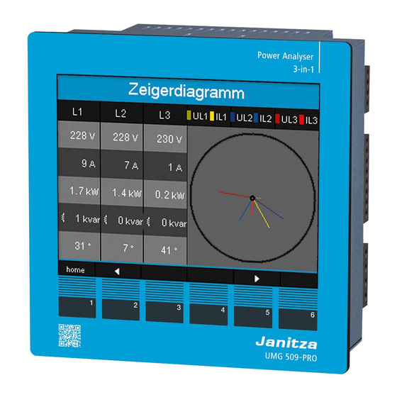
Page 75: Phasor Diagram Examples
UMG 509-PRO 12.5.1 Phasor diagram examples 12.6 Residual current Here you can see two examples of a display of Only connect residual current transformers with a measured current and measured voltage in the nominal current of 30 mA to inputs I5 and I6! -
Page 76: Failure Monitoring (Rcm)
UMG 509-PRO www.janitza.com 12.7 Failure monitoring (RCM) 12.7.1 Alarm status The device enables continuous monitoring of the The bitwise coding within the alarm registers connection to the residual current transformer for (addr. 19224 for I5, 19225 for I6) makes it possible inputs I5 and I6. -
Page 77: Overrange
UMG 509-PRO 12.8 Overrange The overrange message is displayed as long as the condition is present and it cannot be acknowl- edged. The measuring range is exceeded if at least one of the four voltage or current measure- ment inputs lies outside its specified measuring range. -
Page 78: 12.11 Communication In The Bus System
Data 00hex=00dec Data bits: Data E6hex=230dec Parity: none Error check Stop bits (UMG 509-PRO): (CRC) Stop bits, external: 1 or 2 The voltage L1-N read out from address 19000 is Number formats 230 V. short 16 bit (-215 ... 215 -1) -
Page 79: 12.11.2 Profibus
UMG 509-PRO 12.11.2 Profibus Device master file The device master file, abbreviated GSD file, de- Profibus profiles scribes the Profibus properties of the UMG. The A Profibus profile contains the data to be ex- GSD file is required by the configuration program changed between a UMG and a PLC. - Page 80 Process output area of the PLC Profile number 1st byte = Profile number (0 .. 15) 2nd byte = Data to the UMG 509-PRO • • Profibus Process input area of the PLC 1st byte = Feedback of the profile number...
- Page 81 UMG 509-PRO Factory preconfigured profiles This section presents a tabular representation of the preconfigured Profibus profiles. · Profibus profile number 0 Byte Value type Values Scaling index format Voltage L1-N Float Voltage L2-N Float Voltage L3-N Float Voltage L4-N...
- Page 82 UMG 509-PRO www.janitza.com Profibus profile number 1 Byte Value type Values Scaling index format Voltage L1-N Float Voltage L2-N Float Voltage L3-N Float Voltage L2-L1 Float Voltage L3-L2 Float Voltage L1-L3 Float Current L1 Float Current L2 Float Current L3...
- Page 83 UMG 509-PRO Profibus profile number 2 Byte Value type Values Scaling index format Active energy sum L1-L3 Float Consumed active energy sum L1-L3 Float Delivered active energy sum L1-L3 Float Reactive energy sum L1-L3 Float Ind. reactive energy sum L1-L3 Float Cap.
-
Page 84: 12.12 Recording Configuration
UMG 509-PRO www.janitza.com 12.12 Recording configuration Two recording profiles are preconfigured in the factory default setting of the device. Adaptation and expansion of recordings can be done using the GridVis® software. Profile Measured value Time base Type RMS voltage 15 min. -
Page 85: 12.13 Digital Inputs/Outputs
UMG 509-PRO 12.13 Digital inputs/outputs 12.13.2 Pulse output Your device has two digital outputs and two digital The digital outputs can also be used to output inputs. pulses for counting energy consumption. To do so, a pulse of defined length is applied to the out- put after a certain, configurable amount of energy has been reached. - Page 86 UMG 509-PRO www.janitza.com Pulse length Pulse valency The pulse length applies for both pulse outputs Use the pulse valency to specify how much ener- and is set via the GridVis® software. gy (Wh or varh) should correspond to one pulse.
- Page 87 UMG 509-PRO Determining pulse valency INFORMATION 1.Set the pulse length according to the require- ments of the connected pulse receiver. With a When using the digital outputs as pulse outputs, pulse length of 30 ms, for example, the device measurement errors can occur due to residual ripple.
-
Page 88: 13. Device Homepage
UMG 509-PRO www.janitza.com 13. Device homepage Your meter has a built-in web server that has a No prior software installation is required here to: standalone homepage. You can access your mea- · Retrieve historical as well as current measured surement device via this device homepage from values. -
Page 89: Measured Values
UMG 509-PRO 13.1 Measured values The menu item "Measured values" allows you to call up both simple and detailed views of measured val- ues and visualize individual measured values. The following menu items are available: · Brief overview · Detailed measured values ·... -
Page 90: Detailed Measured Values
UMG 509-PRO www.janitza.com 13.1.2 Detailed measured values The overview gives you access to extensive information on the following points: · Voltage · Current · Power · Harmonic oscillations · Work · Peripherals (digital inputs/outputs, temperature measurements) Fig. Detailed overview of measured values... -
Page 91: Charts
UMG 509-PRO 13.1.3 Charts You can access the measured value monitor via the "Charts" item. The measured value monitor is a con- figurable display of current and historical measured values with automatic scaling. To display a graph of the measured values, drag the desired values from the list on the left side of the screen into the field in the center of the screen. -
Page 92: Events
UMG 509-PRO www.janitza.com 13.1.5 Events The "Events" item allows you to open a graphical representation of recorded events, such as overcurrent or undervoltage. More information on event recording can be found under „11.3.3 Events“. Fig. Event recording 13.1.6 Transients The "Transients" area shows the graphical representation of transients within a date list. For more details on the transient list and transients, see sections 10.7 on page 52 and 11.3.2 on page 61. -
Page 93: Power Quality
UMG 509-PRO 13.2 Power quality The "Power Quality" (PQ) area gives you the option of retrieving the PQ status with a clear overview according to common standards. Here you have access to continuous monitoring of the power quality according to: ·... - Page 94 UMG 509-PRO www.janitza.com Fig. IEC 61000-2-4 Watchdog parameters with traffic light principle - report...
- Page 95 UMG 509-PRO Fig. IEC61000-2-4 PQ indicator parameters with traffic light principle - snapshot...
-
Page 96: Apps
An example of an installable app is the Push Service. With the Push Service, measured values are sent directly from the device to a cloud or portal solution of your choice - such as the Janitza Energy Portal. Fig. Push Service... -
Page 97: Information
You can remotely control the device here by pressing the control buttons with the mouse. Fig. Operation of the UMG 509-PRO via the device homepage 13.4.3 Downloads Click on "Downloads" to access the download area of the Janitza homepage. Here you are able to down- load catalogs and operating manuals. -
Page 98: 14. Service And Maintenance
UMG 509-PRO www.janitza.com 14. Service and maintenance Prior to outbound delivery, the device is subjected 14.6 Calibration intervals to various safety tests and is marked with a seal. A recalibration by the manufacturer or an accred- If a device is opened, the safety tests must be re- ited laboratory is recommended after about 5 peated. -
Page 99: Battery
UMG 509-PRO 14.8 Battery The internal clock is powered by the supply voltage. If the supply voltage fails, the clock is supplied by the battery. The clock provides date and time information for records, min and max values and events, for example. -
Page 100: 15. Technical Data
UMG 509-PRO www.janitza.com 15. Technical data General Net weight (with attached plug-in con- approx. 1080 g nectors) Device dimensions approx. l = 144 mm, w = 144 mm, h = 75 mm Battery Type Li-Mn CR2450, 3 V (UL 1642 approval) Clock (in the temperature range of -40°C +-5 ppm (equivalent to 3 minutes per year) -
Page 101: Voltage And Current Measurement
UMG 509-PRO 15.2 Voltage and current measurement Current measurement Nominal current 5 A Resolution 0.1 mA Measuring range 0.005 .. 7 Arms Overrange (overload) from 7.5 Arms Crest factor Overvoltage category Option 230 V: 300 V CAT III Option 24 V: 300 V CAT II Rated surge voltage 4 kV... -
Page 102: Residual Current Detection
UMG 509-PRO www.janitza.com 15.3 Residual current detection Residual current measurement (RCM) Nominal current 30 mArms Measuring range 0 .. 40 mArms Operating current 100 µA Resolution 1 µA Crest factor 1.414 (relative to 40 mA) Load 4 ohms Overload for 1 s 5 A Constant overloaded 1 A... -
Page 103: Temperature Measurement Input
UMG 509-PRO 15.4 Temperature measurement input Temperature measurement input 3-wire measurement Update time 1 second Connectable sensors PT100, PT1000, KTY83, KTY84 Total load (sensor and cable) max. 4 kOhms Cable length up to 30 m not shielded; greater than 30 m shielded... -
Page 104: Digital Inputs And Outputs
UMG 509-PRO www.janitza.com 15.5 Digital inputs and outputs Digital inputs 2 digital inputs with a common ground Maximum counter frequency 20 Hz Response time (Jasic program) 200 ms Input signal applied 18 V .. 28 V DC (typically 4 mA) Input signal not applied 0 .. -
Page 105: Interfaces
UMG 509-PRO 15.6 Interfaces RS-485 interface 3-wire connection with GND, A, B Protocol Modbus RTU/Slave, Modbus RTU/Master, Modbus RTU /Gateway Transmission rate 9.6 kbps, 19.2 kbps, 38.4 kbps, 57.6 kbps, 115.2 kbps, 921.6 kbps Termination resistor can be activated via microswitch... -
Page 106: Performance Characteristics Of Functions
5 minutes: · Comparator timer · S0 meter readings · Min. / max. / average values (without date and time) · Energy values Configuration data is saved immediately. A detailed Modbus address and parameter list can be found at www.janitza.com. -
Page 107: Dimensional Drawings
UMG 509-PRO 15.8 Dimensional drawings Fig. Side view Fig. Bottom view... -
Page 108: 16. Procedure In The Event Of A Malfunction
UMG 509-PRO www.janitza.com 16. Procedure in the event of a malfunction Failure mode Cause Remedy No display External fuse for the supply voltage Replace fuse. has tripped. No current display. No measured voltage connected. Connect measured voltage. No measured current connected. - Page 109 UMG 509-PRO Failure mode Cause Remedy Active power too small The programmed current transformer Read and program the current or too great. ratio is incorrect. transformer ratio on the current transformer The current path is assigned to the Check connection and correct if wrong voltage circuit.
-
Page 110: 17. Menu Navigation Overview
UMG 509-PRO www.janitza.com 17. Menu navigation overview 17.1 Configuration menu overview Other main values Display Display Display Communication Home Voltage L-N Status (Measured value overview) Other main values (config) Configuration Language, communication, measurement, system Display, colors, enhancements Measurement Display System... -
Page 111: Overview Of Measuring Displays
UMG 509-PRO 17.2 Overview of measuring displays Main values Device names Voltage Current Active power Active energy Overview L1..L4 L1..L3 Overview (Active power) (Tariff 1, Tariff 2) Measured values (config) Configuration Voltage Residual current Reactive power Reactive energy L5, L6 Overview, (Sum power L1..L3) - Page 112 UMG 509-PRO www.janitza.com Main values Active energy Harmonics Voltage Transients Events Monthly values currents history L1 1..8 1..8 Bar chart Voltage L1 (L2, L3, L4) (9..16) (9..16) (L2, L3, L4) Apparent en- Harmonics Current ergy currents history L1 (L2, L3, L4)
- Page 113 UMG 509-PRO Main values Phasor Oscilloscope Communication diagram status Oscilloscope Oscilloscope ULN1..3 ULN1..4 Oscilloscope IL1..3 IL1..4 Fig. Schematic representation of the menu navigation for the measuring displays, part 3...
-
Page 114: 18. Connection Example
UMG 509-PRO www.janitza.com 18. Connection example PT100 DIFF 0-30 9 10 11 12 13 14 15 16 Switch RS485 Temp. Digital Digital Outputs Inputs UMG 509-PRO Hilfsenergie Strommessung 1-4 Spannungsmessung 1-4 Auxiliary Supply Current Input 1-4 Voltage Input 1-4 L/+ N/-... - Page 115 UMG 509-PRO...
- Page 116 Vor dem Polstück 6 | 35633 Lahnau Germany Tel.: +49 6441 9642-0 info@janitza.com | www.janitza.com Doc. no. 2.059.011.2.s | 10/2022 | Subject to technical alterations. The current version of the document can be found in the download area at www.janitza.com.
Need help?
Do you have a question about the UMG 509-Pro and is the answer not in the manual?
Questions and answers