
Subscribe to Our Youtube Channel
Related Manuals for janitza UMG 806-LP


Summary of Contents for janitza UMG 806-LP
- Page 1 Multifunctional Energy Analyzer UMG 806-LP User manual and technical data (from firmware version 2.0.32) Janitza electronics GmbH Vor dem Polstück 6 35633 Lahnau | Germany Support tel. +49 6441 9642-22 info@janitza.com | www.janitza.com...
- Page 2 UMG 806-LP www.janitza.com UMG 806-LP Multifunctional energy analyzer for recording energy quantities Doc. no.: 2.064.029.1.a Date: 07/2024 The German version is the original edition of the documentation.
- Page 3 Nonetheless, we wish to point out that updates of this document are not always possible at the same time as technical refinements are implemented in our products. Please see our website under www.janitza.com for the current version. Please see our website under www.janitza.com for the current version. Information about the GridVis software.
- Page 4 UMG 806-LP www.janitza.com TABLE OF CONTENTS 1. Information on the device and the user manual 1. 1 Disclaimer 1. 2 Copyright notice 1. 3 Technical changes 1. 4 About this user manual 1. 5 Defective device/disposal 2. Safety 2. 1 Display of warning notices and safety information 2.
- Page 5 UMG 806-LP 4. 6 FCC Declaration of Conformity 4. 7 Scope of delivery 4. 8 Accessories 4. 9 Transformer 4. 10 Operating concept 4. 11 GridVis network analysis software ® 4. 12 Overview of the range of functions 4. 12. 1 Configuration on the device (via 2 buttons) 4.
- Page 6 UMG 806-LP www.janitza.com 8. 7 Temperature measurement 8. 8 RS-485 interface 8. 8. 1 Shielding 8. 8. 2 Termination resistors/Termination 8. 8. 3 Bus structure (bus segment) 8. 9 Digital output 9. PC connection 9. 1 Connection to a PC 10. Operation and button functions 10.
- Page 7 UMG 806-LP 11. 2. 9 Configuring date and time 11. 2. 10 Example: Configure month 11. 3 Parameter list 12. Commissioning 12. 1 Supply voltage 12. 2 Measured voltage 12. 3 Frequency measurement 12. 4 Measured current 12. 5 Checking the phase assignment 12.
- Page 8 UMG 806-LP www.janitza.com 15. 5. 4 Password 15. 5. 5 Firmware Update 15. 6 General information 16. Service and maintenance 16. 1 Repair and calibration 16. 2 Front panel foil and display 16. 3 Service 16. 4 Device adjustment 16. 5 Clock/Battery 16.
- Page 9 UMG 806-LP...
- Page 10 Copyright notice · Online help for the network visualization software GridVis ® © 2024 - Janitza electronics GmbH - Lahnau. All rights reserved. Any reproduction, processing, distribution or other use of this informational product, in whole or in part, is prohibited.
- Page 11 · When doing so, please bear the terms for trans- portation in mind. INFORMATION Please return defective or damaged devices to Janitza electronics GmbH in accordance with the shipping instructions for air or road freight (complete with accessories). Observe special regulations for devices with built-in...
- Page 12 UMG 806-LP www.janitza.com Safety The chapter on Safety contains information which Product safety must be observed to ensure your personal safety The device reflects current engineering practice and avoid material damage. and accepted safety standards, but hazards can arise nonetheless. Display of warning notices and safety...
- Page 13 · Switch off your installation before commenc- material damage! ing work! Secure it against being switched on! · Do not use Janitza measurement devices or Check to be sure it is de-energized! Ground components for critical switching, control or and short circuit! Cover or block off adjacent...
- Page 14 UMG 806-LP www.janitza.com Electrically qualified personnel Safety instructions for handling low power current transformers To avoid bodily injury and material damage, only electrically qualified personnel are permitted to Only use double-insulated copper work on the devices and their components, mod- cables for the wiring.
- Page 15 UMG 806-LP Safety information for handling residual WARNING current transformers Risk of injury or damage to the meter due to Only use double-insulated copper improper use! cables for the wiring. Meters with residual current measurement can trig- ger warning pulses if limit values are exceeded, and these are used exclusively for monitoring residual currents or failure monitoring.
- Page 16 UMG 806-LP www.janitza.com Sécurité Le chapitre Sécurité contient des informations que Niveaux de danger vous devez respecter pour votre propre sécurité Les avertissements et les consignes de sécurité personnelle et pour éviter les dommages matériels. sont mis en évidence par un symbole d’avertis- sement.
- Page 17 Le non-respect des conditions de raccorde- · Ne touchez pas les câbles dénudés ou sans ment des appareils de mesure Janitza ou de isolation qui se trouvent sous tension ! Equi- leurs composants peut entraîner des blessures, pez les conducteurs à fils simples d’embouts des blessures mortelles ou des dommages de câble !
- Page 18 UMG 806-LP www.janitza.com Personnel électrotechnique qualifié Consignes de sécurité pour la manipu- lation des transformateurs de courant Pour éviter les dommages corporels et matériels, de faible puissance tout travail sur des appareils et leurs composants, modules, sous-ensembles, systèmes et circuits Utilisez uniquement des câbles en cu- électriques est réservé...
- Page 19 UMG 806-LP Consignes de sécurité pour la manipu- AVERTISSEMENT lation des transformateurs de courant Danger de blessure ou d’endommagement de différentiel l’appareil de mesure par une utilisation incor- Utilisez uniquement des câbles en cu- recte ! En cas de dépassement des valeurs limites, les ivre à...
- Page 20 UMG 806-LP www.janitza.com Product description Device description CAUTION The device is a multifunctional network analyzer Malfunction and damage of the device or risk of and is suitable for: injury due to improper connection. · Measurements and calculations of electrical Improperly connected devices can deliver incorrect...
- Page 21 UMG 806-LP Intended use The device is: · Only intended for use in the industrial sector for industrial applications. · Not intended for installation in vehicles! Use of the device in non-stationary equipment consti- tutes an exceptional environmental condition and is only permissible by special agreement.
- Page 22 · Connect the device and the radio/television receiver · Modularly expandable with the 806-EC1 module in different circuits. · LCD display with backlight · if necessary, contact Janitza support or a radio/tele- · Operation via 2 buttons vision technician. · Password protection Code of Federal Regulations, Title 47, Part 15, Sub- ·...
- Page 23 · Ne dépassez pas les valeurs limites indi- UMG 806-LP for use with listed ener- quées dans le manuel d’utilisation et sur la gy-monitoring current transformers plaque signalétique ! Tenez compte de cette consigne également lors du contrôle et de la...
- Page 24 ® Use the GridVis network analysis software avail- ® able at www.janitza.com to read out data for anal- ysis. To do so, connect a PC to your measurement device via the Ethernet interface. Performance characteristics of the GridVis ®...
- Page 25 UMG 806-LP 4.12 Overview of the range of functions 4.12.1 Configuration on the device (via 2 but- tons) · Password protection · Module enhancements · Current transformer primary / secondary · Voltage transformer primary / secondary · Fieldbus parameters · Digital output ·...
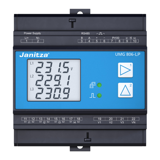
- Page 26 UMG 806-LP www.janitza.com Structure of the device Front panel and display Fig.: Front panel with display Fig.: Device front with screw terminal covers and display - 3D...
- Page 27 UMG 806-LP Item Function/Designation Supply voltage connection RS-485 interface Digital output (active energy) Temperature measurement input (PT100) Residual current measurement input I5 Module locking LED (communication) Button 1 Module communication interface Button 2 LED (pulse activity) Module locking Voltage measurement inputs V 1 , V 2 , V 3 and V N...
- Page 28 UMG 806-LP www.janitza.com Front view / side view 90 mm (3.54 in) 63.5 mm (2.5 in)
- Page 29 UMG 806-LP Identification of the device (rating plate) www.janitza.de www.janitza.de UMG 806 • 1402041 UMG 806-LP • 1402042 08/2023 • 001 08/2023 • 001 Modul 806-EC1 • 1402051 08/2023 • 001 Aux:100..300V,50/60Hz Aux:100..300V,50/60Hz 100..300V 100..300V 7VA 3W 7VA 3W MAC: 00:0E:6B:02:09:94...
- Page 30 UMG 806-LP www.janitza.com Mounting Installation location DANGER Danger of electric shock! Electric shocks lead to serious injuries, including death. · Disconnect your system from the power supply before mounting and connecting the device! · Secure it against being switched on! click! ·...
- Page 31 UMG 806-LP Grid systems Suitable grid systems and maximum rated voltag- es according to DIN EN 61010-1/A1: Three-phase 4-conductor systems Three-phase 3-conductor systems with grounded neutral conductor with grounded phase : 277 V / 480 V 480 V : 277 V / 480 V 480 V...
- Page 32 230V testing and commissioning of the Janitza mea- 50/60Hz surement device, the Janitza component and your system. AC/DC Ground- Voltage measurement ing of the system Auxiliary supply UMG 806-LP Fig. Schematic diagram, UMG 806-LP in a TN network...
- Page 33 Voltage measurement Auxiliary supply UMG 806-LP Fig. Schematic diagram, UMG 806-LP in an IT net- work without N. 230/400V 50/60Hz Impedance AC/DC Ground- ing of the system Voltage measurement Auxiliary supply UMG 806-LP Fig. Schematic diagram, UMG 806-LP in an IT network with...
- Page 34 UMG 806-LP www.janitza.com Disconnect switch ATTENTION When installing in a building, provide a suitable Material damage due to disregard of the con- disconnect switch for the supply voltage in order nection instructions! to disconnect your system and thus your device Disregard of the connection instructions or exceed- from the supply of power.
- Page 35 UMG 806-LP Voltage measurement The device has 4 voltage measurement inputs and V ) and is suitable for various con- nection variants. WARNING Risk of injury or damage to the device due to electrical voltage and improper connection! Disregard of the conditions for the connections of the voltage and current measurement inputs may damage the device or cause serious injury or death.
- Page 36 IEC 61010-1 to mains or measuring circuits. Fig. Connection example for “current measurement”. WARNING UMG 806-LP for use with listed ener- gy-monitoring current transformers Risk of injury due to electrical voltage! Severe bodily injury or death can result! Therefore...
- Page 37 UMG 806-LP AVERTISSEMENT WARNING Danger de blessure par tension électrique ! Risk of injury due to high currents and high Des blessures corporelles graves ou mortelles electrical voltages! peuvent survenir ! C’est pourquoi les consignes Severe bodily injury or death can result from: suivantes doivent être respectées :...
- Page 38 UMG 806-LP www.janitza.com 8.5.1 Measuring variants WARNING Risk of injury or damage and fire hazard to the Three-phase 4-conductor system device due to improper connection! Disregard of the conditions for the connections, e.g. connecting the voltage lines to the current mea- surement inputs, may damage the device or cause serious injury or death.
- Page 39 The measurements in medium and high voltage networks are made via current and voltage trans- formers. INFORMATION The meter is not an independent protective device against electric shock! INFORMATION Suitable for recording residual currents > 100 mA in combination with Janitza residual current transformers.
- Page 40 UMG 806-LP www.janitza.com 8.6.2 Residual current transformer example 8.6.1 Current direction of the residual current transformers Operating equipment must have reinforced or double insulation from supply circuits! For residual current measurement with current transformers in AC operation at the measuring Example:...
- Page 41 UMG 806-LP 8.6.3 Connection example - Residual current monitoring 11 12 13 14 15 16 17 18 UMG 806-LP Fig. Connection example, UMG 806-LP with residual current monitoring...
- Page 42 UMG 806-LP www.janitza.com Temperature measurement Example of temperature sensor: The device has a temperature measurement input. A temperature sensor is to measure near uninsu- The temperature is measured via terminals 7 and 8 lated power lines in a 300 V CAT III network.
- Page 43 A termination resistor must be set cates using the Modbus RTU protocol. for termination for a UMG 806-LP at the beginning or end of a bus segment, (see section "Termination For the connection capacity of the terminals, see resistors / Termination").
- Page 44 UMG 806-LP www.janitza.com 8.8.2 Termination resistors/Termination 8.8.1 Shielding Terminate the beginning and end of your bus For connections via the interfaces, use a twisted segments with termination resistors (120 Ω/0.25 W and shielded cable and observe the following for - see section "Bus structure (bus segment)”). The the shielding: ·...
- Page 45 UMG 806-LP 8.8.3 Bus structure (bus segment) · Position the client device (formerly master device) at the beginning or end of the bus structure. If the In a bus structure: client device is replaced with the bus termination · Connect all devices in line.
- Page 46 UMG 806-LP www.janitza.com Digital output ATTENTION The device has 1 digital output, which Transmission error and material damage due to · Is electrically isolated from the evaluation elec- electrical malfunction. tronics via an optocoupler. With a cable length of more than 30 m, there is an ·...
- Page 47 UMG 806-LP PC connection Connection to a PC The most common connection methods for com- DHCP server automatically assigns IP address- munication of the device with a PC (with GridVis es to the device and the PC. ® software installed) are described below.
- Page 48 - see the section Password) takes you to the configuration mode. · In configuration mode, the character appears Fig. UMG 806-LP measuring display "Voltage L1-N, L2-N and L3-N" and function buttons. on the display. To switch back to the display mode: 10.2...
- Page 49 UMG 806-LP 10.5 Overview of measuring display (display mode) The measurement device measures electrical quantities such as voltage, current, power, power factor, frequency, energy, harmonics, asymmetries or extreme values. Some of these electrical quantities can only be read out via the communication interface. More detailed information can be found in the Modbus address list.
- Page 50 UMG 806-LP www.janitza.com 10.6 Examples of basic measuring displays Phase voltage Total active power ...
- Page 51 UMG 806-LP 10.9 Max value 10.7 Examples of energy measurement Display current, forward active power, reverse active power, apparent power history max. Active energy applied EP = 30.784 kWh ...
- Page 52 UMG 806-LP www.janitza.com 11. Configuration 11.1 Configuration mode 11.2 Configuration The configuration mode is used to configure the · Press and hold buttons 1 and 2 simultaneously parameters necessary for the operation of the for 1 s to switch between the display and config- device.
- Page 53 ment input (I5). · The default setting of all current transformer ratios of the UMG 806-LP is 5 A / 333 mV (I1-I4) · Go to the 1st digit (blinking) of the primary current and 5 A/5 A (I5). value by pressing button 1.
- Page 54 UMG 806-LP www.janitza.com 11.2.4 Example: Configuring the current trans- former ratios of residual current mea- surement input I5 (700:1) · Press and hold buttons 1 and 2 simultaneously for 1 s to switch between the display and config- ...
- Page 55 Value of the The UMG 806-LP has 4 voltage measurement in- primary voltage puts (V1 - V3 and VN). Of these, you can configure (800 V) the inputs L1 (V1) to L3 (V3).
- Page 56 UMG 806-LP www.janitza.com 11.2.7 Configuring the RS-485 interface (Mod- 11.2.8 Configuring the Ethernet interface bus) INFORMATION To operate the device via the RS-485 interface (see chapter „8.8 RS-485 interface“ on page 43), The description of the Ethernet interface (mod- configure the following parameter addresses: ule 806-EC1) can be found in chapter „14.5.2...
- Page 57 11.2.9 Configuring date and time 11.2.10 Example: Configure month You can set the date and time on the UMG 806-LP · Press and hold buttons 1 and 2 simultaneously via the device display. for 1 s to switch between the display and config- You must then save the change as follows: uration modes.
- Page 58 UMG 806-LP www.janitza.com 11.3 Parameter list · Parameter addresses are not Modbus addresses! · Modbus addresses can be found in the separate Modbus address list in the download area at www.janitza.com Address Format Designation Setting range Unit Default setting uint32 Current transformer primary, I1..I3 1 ..
- Page 59 UMG 806-LP Address Format Designation Setting range Unit Default setting uint8 IP mask, xxx --- --- --- 0 .. 255 uint8 IP mask, --- xxx --- --- 0 .. 255 uint8 IP mask, --- --- xxx --- 0 .. 255 uint8 IP mask, --- --- --- xxx 0 .. 255 uint8 IP gateway, xxx --- --- --- 0 .. 255...
- Page 60 UMG 806-LP www.janitza.com 12. Commissioning INFORMATION WARNING Before commissioning, delete any production-relat- Risk of injury due to electrical voltage! ed contents of the energy meters (see section „11.3 If the device is exposed to surge voltages above Parameter list“ on page 58).
- Page 61 UMG 806-LP 12.4 Measured current 12.7 Checking measurement The device: Correctly connected voltage and current measure- · Measures current exclusively via current trans- ment inputs result in correctly calculated and dis- formers. played individual and summation power readings. · Is designed for the connection of current trans- formers with secondary currents of 333 mV.
- Page 62 UMG 806-LP www.janitza.com 12.10 Recording measured values Two recording sets are configured in the measur- ing device In the recording configuration, the measured val- ues are defined over a time interval according to the mean value and sample types: · Average type: Arithmetic mean value of the mea- sured values over the defined time interval.
- Page 63 UMG 806-LP Recording set 1 Recording set 2 The following measured values are recorded with a The following measured values are recorded with a time base of 15 minutes. time base of 1 hour: · the calculation of measured values is based on ·...
- Page 64 UMG 806-LP www.janitza.com 13. Connection example PT100 RS232 RS485 PT100 AI1+ AI2+ AI3+ AI4+ AIC Power supply RS485 Energy pulse Temperature Analog inputs UMG 806-LP Module 806-EI1 Relais outputs Current measurement Voltage measurement 11 12 15 16 17 18...
- Page 65 UMG 806-LP 14. Expansion modules The following optional expansion modules can be INFORMATION used to extend the functionality of the basic device (the basic device only supports one extension When setting up your meter and module topology, note that: module per module type): ·...
- Page 66 UMG 806-LP www.janitza.com 14.2 Installing the modules Module Install the module in switchboard cabinets or small clip fastener distribution boxes according to DIN 43880 (any mounting orientation possible) on a 35 mm (1.38") DIN rail as follows: 5. Lock the device together with the module at the top and bottom with the module clip fasteners.
- Page 67 UMG 806-LP 14.3 Front / side views 806-EC1 module 14.4 Module detection Expansion modules are detected automatically and are in active mode after detection.
- Page 68 Description Module 806-EC1 14.5.2 Configuring the Ethernet interface 14.5.1 Front LEDs and reset button INFORMATION The UMG 806-LP basic device requires the 806- (1) Operation ( EC1 module to configure an Ethernet interface RUN LED (see section „9. PC connection“ on page 47)!
- Page 69 UMG 806-LP Connection examples INFORMATION 806-EC1 module If the device is configured as a DHCP client (ad- dress 205 = 1), restart the device to obtain an IP address! UMG 806-LP Configure the parameters above as already de- scribed in section „11.2 Configuration“ on page...
- Page 70 15. EC1 module homepage 15.1 LOG IN 15.2 Overview The device’s own UMG 806-LP module homepage The homepage consists of four main parts: can be accessed via the EC1 module by calling up the IP address in a web browser. · Home...
- Page 71 UMG 806-LP Home: Start page with a brief overview of the most important measured values Measured values: Complete overview of all relevant measured values Settings Drop-down menu providing access to all setting options Information: Displays basic device information Time / Date: Displays the time and date (GMT)
- Page 72 · Active power in kilowatts · Cos-phi (unitless) · Vectorial sum value (L1..L3) of the active power and cos-phi Fig. Homepage of the UMG 806-LP with EC1 module 15.4 Measured value display In the menu bar, select "Measured values" to dis- play a complete overview of the device’s relevant...
- Page 73 UMG 806-LP Basic parameters, phase-referenced (L1, L2, L3) Voltage in volts (LL reference) (V) Voltage in volts (LN reference) (V) Active power in kilowatts (kW) Consumed active energy in kilowatt hours (kWh) Reactive power in kilovar (kvar) Reactive energy in kilovarh (kvarh)
- Page 74 Fig. Menu for settings · Password: Change the password to access the homepage · Firmware Update: Update of the firmware for the UMG 806-LP and EC1 module 15.5.1 TCP/IP · Configuration of all TCP/IP network settings for the communication between the UMG 806-LP basic device and the EC1 module.
- Page 75 EC1 must match the corresponding de- vice address of the UMG 806-LP whose values are to be displayed on the homepage. · All changes must be saved with "Save" for them to take effect. Fig. Example of Modbus settings for the UMG 806-LP device...
- Page 76 UMG 806-LP www.janitza.com 15.5.3 Current transformer (CT) / Voltage transformer (VT) ratios Configuration of all transformer ratios · Configuration options: - VT-1 (L1-L3): Entry for primary side voltage transformers L1-L3 (range 1 to 999999) - VT-2 (L1-L3): Entry for secondary side voltage...
- Page 77 UMG 806-LP 15.5.4 Password Enter and/or change password to access device settings and homepage. · Default: admin / admin · Current password: Enter the current password. · New password: Enter the new, user-defined password with a maximum of 20 characters.
- Page 78 UMG 806-LP www.janitza.com 15.5.5 Firmware Update This function can be used to update the firmware of the UMG 806-LP basic device as well as the EC1 communication module. · Select device: Selection of the device to be updated. · Select file: 1.
- Page 79 - Can be set via GridVis - Can contain user-defined additional information about the device (40 characters; ASCII 256) · Basic device firmware version (UMG 806-LP): Currently installed firmware version · Communication module firmware version (EC1): Currently installed firmware version ·...
- Page 80 UMG 806-LP www.janitza.com 16. Service and maintenance Prior to outbound delivery, the device is subjected 16.2 Front panel foil and display to various safety tests and is marked with a seal. Please note the following for the care and cleaning of the front foil and the display:...
- Page 81 UMG 806-LP 16.5 Clock/Battery WARNING The supply voltage supplies the internal clock of Risk of injury due to electrical voltage! Serious the meter. If the supply voltage fails, the battery personal injury or death may occur due to: takes over the supply of voltage to the clock. The ·...
- Page 82 UMG 806-LP www.janitza.com 16.6 Procedure in the event of a malfunction Failure mode Cause Remedy External fuse for the supply voltage has No display Replace fuse. tripped. No measured voltage connected. Connect measured voltage. No current display. No measured current connected.
- Page 83 UMG 806-LP 17. Technical information 17.1 Technical data General Net weight approx. 300 g (0.66 lb) Approx. B = 90 mm (3.54 in), H = 90 mm (3.54 in), Device dimensions D = 63.5 mm (2.5 in) Horizontal pitch 5 HP Battery Type Li-Mn CR1632, 3 V Backlight service life 45000 h (50% of the initial brightness)
- Page 84 UMG 806-LP www.janitza.com Voltage measurement 277 V LN / 480 V LL (+/-10%) acc. to IEC 3-phase 4-conductor systems with rated voltages up to 277 V LN / 480 V LL (+/-10%) acc. to UL 480 V LL (+/-10%) acc. to IEC 3-phase 3-conductor systems (grounded) with rated voltages up to 480 V LL (+/-10%) acc.
- Page 85 UMG 806-LP Digital outputs Energy pulse output Switching voltage max. 35 V DC Switching current max. 10 mA rms DC Response time approx. 500 ms Pulse width 80 ms ±20% Digital output (energy pulses) max. 10 Hz Temperature measurement Update time 1 s Total load (sensor and cable) max.
- Page 86 UMG 806-LP www.janitza.com Connecting capacity of the terminals (supply voltage) Connectible conductors. Only connect one conductor per terminal point! Single core, multi-core, fine-stranded 0.14 - 2.5 mm , AWG 26-14 Wire ferrules (non-insulated) 0.25 - 2.5 mm , AWG 23-14 Wire ferrules (insulated) 0.25 - 1.5 mm...
- Page 87 UMG 806-LP 17.2 Performance characteristics of functions Function Symbol Accuracy class Display range Norm Voltage 0-999.9 kV IEC61557-12 Current 0-99.99 kA IEC61557-12 Active power 0-9999 MW IEC61557-12 Reactive power 0-9999 Mvar IEC61557-12 Apparent power 0-9999 MVA IEC61557-12 Power factor 0-1.000 IEC61557-12 Frequency ±0.01 Hz...
- Page 88 UMG 806-LP www.janitza.com 17.3 806-EC1 module General Net weight approx. 82 g (0.18 lbs) Approx. B = 36 mm (1.42 in), H = 90 mm (3.54 in), Device dimensions D = 63.5 mm (2.5 in) Mounting orientation As desired Installation - suitable DIN rails - 35 mm (1.38") According to EN 60715...
- Page 89 UMG 806-LP NOTES...
- Page 90 Vor dem Polstück 6 | 35633 Lahnau Germany Tel. +49 6441 9642-0 info@janitza.com | www.janitza.com Doc. no. 2.064.029.1.a | Date 07/2024 | Subject to technical alterations. The current version of the document can be found in the download area at www.janitza.com.
Need help?
Do you have a question about the UMG 806-LP and is the answer not in the manual?
Questions and answers