Advertisement
Quick Links
ENGLISH
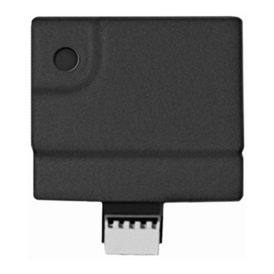
PTM: Data Storing Device
The PTM is a tiny circuit board into which the Agility panel can transmit a copy of the systemʹs configuration. The PTM stores this copy
and can also transmit the configuration information back to the Agility panel.
To transfer the system configuration from the panel to the
PTM, follow this procedure:
1. Disconnect the flat cable and remove the Agility main unit
from its wall bracket.
Note: Make sure the battery is inserted into the main unit.
2. Make sure that Dipswitch 2 is set to OFF (default setting).
3. Place the PTM onto the 5‐pin PTM connector located on the
rear of the main unit PCB. The PTM LED will turn on.
4. Press the main unit button for 5 seconds. The PTM LED
will begin to flash during the transmission of information
to the PTM.
5. Once transmission is complete, the panel will sound a
confirmation beep and the PTM LED will stop flashing and
turn on steady.
6. Disconnect the PTM from the main unit.
7. Reconnect the flat cable to the main unit and replace the
main unit in its wall bracket.
ITALIANO
PTM: Dispositivo di Trasferimento Programmazione
Il PTM è una piccola scheda elettronica che permette alla centrale Agility di trasmetterle una copia della configurazione del sistema. Il
PTM conserva questa copia e può inoltre ritrasmettere le informazioni alla centrale Agility.
Per trasferire la configurazione del sistema dal PTM alla
centrale, seguire i seguenti passaggi:
1. Scollegare il cavo piatto e rimuovere l'unità principale di
Agility dal supporto a parete.
Nota: assicurarsi che la batteria sia inserita nell'unità principale.
2. Assicurarsi che il microinterruttore 2 sia su OFF
(impostazione predefinita).
3. Posizionare il PTM sull'innesto a 5 aghi nominato PTM
collocato sul retro dell'unità centrale PCB. Il LED PTM si
accende.
4. Premere il tasto dell'unità principale per 5 secondi. Il LED
PTM lampeggia velocemente durante la trasmissione delle
informazioni al PTM.
5. Una volta che la trasmissione è stata completata, la centrale
emette un avviso sonoro e il LED PTM smette di
lampeggiare e si accende con luce fissa.
6. Rimuovere il modulo PTM dall'unità centrale.
7. Ricollegare il cavo piatto all'unità centrale e ricollocare
lʹunità centrale nel suo supporto a parete.
PTM
(Program Transfer Module)
To transfer the system configuration from the PTM to the Agility
panel, follow this procedure:
1. Disconnect the flat cable and remove the Agility main unit from its
wall bracket.
Note: Make sure the battery is inserted into the main unit.
Make sure that the Default Enable system flag is on.
2. Set Dipswitch 2 to ON.
3. Place the PTM onto the 5‐pin PTM connector located on the main
unit PCB.
4. All LEDS on the main unit will begin to flash simultaneously. The
PTM LED will begin to flash during the transmission of
information to the panel.
5. Once transmission is complete, the panel will sound a confirmation
beep.
Note: If the procedure fails the panel will make 3 short error beeps, and you
will need to do the procedure again
6. Disconnect the PTM from the main unit.
7. Reset Dipswitch 2 to OFF.
8. Reconnect the flat cable to the main unit and replace the main unit
in its wall bracket.
Per trasferire la programmazione dal PTM ad Agility, seguire questi
passaggi:
1. Scollegare il cavo piatto e rimuovere l'unità principale di Agility
dal supporto a parete.
Note: assicurarsi che la batteria sia inserita nell'unità principale.
Assicurarsi che nel menù Sistema, Controlli, Base, la voce "Abilita
Default" sia posta su SI.
2. Spostare il microinterruttore 2 su ON.
3. Posizionare il PTM sull'innesto a 5 aghi collocato sul retro
dell'unità centrale PCB.
4. Tutti i LED dell'unità centrale lampeggiano simultaneamente. Il
LED PTM lampeggia velocemente durante la trasmissione
dell'informazione alla centrale.
5. Una volta completata la trasmissione, la centrale emette un tono di
conferma.
Nota: se la procedura non andrà a buon fine la centrale emetterà 3 brevi
segnali acustici e la procedura dovrà essere ripetuta.
6. Rimuovere il modulo PTM dall'unità centrale.
7. Riportare il microinterruttore 2 su OFF.
8. Ricollegare il cavo piatto all'unità centrale e ricollocare lʹunità
centrale nel suo supporto a parete.
Advertisement

Subscribe to Our Youtube Channel
Related Manuals for Risco Agility PTM


Summary of Contents for Risco Agility PTM
- Page 1 (Program Transfer Module) ENGLISH PTM: Data Storing Device The PTM is a tiny circuit board into which the Agility panel can transmit a copy of the systemʹs configuration. The PTM stores this copy and can also transmit the configuration information back to the Agility panel. To transfer the system configuration from the panel to the To transfer the system configuration from the PTM to the Agility PTM, follow this procedure: panel, follow this procedure: 1. Disconnect the flat cable and remove the Agility main unit 1. Disconnect the flat cable and remove the Agility main unit from its from its wall bracket. wall bracket. Note: Make sure the battery is inserted into the main unit. Note: Make sure the battery is inserted into the main unit. Make sure that the Default Enable system flag is on. 2. Make sure that Dipswitch 2 is set to OFF (default setting). 2. Set Dipswitch 2 to ON. 3. Place the PTM onto the 5‐pin PTM connector located on the 3. Place the PTM onto the 5‐pin PTM connector located on the main rear of the main unit PCB. The PTM LED will turn on. unit PCB. 4. Press the main unit button for 5 seconds. The PTM LED 4. All LEDS on the main unit will begin to flash simultaneously. The will begin to flash during the transmission of information PTM LED will begin to flash during the transmission of to the PTM. information to the panel. 5. Once transmission is complete, the panel will sound a 5. Once transmission is complete, the panel will sound a confirmation confirmation beep and the PTM LED will stop flashing and beep. turn on steady. 6. Disconnect the PTM from the main unit. Note: If the procedure fails the panel will make 3 short error beeps, and you will need to do the procedure again ...
- Page 2 (serigrafiado como PTM). El LED del PTM se encenderá. 4. Todos los LEDs de la unidad principal empezarán a parpadear de 4. Presione el botón de la unidad principal durante 5 forma simultánea. El LED del PTM parpadeará rápidamente segundos. El LED del PTM parpadeará rápidamente durante la transmisión de información a la central. durante la transmisión de la información al PTM. 5. Una vez que ha terminado la transmisión, el panel emitirá un 5. Una vez finalizada la transmisión, la central emitirá un pitido de confirmación. sonido de confirmación, y el LED del PTM dejará de parpadear y se quedará encendido. Nota: Si la transferencia fallara, la central emitirá tres pitidos cortos de error, y 6. Desconecte el PTM de la unidad principal. deberá repetir el mismo procedimiento otra vez. 7. Conecte de nuevo el cable plano a la unidad principal y 6. Desconecte el PTM de la unidad principal. vuelva a colocarla en su soporte de pared. 7. Vuelva a colocar el interruptor DIP 2 en OFF. 8. Conecte de nuevo el cable plano a la unidad principal y vuelva a colocarla en su soporte de pared. All rights reserved. No part of this document may be reproduced in any form without prior written permission from the publisher. © RISCO Group 01/09 5IN1192...
Need help?
Do you have a question about the Agility PTM and is the answer not in the manual?
Questions and answers