Table of Contents
Advertisement
Advertisement
Table of Contents

Related Manuals for MSI MS-9238


Summary of Contents for MSI MS-9238
- Page 1 X2-108 Series MS-9238 1U Rackmount Server G52-92381X3...
-
Page 2: Copyright Notice
If a problem arises with your system and no solution can be obtained from the user’s manual, please contact your place of purchase or local distributor. Alternatively, please try the following help resources for further guidance. Vis i t the MSI webs ite at http ://glob al.msi. com.tw /index. php? func=faqIndex for FAQ, technical guide, BIOS updates, driver updates, and other information. -
Page 3: Safety Instructions
Safety Instructions Always read the safety instructions carefully. Keep this User’s Manual for future reference. Keep this equipment away from humidity. Lay this equipment on a reliable flat surface before setting it up. The openings on the enclosure are for air convection hence protects the equip- ment from overheating. -
Page 4: Fcc-A Radio Frequency Interference Statement
VOIR LA NOTICE D’INSTALLATION AVANT DE RACCORDER AU RESEAU. Micro-Star International MS-9238 This device complies with Part 15 of the FCC Rules. Operation is subject to the following two conditions: (1) this device may not cause harmful interference, and (2) this device must accept any interference received, including interference that may cause undesired operation. -
Page 5: Weee (Waste Electrical And Electronic Equipment) Statement
WEEE (Waste Electrical and Electronic Equipment) Statement... -
Page 8: Table Of Contents
CONTENTS Technical Support ......................ii Safety Instructions ......................iii FCC-A Radio Frequency Interference Statement ............iv W EEE (Waste Electrical and Electronic Equipment) Statement ........v Chapter 1 Getting Started ..................1-1 System Overview ....................1-2 Mainboard Specifications ................... 1-7 Mainboard Layout .................... -
Page 9: Chapter 1 Getting Started
Getting Started Chapter 1 Getting Started Thank you for choosing the X2-108 (MS-9238 v3.X), a high-performance barebone system from MSI. ® Based on the innovative Intel 5000V & ESB2E chipsets for optimal system efficiency, the X2-108 accommo- ® ® dates the latest Intel... -
Page 10: System Overview
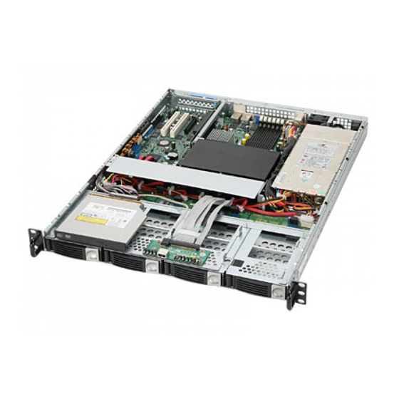
M S-9238 Server System Overview Top View X2-108 SAS Sku and X2-108A4 SATA Sku are available upon request HDD Tray Slim CD-ROM Drive Slim Floppy Disk Drive Fan Duct PCI-Express Bracket SSI EPS 1U Power Supply... -
Page 11: Front View
Getting Started Front View Front Bezel CD-ROM Drive Slim CD-ROM Drive Floppy Disk Drive Slim Floppy Disk Drive HDD Bay Swappable Hard Disk Drive Bays Port USB Port HDD Power/Status LEDs HDD Activity LED This indicator shows the activity status of the hard disk drive. It flashes when the system is accessing data on the hard disk and remains off when no disk activity is detected. - Page 12 M S-9238 Server Power LED This indicator shows the power status of the system. It glows when the main power is turned on. Status LEDs of LAN# 1/2 1. The green LED is on when there is an active connection on the LAN port. 2.
-
Page 13: Rear View
Getting Started Rear View Rear Bezel PS/2 Keyboard/Mouse Connector USB Ports Serial Port VGA Port LAN Jacks Rear Bezel LEDs Color LED State Condition RJ45 NIC1 / LAN link is not established. NIC2 Link Speed Orange On (steady state) LAN link is established. (Left Side) On (brighter &... -
Page 14: Usb Port
M S-9238 Server M ouse/Keyboard Connector Gigabit LAN Jack Link Indicator Activity Indicator Pin5 Pin6 Keyboard Clock Mouse Clock Pin4 VCC Pin3 GND SIGNAL DESCRIPTION Pin2 Pin1 Differential Pair 0+ Mouse Data Keyboard Data Differential Pair 0- Differential Pair 1+ Differential Pair 2+ Differential Pair 2- Serial Port... -
Page 15: Mainboard Specifications
Getting Started Mainboard Specifications Processor Support - Supports Intel Xeon processor 5000 series (Harpertown / W olfdale- DP / Clovertown / W oodcrest) in Socket LGA771 - Supports Intel Quad-Core / Dual-Core platforms Supported FSB - FSB 667/1066/1333MHz Chipset - Northbridge: Intel 5000V - Southbridge: Intel ESB2E M emory Support - 6 DDR2 533/667 FB-DIMM (Fully Buffered Dual-In-line DIMM) slots... - Page 16 - SSI CEB: 12” X 10.5” M ounting - 7 mounting holes System Management H8S BMC chip and MSI iConsole AP support IPMI 2.0 BMC Chip - H8S 200-pin - Host hardware interface: LPC interface - Host software interface: KCS interface...
-
Page 17: Mainboard Layout
Getting Started Mainboard Layout T: Mouse CPU1 B: Keybo ard J PWR2 J PWR1 SYSFAN1 Ports FBD13 FBD12 FBD11 FBD03 FBD02 CPU2 FBD01 LAN1 COM2 I ntel 500 0V LAN 2 Inte l 8 2563EB PCIE1 BATT I/O Chip CPUFAN1 JUSB2 CPUFAN2 BIOS... - Page 18 M S-9238 Server 1-10...
-
Page 19: Chapter 2 Hardware Setup
Mainboard Hardware CPU, Memory, Power Supply, Back Panel, Connectors, Jumpers, Slot Chassis Cover CPU, Heatsink System Assembly Memory Riser Card MS-9238 Hard Disk Drives Chassis Ears and Rails Rack Rails Rack Mounting Chassis into the Rack Chassis off the Rack... -
Page 20: Quick Components Guide
M S-9238 Server Quick Components Guide DDR2 DIMMs, p.2-4 Back Panel JPWR2, p.2-6 SYSFAN1, I/O, p.2-7 JPWR1, p.2-6 p.2-10 CPU, p.2-3 COM2, p.2-12 P C I - C l a s s Slots, p.2-15 CPUFAN1/2, p.2-10 JBIOS1, p.2-14 JUSB1/2, BIOS p.2-12 JLANDIS1/2, IDE1,... -
Page 21: Cpu (Central Processing Unit)
Hardware Setup CPU (Central Processing Unit) ® ® T his mainboard s upports the lates t Intel Xeon processor 5000 series (Harpertown/Wolfdale-DP/Clovertown/Woodcrest) in Socket LGA771. W hen you are installing the CPU, make sure that you install the cooler to prevent the CPU from overheating. -
Page 22: Memory
M S-9238 Server Memory The mainboard provides six 240-pin 533/667MHz ECC DDR2 FB-DIMM slots to sup- port the maximum of 16GB memory capacity. DDR2 240-pin, 1.8V 64x2=128 pin 56x2=112 pin Memory Population Rules FBD13 Channel 1 FBD12 FBD11 FBD03 Channel 0 FBD02 FBD01 Check the numbers of your DIMM modules and follow the population rules to install the... -
Page 23: Installing Memory Modules
Hardware Setup Installing Memory Modules 1. The memory module has only one notch on the center and will only fit in the right orientation. 2. Insert the memory module vertically into the DIMM slot. Then push it in until the golden finger on the memory module is deeply inserted in the DIMM slot. -
Page 24: Power Supply
M S-9238 Server Power Supply SSI 8-Pin CPU Power Connector: JPWR1 This connector provides 12V power output to the CPUs. SSI 24-Pin System Power Connector: JPWR2 This connector allows you to connect to an SSI power supply. To connect to the SSI power supply, make sure the plug of the power supply is inserted in the proper orientation and the pins are aligned. -
Page 25: Back Panel
Hardware Setup Back Panel M ou se USB Ports Keyboard Serial Port VGA Port M ouse/Keyboard Connector ® ® The standard PS/2 mouse/keyboard DIN connector is for a PS/2 mouse/keyboard. USB Ports The Universal Serial Bus root is for attaching USB devices such as keyboard, mouse, or other USB-compatible devices. -
Page 26: Connectors
M S-9238 Server Connectors Floppy Disk Drive Connector: FDD1 The mainboard provides a standard floppy disk drive connector. FDD1 ATA100 Hard Disk Connector: IDE1 The mainboard has a 32-bit Enhanced PCI IDE and Ultra DMA 66/100 controller that provides PIO mode 0~4, Bus Master, and Ultra DMA 66/100 function. You can connect hard disk drives, CD-ROM and other IDE devices. - Page 27 Hardware Setup Serial Attached SCSI Connector: SAS5 ~ SAS8 (Optional) The SAS connector is a new generation serial communication protocol for devices designed to allow for much higher speed data transfers. It supports data transfer speeds up to 3 Gbit/s. SAS uses serial communication instead of the parallel method found in traditional SCSI devices but still uses SCSI commands for interacting with SAS devices.
- Page 28 M S-9238 Server Chassis Intrusion Switch Connector: JCI1 This connector connects to a 2-pin chassis switch. If the chassis is opened, the switch will be short. The system will record this status and show a warning mes- sage on the screen. To clear the warning, you must enter the BIOS utility and clear the record.
- Page 29 Hardware Setup LAN LED Connectors: JACT1, JACT2 The LAN LED connectors are used to connect to LAN LEDs, which show the activity of the LAN. The JACT1 is for the LAN 1 jack and the JACT2 is for the LAN2 jack. Both LAN1 &...
- Page 30 M S-9238 Server Serial Port Connector: COM 2 The mainboard provides one 9-pin header as serial port. The port is a 16550A high speed communications port that sends/receives 16 bytes FIFOs. You can attach a serial mouse or other serial devices directly to it. Pin Definition SIGNAL DESCRIPTION...
-
Page 31: Jumpers
Hardware Setup Jumpers Clear CMOS Jumper: JBAT1 There is a CMOS RAM onboard that has a power supply from external battery to keep the data of system configuration. With the CMOS RAM, the system can automatically boot OS every time it is turned on. If you want to clear the system configuration, set the JBAT1 (Clear CMOS Jumper ) to clear data. - Page 32 M S-9238 Server BIOS Recovery Jumper: J9 Users can short connect pin#2-3 to recover the system BIOS. W hen the system is done with the job, the buzzer will beep to remind users to set the jumper to its normal state (pin#1-2 short connected).
-
Page 33: Slots
Hardware Setup Slots PCI (Peripheral Component Interconnect) Express Slot The PCI Express slot supports the PCI Express interface expansion card. The PCI Express x 8 slot supports up to 2.0 GB/s transfer rate. PCI Express x8 Slot Important When adding or removing expansion cards, make sure that you unplug the power supply first. -
Page 34: System Assembly Flowchart
M S-9238 Server System Assembly Flowchart The following flowchart shows basic system assembly procedures. Please note that always wear anti-static gloves when handling electrical components and exer- cise caution during the installation process. For more information, contact your local dealer or experienced technician. START REMOVE CHASSIS COVER INSTALL... - Page 35 Hardware Setup REPLACE RISER CARD BRACKET INSTALL HARD DISK DRIVES CONNECT HDD & POWER CORDS CHECK IF ALL PARTS ARE PROPERLY CONNECTED REPLACE CHASSIS COVER FINISH 2-17...
-
Page 36: System Assembly
M S-9238 Server System Assembly Removing the Chassis Cover 1. Unscrew the chassis cover. 2. Press the release buttons and slide the chassis cover forwards. 3. Lift up the cover and remove it from the chassis. 2-18... -
Page 37: Replacing The Chassis Cover
Hardware Setup Replacing the Chassis Cover 1. Replace the chassis cover and slide it backwards. 2. Screw to secure the chassis cover. Important Before you remove or install any components, make sure the server is not turned on or connected to the AC power. 2-19... - Page 38 M S-9238 Server CPU, Heatsink, and Fan Duct 1. On top of the CPU is a fan duct designed to enhance heat dissipation of the CPU. Lift up & remove the fan duct before installing the CPU. 2. Locate the first CPU socket. (The CPU has a plastic cap on it to protect the contact from damage.
- Page 39 Hardware Setup 6. After confirming the CPU direction (indicated be- low with red circles) for correct mating, put down the CPU in the socket housing frame. Be sure to Alignment Key grasp on the edge of the CPU base. Note that the alignment keys are matched.
- Page 40 M S-9238 Server 11. Place the heat sink on top of CPU1 and secure the screws on both sides. Note: The heat sink has to be installed to prevent the CPU from overheating. 12. Follow the same procedures to install the second heatsink. 2-22...
- Page 41 Hardware Setup Memory 1. Locate the DIMM slots on the mainboard. Insert the memory module vertically into the DIMM slot. Then push it in until the golden finger on the memory module is deeply inserted in the DIMM slot. The plastic clip at each side of the DIMM slot will automatically close.
- Page 42 M S-9238 Server M emory Population Rules FBD13 Channel 1 FBD12 FBD11 FBD03 Channel 0 FBD02 FBD01 Check the numbers of your DIMM modules and follow the population rules to install the memory. Channel 0 Channel 1 1st DIMM 2nd DIMM 3rd DIMM 1st DIMM 2nd DIMM...
-
Page 43: Expansion Card
Hardware Setup Expansion Card 1. Locate the riser card bracket and lift it up from the chassis. 2. Unscrew the cover plate and put it aside for later use. 2-25... - Page 44 M S-9238 Server 3. Insert the expansion card into the PCI-Express slot on the riser card. 4. Screw to secure the expansion card bracket. 5. Place the riser card bracket on top of the PCI-Express slot on the motherboard. Align the riser card golden fingers with the PCI-Express slot. 6.
-
Page 45: Hard Disk Drive
Hardware Setup Hard Disk Drive 1. To release the hot-swapping HDD tray, flip open the tray lever and pull the tray out of the bay. 2. At the rear of the HDD are four screw holes, two on the right and two on the left side. - Page 46 M S-9238 Server 3. Insert the HDD tray into the bay and push the tray lever back in place. 2-28...
-
Page 47: Rack Mounting
Hardware Setup Rack Mounting 1. Pull the inner channel out. latch Press the latch to disconnect. 2. Assemble the inner rail to the chassis. Fasten 6 screws at least to attach the inner channel onto the chassis. M4 screw 2-29... - Page 48 M S-9238 Server 3. Mount the L-shaped bracket onto the outer channel. BACK washer black screw FRONT U se b l a ck rou n d head screws. shall be in flush position 4. Mount the slides to the vertical racks. Type A Type B M5 screw...
- Page 49 Hardware Setup 5. Insert the chassis into the frame. 2-31...
- Page 50 M S-9238 Server 2-32...
-
Page 51: Chapter 3 Bios Setup
BIOS Setup Chapter 3 BIOS Setup This chapter provides information on the BIOS Setup program and allows you to configure the system for optimum use. You may need to run the Setup program when: ² An error message appears on the screen during the system booting up, and requests you to run SETUP. -
Page 52: Entering Setup
M S-9238 Server Entering Setup Power on the computer and the system will start POST (Power On Self Test) process. W hen the message below appears on the screen, press <F2> key to enter Setup. Press <F2> to enter SETUP If the message disappears before you respond and you still wish to enter Setup, restart the system by turning it OFF and On or pressing the RESET button. -
Page 53: Control Keys
BIOS Setup Control Keys Select Items Select Menus Select Sub-menus Enter Exit Change Values Help Setup Defaults <F9> Save and Exit <F10> Getting Help After entering the Setup menu, the first menu you will see is the Main Menu. M ain M enu The main menu lists the setup functions you can make changes to. -
Page 54: The Menu Bar
M S-9238 Server The Menu Bar Main Use this menu for basic system configurations, such as time, date etc. Advanced Use this menu to set up the items of special enhanced features available on your system’s chipset. Security Use this menu to set Supervisor and User Passwords. Power Use this menu to specify your settings for power management. -
Page 55: Main
BIOS Setup Main System Time (hh:mm:ss) The time format is <Hour> <Minute> <Second>. System Date (mm:dd:yy) The date format is <Month> <Date> <Year>. Legacy Diskette A This setting allows you to set the type of floppy drives installed. IDE Channel 0 Master/Slave, SATA Port 1/2/3/4 [Type] Press <+>... - Page 56 M S-9238 Server [32-Bit I/O] Enables 32-bit communication between CPU and IDE card [Tranfer Mode] Selects the method for transferring the data between the hard disk and system memory [Ultra DMA Mode] Indicates the type of Ultra DMA Boot Features The sub-menu is used to configure system boot-up features.
- Page 57 BIOS Setup System Information Press <Enter> to view the hardware specifications of your system. System M emory, Extended M emory These items show the memory status of the system. (Read-only)
-
Page 58: Advanced
M S-9238 Server Advanced Reset Configuration Data Select [Yes] if you want to clear the Extended System configuration Data (ESCD) area. Large Disk Access M ode Defaulting this setting to [DOS] will create a Translated FDPT. Compatible ill-behaved applications will operate correctly when [DOS] is selected. Setting to [Other] will create a Standard FDPT. - Page 59 BIOS Setup Advanced Chipset Control USB Host Controller This setting disables/enables the onboard USB host controller. IOAT Support This field enables Intel I/O Acceleration Technology which transfers data more efficiently. ECC Function Support This setting supports Single bit / None ECC (Error Correction Code) checking, a method of checking the integrity of data in DRAM.
- Page 60 M S-9238 Server [Enhanced] SATA and PATA drives are auto-detected and placed (non-AHCI) in Native IDE mode. SATA RAID & AHCI Enable (for Adaptec SATA RAID Option ROM) If this setting is set to [Enabled] and the SATA RAID function is not configured, only AHCI mode will be supported.
- Page 61 BIOS Setup Advanced Processor Options Intel Virtualization Technology Virtualization enhanced by Intel Virtualization Technology will allow a platform to run multiple operating systems and applications in independent partitions. With virtualization, one computer system can function as multiple “virtual” systems. Thermal M anagement 2 (auto detect function) ®...
- Page 62 M S-9238 Server I/O Device Configuration Serial Port A/B This is used to enable or disable the onboard serial port A/B. Base I/O Address These items specify the base I/O addresses of the onboard serial port A/B. Interrupt These field allows you to select IRQ Resources for serial port A/B. Floppy Disk Controller Select [Enabled] if your system has a floppy disk controller (FDC) installed on the system board and you wish to use it.
- Page 63 BIOS Setup Onboard Device Control LAN Option ROM Scan Use this feature to initialize device expansion ROM. Onboard SAS This setting allows you to enable/disable the onboard SAS device. 3-13...
- Page 64 M S-9238 Server Console Redirection Com Port Address This setting enables/disables the Com port address for console connection. Baud Rate This setting specifies the transfer rate (bits per second) of Console Redirection. Console Type This setting specifies the console type. Flow Control This feature allows you to enable flow control.
- Page 65 BIOS Setup DM I Event Logging Event log validity/capacity These items indicate the status of Event log validity and capacity. View DMI event log These item allows you to view the content of the DMI event log. Event Logging This function is used to log DMI events. Mark DM I events as read d This field allows you to mark DMI events as read.
- Page 66 M S-9238 Server IPMI IPMI Specification Version Indicate the IPMI (Intelligent Platform Management Interface) version. BM C Hardware/Firmware Version Indicate the BMC (Baseboard Management Controller) version. System Event Logging This function is used to log system events. Clear System Event Log This function is used to clear system event logs.
- Page 67 BIOS Setup OS boot Watchdog Setting the option to [Enabled] If OS boot fails, W atchdog Timer reboots the OS. Timer for loading OS (min) This setting specifies the timer for loading OS. It will take an action depend on the setting of Time out action after time out. Time out action This setting determines what action to take if OS fails to boot.
- Page 68 M S-9238 Server Dynamic or Static IP Config This setting is used to configure your dynamic (temporary) or static (permanent) network IP. IP Address, IP Subnet Mask, Default Gateway Use these settings to set up the IP address, IP subnet mask, and default gate- way for your system network.
-
Page 69: Security
BIOS Setup Security Supervisor Password Is, User Password Is These items indicate the status of password settings. Set Supervisor Password Supervisor Password controls access to the BIOS Setup utility. Set User Password User Password controls access to the system at boot. Password on Boot Choosing [Enabled] requires a password on boot. -
Page 70: Power
M S-9238 Server Power Important S3-related functions are available only when your BIOS supports S3 sleep mode. Power Button Function This feature allows users to configure the power button function. Settings are: [Instant-Off] The power button functions as a normal power-on/-off button. - Page 71 BIOS Setup After Power Failure This setting specifies whether your system will reboot after a power failure or interrupt occurs. Available settings are: [Stay Off] Returns the system to an off state. [Power On] Returns the system to a full on state. [Last State] Restores the system to the previous status before power failure or interrupt occurred.
-
Page 72: Boot
M S-9238 Server Boot These settings allow users to set the priority of the specified devices.You may use the arrow keys ( ) to select the desired device, <+>/<-> key to move it up/down in the priority list, <x> key to exclude or include the device to boot, (Shift + 1) to enable or disable a device, (1 - 4) keys to load default boot sequence. -
Page 73: Exit
BIOS Setup Exit Exit Saving Changes Save changes to CMOS and exit setup. Exit Discarding Changes Abandon all changes and exit setup. Load Setup Defaults Use this menu to load the default values set by the BIOS vendor for stable system performance. - Page 74 M S-9238 Server 3-24...
-
Page 75: Appendix A Adaptec Sata Raid
Adaptec SATA RAID Appendix A Adaptec SATA RAID The Southbridge provides a hybrid solution that com- bines six independent SATAII ports for support of up to six Serial ATAII (Serial ATAII RAID) drives. It offers RAID level 0 (Striping), RAID level 1 (Mirroring and Duplexing) and RAID level 10 (A Stripe of Mirrors). -
Page 76: Introduction
Then toggle to “ Ins tallation ” and, at th e c omm and pr ompt, ty pe “broken_modules=ahci” 4. RAID support on Linux OS will be changed by vendors. Please contact MSI Sales if you need SATA RAID support on Linux OS. -
Page 77: Bios Configuration
Adaptec SATA RAID BIOS Configuration The Adaptec SATA Option ROM should be integrated with the system BIOS on all motherboards with a supported Intel chipset. The Adaptec Option ROM is the Adaptec RAID implementation and provides BIOS and DOS disk services. Please use <Ctrl> + <A>... - Page 78 M S-9238 Server After pressing the <Ctrl> and <A> keys simultaneously, the following window will appear: (1) Create RAID Volume Enter Array Configuration Utility. Select option “Create array” and press <Enter> key. The following screen appears.
- Page 79 Adaptec SATA RAID Then in the Select drivers to create Array field, specify the devices and then press the <Enter> key to go to the next field. Use the arrow keys to select the RAID level best suited to your usage model in RAID Level.
- Page 80 M S-9238 Server Then Enter the Array Label name, and pressing the <Enter> key to select and advance to the next field. The available values range from 16KB to 64 KB in power of 2 increments. The strip value should be chosen based on the planned drive usage.
- Page 81 Adaptec SATA RAID Enter Manager Arrays to confirm if the creation is finished.
- Page 82 M S-9238 Server (2) Delete RAID Volume Here you can delete the RAID volume, but please be noted that all data on RAID drives will be lost. Important If your system currently boots to RAID and you delete the RAID volume in the Adaptec RAID Option ROM, your system will become unbootable.
- Page 83 Adaptec SATA RAID Select [Delete], and press <Enter>. The following screen appears: Press <Y> key to accept the volume deletion.
- Page 84 M S-9238 Server A-10...
-
Page 85: Appendix Blsi Sas Raid
LSI SAS RAID Appendix B LSI SAS RAID This appendix explains how to configure and use the components of the LSI Logic Integrated RAID (IR) soft- ware with LSI SAS 106 4/1 064E & 1068 /106 8E controllers. -
Page 86: Introduction To Integrated Raid
M S-9238 Server 1. Introduction to Integrated RAID This section provides an overview of the LSI Logic Integrated RAID solution for LSI Logic SAS controllers, its features, and its benefits. The LSI Logic Integrated RAID solution provides cost benefits for the server or workstation market where the extra performance, storage capacity, and/or redun- dancy of a RAID configuration are required. -
Page 87: Integrated Mirroring Overview
LSI SAS RAID 2. Integrated Mirroring Overview This section provides an overview of the LSI Logic Integrated Mirroring (IM) feature. 2.1 Introduction As a result of the shift towards Network Attached Storage (NAS), ISPs need a cost effective, fault-tolerant solution to protect the operating systems on small form factor, high-density, rack-mountable servers. - Page 88 M S-9238 Server 2.2 IM Features LSI Logic Integrated Mirroring and Integrated Mirroring Enhanced support the follow- ing features: Configurations of one or two IM or IME volumes on the same LSI Logic SAS controller. Each volume can consist of two mirrored disks (IM) or three to eight mirrored disks (IME).
- Page 89 LSI SAS RAID 2.3 IM/IME Description The LSI Logic Integrated Mirroring (IM) feature supports one or two mirrored volumes on each LSI Logic SAS controller (or one mirrored volume and one Integrated Striping volume). Typically, one of these volumes is the boot volume, as shown in Figure 2.1. This is accomplished through the firmware of the LSI Logic SAS controller that supports the standard Fusion-MPT interface.
- Page 90 M S-9238 Server An IME volume can be configured with up to eight mirrored disks, or seven mirrored disks and a global hot spare. Figure 2.3 shows the logical view and physical view of an Integrated Mirroring Enhanced (IME) volume with three mirrored disks. Each mir- rored stripe is written to a disk and mirrored to an adjacent disk.
-
Page 91: Integrated Mirroring Firmware
LSI SAS RAID 2.4 Integrated Mirroring Firmware This section describes features of the LSI Logic Integrated Mirroring (IM) firmware, which supports up to two IM volumes per LSI Logic SAS controller. 2.4.1 Host Interface The IM host interface uses the Message Passing Interface, as described in the Fusion-MPT Message Passing Interface Specification. - Page 92 M S-9238 Server disk. The IM firmware then resynchronizes the mirrored data. The IM firmware is automatically notified when the failed disk has been replaced, and the firm- ware then designates that disk as the new hot spare. 2.4.7 M edia Verification The IM firmware supports a background media verification feature that runs at regular intervals when the IM/IME volume is in optimal mode.
-
Page 93: Creating Integrated Mirroring Volumes
LSI SAS RAID 3. Creating Integrated Mirroring Volumes This section describes how to create Integrated Mirroring (IM) and Integrated Mirror- ing Enhanced (IME) volumes using the LSI Logic SAS BIOS Configuration Utility (SAS BIOS CU). 3.1 IM Configuration Overview You can use the SAS BIOS CU to create one or two IM or IME volumes on each LSI Logic SAS controller, with an optional global hot spare disk. - Page 94 M S-9238 Server is available. So adding a global hot spare greatly increases the level of data protection. (One global hot spare is allowed for the one or two volumes config ured on a controller.) 3.2.1 Creating an IM Volume Follow these steps to create an IM volume with the SAS BIOS CU: 1.
- Page 95 LSI SAS RAID Figure 3.2 shows an IM volume configured with a global hot spare disk. 8. W hen the volume has been fully configured, press C and then select Save changes then exit this menu to commit the changes. The SAS BIOS CU pauses while the array is being created.
-
Page 96: Creating A Second Im Or Ime Volume
M S-9238 Server 3.3 Creating a Second IM or IME Volume The LSI Logic SAS controllers allow you to configure two IM or IME volumes. If one volume is already configured, and if there are available disk drives, there are two ways to add a second volume. -
Page 97: Managing Hot Spares
LSI SAS RAID 3.4 Managing Hot Spares You can create one global hot spare disk to protect the one or two IM/IME volumes defined on a SAS controller. Usually, you create the global hot spare at the same time you create the IM/IME volume. Follow these steps to add a global hot spare disk later for the existing IM/IME volumes on the controller: 1. -
Page 98: Other Configuration Tasks
M S-9238 Server 3.5 Other Configuration Tasks This section explains how to do other tasks related to configuring and maintaining IM and IME volumes. 3.5.1 Viewing Volume Properties Follow these steps to view the properties of volumes: 1. In the SAS BIOS CU, select an adapter from the Adapter List. Select the RAID Properties option. - Page 99 LSI SAS RAID Follow these steps to delete a selected array: 1. Select Delete Array on the Manage Array screen. 2. Press Y to delete the array. After a pause, the firmware deletes the array. If there is another remaining array and a global hot spare disk, the firmware checks the hot spare disk to determine if it is compatible with the remaining array.
-
Page 100: Integrated Striping Overview
M S-9238 Server 4. Integrated Striping Overview This section provides an overview of the LSI Logic Integrated Striping (IS) feature. 4.1 Introduction The LSI Logic Integrated Striping (IS) feature is useful for applications that require the faster performance and increased storage capacity of striping. The low-cost IS feature has many of the advantages of a more expensive RAID striping solution. - Page 101 LSI SAS RAID 4.3 IS Description The IS feature writes data across multiple disks instead of onto one disk. This is accomplished by partitioning each disk’s storage space into 64 Kbyte stripes. These stripes are interleaved round-robin, so that the combined storage space is composed alternately of stripes from each disk.
-
Page 102: Integrated Striping Firmware
M S-9238 Server 4.4 Integrated Striping Firmware This section describes features of the LSI Logic Integrated Striping (IS) firmware. 4.4.1 Host Interface The IS host interface uses the Message Passing Interface, as described in the Fusion-MPT Message Passing Interface Specification, including Integrated Striping. -
Page 103: Creating Integrated Striping Volumes
LSI SAS RAID 5. Creating Integrated Striping Volumes This section describes how to create Integrated Striping (IS) volumes using the LSI Logic SAS BIOS Configuration Utility (SAS BIOS CU). 5.1 IS Configuration Overview You can use the SAS BIOS CU to create multiple IS volumes, with up to 10 drives total on an LSI Logic SAS controller. - Page 104 M S-9238 Server 2. Press Enter to go to the Adapter Properties screen, shown in Figure 5.1. 3. On the Adapter Properties screen, use the arrow keys to select RAID Proper- ties on the screen and press Enter. 4. W hen you are prompted to select a volume type, select Create IS Volume. The Create New Array screen shows a list of disks that can be added to a volume.
-
Page 105: Creating A Second Is Volume
LSI SAS RAID Figure 5.2 shows an IS volume configured with two drives. 6. W hen the volume has been fully configured, press C and then select Save changes then exit this menu to commit the changes. The configuration utility will pause while the array is being created. Note: Integrated Striping does not provide any data protection in the event of disk failure. - Page 106 M S-9238 Server 3. On the Adapter Properties screen, use the arrow keys to select RAID Proper- ties and press Enter. 4. Continue with step 4 of the IS creation procedure in the previous section to create a second volume. 5.4 Other Configuration Tasks This section explains how to do other tasks related to configuring and maintaining IS volumes.
- Page 107 LSI SAS RAID have finished creating the volume. You can locate individual disk drives from the SAS Topology screen. To do this, move the cursor to the name of the disk in the Device Identifier column and press Enter. The LED on the disk flashes until the next key is pressed. You can locate all the disk drives in a volume by selecting the volume on the RAID Properties screen.
Need help?
Do you have a question about the MS-9238 and is the answer not in the manual?
Questions and answers