Table of Contents
Advertisement
Quick Links
Advertisement
Table of Contents

Related Manuals for MSI MS-9249


Summary of Contents for MSI MS-9249
- Page 1 P1-102A2M MS - 9249 1U Rackmount Server User’ s Guide G52-S9249X1...
- Page 2 VOIR LA NOTICE D’ INSTALLATION AVANT DE RACCORDER AU RESEAU. Micro-Star International MS-9249 This device complies with Part 15 of the FCC Rules. Operation is subject to the following two conditions: (1) this device may not cause harmful interference, and (2) this device must accept any interference received, including interference that may cause undesired operation.
-
Page 3: Copyright Notice
Alternatively, please try the following help resources for further guidance. Visit the MSI website for FAQ, technical guide, BIOS updates, driver updates, and other information: http://www.msi.com.tw/ Contact our technical staff at: support@msi.com.tw... -
Page 4: Safety Instructions
Safety Instructions Always read the safety instructions carefully. Keep this User’s Manual for future reference. Keep this equipment away from humidity. Lay this equipment on a reliable flat surface before setting it up. The openings on the enclosure are for air convection hence protects the equipment from overheating. -
Page 5: Table Of Contents
Safety Instructions .................. iv Chapter 1. Getting Started ..............1-1 Mainboard Specifications ..............1-2 Mainboard Layout ................1-5 MSI Special Features ................ 1-6 PC Alert™ III ................1-6 LCD Front Panel Control ..............1-7 System Configuration ..............1-16 Front View ................1-16 Rear View ................ - Page 6 Connectors, Jumpers & Slots ............2-7 Hard Disk Connectors: IDE1/2 ............ 2-7 SATA Connectors Supported by ICH-HR: SATA1 & SATA2 ..2-8 Chassis Intrusion Switch Connector: JCI1 ........2-9 ISA Bridge Control Connector: JISA1 (Optional) ......2-9 Fan Power Connectors: SYSFAN2/3..........2-9 LCD Panel Connector: JLCD1 (Optional) ........
- Page 7 IPMI V1.5 BIOS Features ..............3-8 Advanced BIOS Features ............... 3-10 Advanced Chipset Features ............3-15 Integrated Peripherals ..............3-17 Power Management Setup .............. 3-22 PnP/PCI Configurations ..............3-24 PC Health Status ................3-26 Frequency/Voltage Control ............. 3-27 Load Fail-Safe/Optimized Defaults ........... 3-28 Set Supervisor/User Password ............
-
Page 8: Chapter 1. Getting Started
Getting Started Chap t er 1 . Ge tting Started Getting Started Congratulations on your purchase of the MS-9249 1U Rackmount Server. This high-performance barebone system ® ® supports the powerful Intel Pentium 4 processor and the industry-leading hardwares and provides the most efficient... -
Page 9: Mainboard Specifications
† Intel 82547GI Gigabit LAN † Intel 82541GI Gigabit LAN † Programmed Ethernet MAC address and EEPROM MSI Server Management: (Optional) † mBMC and MSI iConsole support IPMI 1.5 Onboard I/O † On-Board Peripherals include: - 1 x PS/2 Keyboard/Mouse Port - 1 serial port &... - Page 10 Getting Started Onboard IDE † 2 IDE connector to support ATA 100/66/33 Onboard SATA † 2 SATA connectors to support RAID 0, RAID 1 BIOS † PCI 2.2 compliant, VPD and DMI † PnP 1.0A, SMBIOS 2.3, ACPI 2.0 † Supports PXE boot protocol †...
- Page 11 MS-9249 1U Rackmount Server † EMC † CE Board Size † ATX compatible form factor with 9 mounting holes Devices † 2 3.5” IDE or SATA HDD cages † 1 Slim CD-ROM drive (optional) † 1 6x2 LCD Display Panel Power Supply †...
-
Page 12: Mainboard Layout
Getting Started Mainboard Layout SYSFAN1 Top : mouse Bottom: keyboard JPWR1 JIPMB1 USB ports CPUFAN1 Top : LPT Bottom: COM A VGA port RJ45 LAN jack Intel Canterwood-ES Chipsets RJ45 LAN jack Intel 82547GI SYSFAN2 SYSFAN3 PCIX1 Intel 82541GI SYSFAN4 SYSFAN5 SATA2 BIOS... -
Page 13: Msi Special Features
MS-9249 1U Rackmount Server MSI Special Features PC Alert™ III The PC Alert III is a utility you can find in the CD-ROM disk. The utility is just like your PC doctor that can detect the following PC hardware status during real time operation: ö... -
Page 14: Lcd Front Panel Control
Getting Started LCD Front Panel Control Installing the LCD Control Service Version: V2.2 OS supported: Windows NT 4 with Service Pack 4 or latest version Windows 2000, Windows XP Step 1: Insert the installation CD into the CD-ROM drive. Browse to the CD- ROM drive and double-click the executable file “setup.exe”... - Page 15 MS-9249 1U Rackmount Server Step 4: Setup has finished installing the LCD Control service on your computer. Click Install service to enable the LCD Control service. Step 5: Click OK to continue. You can restart the computer now.
- Page 16 Getting Started Un-installing the LCD Control Service Step 1: Click Start, and then point to Programs. Under Programs, Click LCD Control Panel and the following screen will pop up. Click Remove service to disable the LCD Control service. Step 2: Click OK to continue. Step 3: Under Control Panel, click Add/Remove Programs.
-
Page 17: Lcd Function Menu
MS-9249 1U Rackmount Server LCD Function Menu Here shows the LCD Front Panel and its three control buttons. Enter Next Go to the previous selection. Enter Execute the command. Next Go to the next selection. After you have installed the LCD Control Panel Service, you can simply use the LCD Front Panel Control buttons to get access to the information under LCD Info, H/W Monitor and System Conf menus. -
Page 18: Getting Started
Getting Started Host name Set Date Da te T ime Set Time Size Memory Usage Available Size Disk C Usage Available Size Hard Disk Usage Disk D Informa tion Available Size Disk E Usage Available System Conf Size Usage Disk F Available Net Mask LAN1... - Page 19 MS-9249 1U Rackmount Server Before Boot to OS (Debug Function) Function Description LCD Panel v1.1Show product information and version Initialize OK BIOS POST: C1 If the system has memory issues, it will stop at C1. Msg: Mem Sizing BIOS POST: C3 If the system has BIOS issues, it will stop at C3.
- Page 20 Getting Started LCD Info Function Description Firmware Show LCD Firmware version V1.1 Mode Show LCD working mode Communication Build date Show LCD Firmware build date 2002/03/25 Baud Rate Show LCD communication speed with COM port 9600 For PC and LCD link Character Show LCD characters 16X2...
- Page 21 MS-9249 1U Rackmount Server System Conf Function Description Host name Show system’s host name Date Set Date 1/1 Show the date and allow to set the date 2002.8.21 Time Set Time 1.1 Show the time and allow to set the time...
- Page 22 Getting Started System Conf (continued) Function Description Available 3/3 Unable to show the available size Disk F 4/4 Size 1/3 Show this partition’s size Usage 2/3 Unable to show the used size Available 3/3 Unable to show the available size LAN1 IP 1/4 Show the system IP information...
-
Page 23: System Configuration
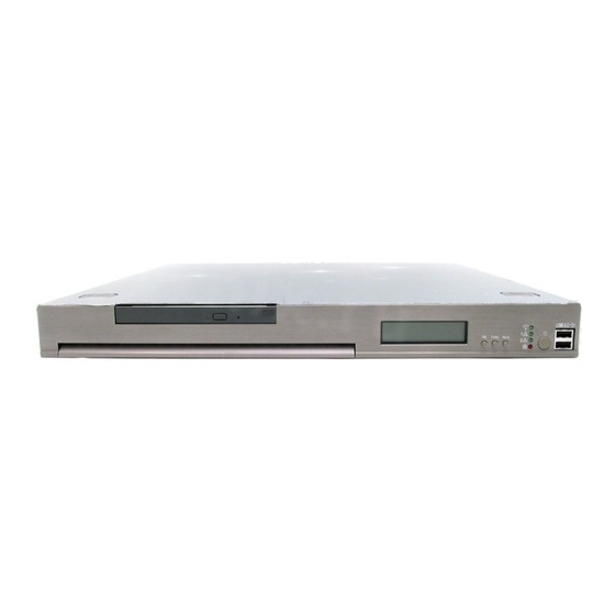
MS-9249 1U Rackmount Server System Configuration This section shows the configuration of the MS-9249 from different angles, and the connectors and buttons on the front and back panel. Front View after enlargement LCD Front Panel Slim CD-ROM Drive LED Indicators... - Page 24 Getting Started Power Button This main power button is used to turn on or off the system. Power Indicator This indicator shows the power status of the system. It glows when the main power is turned on. LAN Status Indicators These two LED indicators flash to show the activity status on LAN1 and LAN2.
-
Page 25: Rear View
MS-9249 1U Rackmount Server Rear View PS/2 Keyboard Connector PS/2 Mouse Connector USB Ports 1 & 2 Parallel Port Serial Port VGA Port LAN Jacks 1 & 2 1-18... - Page 26 Getting Started The Rear Panel provides the following connectors: KB/Mouse Connector VGA Port Pin5 Pin6 NC KB/Mouse Clock Pin4 VCC Pin3 GND VGA Connector Pin1 Pin2 NC KB/Mouse DATA (DB 15-pin) USB Ports RJ-45 LAN Jack Activity Indicator Link Indicator Gigabit LAN Pin Definition SIGNAL DESCRIPTION...
-
Page 27: Top View
MS-9249 1U Rackmount Server Top View 1U Power Supply Slim CD-ROM Drive DIMM Slots Riser Card Bracket CPU Socket Rear Fan AC Power Connector 1-20... -
Page 28: Packing Checklist
In addition, keep the box and packing materials for possible future use. Your MS-9249 1U Rackmount Server Barebone package should contain the following items: * MS-9249 1U Rackmount Server... -
Page 29: Chapter 2. Hardware Setup
Hardware Setup Chapter 2. Hardware Setup Hardware Setup This chapter provides you with the information about hard- ware setup procedures. While doing the installation, be careful in holding the components and follow the installation procedures. For some components, if you install in the wrong orientation, the components will not work properly. -
Page 30: Central Processing Unit: Cpu
MS-9249 1U Rackmount Server Central Processing Unit: CPU ® ® The mainboard supports Intel Pentium 4 Northwood / Prescott proces- sor in the 478 pin package. The mainboard uses a CPU socket called PGA478 for easy CPU installation. When you are installing the CPU, make sure the CPU has a heat sink and a cooling fan attached on the top to prevent overheating. -
Page 31: Cpu Installation Procedures For Socket 478
Hardware Setup CPU Installation Procedures for Socket 478 1. Please turn off the power and unplug the power cord before Open Lever installing the CPU. 2. Pull the lever sideways away Sliding 90 degree Plate from the socket. Make sure to raise the lever up to a 90- degree angle. -
Page 32: Memory
MS-9249 1U Rackmount Server Memory The mainboard provides four 184-pin ECC non-registered DDR266/ DDR333/DDR400 SDRAM with the maximum memory size up to 4GB. To oper- ate properly, install at least one memory module on the slot. To achieve the optimal efficiency of dual channel, install memory modules on Channel A (DIMM 1 &... -
Page 33: Installing Ddr Modules
3. The plastic clip at each side of the DIMM slot will automatically close. Volt Notch MSI Reminds You... You can barely see the golden finger if the module is properly inserted in the socket. -
Page 34: Power Supply
MS-9249 1U Rackmount Server Power Supply The mainboard supports SSI power supply for the power system. Be- fore inserting the power supply connector, always make sure that all compo- nents are installed properly to ensure that no damage will be caused. -
Page 35: Connectors, Jumpers & Slots
IDE2 (Secondary IDE Connector) IDE2 can also connect a Master and a Slave drive. MSI Reminds You... If you install two hard disks on cable, you must configure the second drive to Slave mode by setting its jumper. Refer to the hard disk documentation supplied by hard disk vendors for jumper setting instructions. -
Page 36: Sata Connectors Supported By Ich-Hr: Sata1 & Sata2
MS-9249 1U Rackmount Server SATA Connectors Supported by ICH-HR: SATA1 & SATA2 The ICH-HR chipset supports two serial IDE connectors (SATA1 & SATA2). SATA connectors are dual high-speed Serial ATA interface ports. Each supports 1 generation serial ATA data rates of 150 MB/s. All connectors are fully compliant with Serial ATA 1.0 specifications. -
Page 37: Chassis Intrusion Switch Connector: Jci1
GND. If the mainboard has a System Hardware Monitor chipset on-board, you must use a specially designed fan with speed sensor to take advantage of the CPU fan control. +12V +12V Sensor Sensor SYSFAN3 SYSFAN2 MSI Reminds You... Always consult the vendors for proper CPU cooling fan. -
Page 38: Lcd Panel Connector: Jlcd1 (Optional)
MS-9249 1U Rackmount Server LCD Panel Connector: JLCD1 (Optional) The connector is additionally provided for connection to a LCD panel, which shows information on the panel for you to identify the current status or mode of the connected system. SIGNAL... -
Page 39: Front Panel Connector: Jfp1
Hardware Setup Front Panel Connector: JFP1 The mainboard provides one front panel connector for electrical ® connection to the front panel switches and LEDs. JFP1 is compliant with Intel Front Panel I/O Connectivity Design Guide. Front USB Connector: JUSB2 The mainboard provides one USB 2.0 pin header JUSB2 that is compliant ®... -
Page 40: Enable/Disable Promise Sata Header: J2
MS-9249 1U Rackmount Server Enable/Disable PROMISE SATA Header: J2 Disable SATA IDSEL Enable SATA IDSEL (default) PCI-X Devices Header: J4 Not PCI-X Device PCI-X Device (default) PCI-X Bus Speed Header: J5 PCI-X Bus Speed is PCI-X Bus Speed is 33MHz... -
Page 41: Id Header For Bios Version: J10 & J11
Hardware Setup ID Header for BIOS Version: J10 & J11 ID1_BIOS ID2_BIOS VCC3 VCC3 Enable/Disable VGA Jumper: J8 This jumper is used to enable or disable VGA IDSEL. VGA IDSEL VGA IDSEL Disabled Enabled (default) Enable/Disable 82541 GI LAN Jumper: J1 The LAN controller integrated on the motherboard varies depending on the model you have purchased. -
Page 42: System Configure Jumper: J3
MS-9249 1U Rackmount Server System Configure Jumper: J3 The J3 jumper determines which mode the system will enter while pow- ered on. During Normal Mode, the system will enter the assigned OS as usual. During Configure Mode, the system will directly enter BIOS setup utility. This enables you to modify the BIOS configurations. -
Page 43: Pci Slot
Hardware Setup PCI Slot 64-bit PCI bus: The bus has 64 data lines and runs at 33, 66MHz. With twice data lines and much faster PCI clock, the 64-bit PCI bus increases the throughput and overall system performance. PCI-32 IRQ Routing (for ICH-HR) PCI Device INT A INT B... -
Page 45: Chapter 3. Bios Setup
BIOS Setup BIOS Setup This chapter provides information on the BIOS Setup pro- gram and allows you to configure the system for optimum use. You may need to run the Setup program when: ² An error message appears on the screen during the system booting up, and requests you to run SETUP. -
Page 46: Entering Setup
MS-9249 1U Rackmount Server Entering Setup Power on the computer and the system will start POST (Power On Self Test) process. When the message below appears on the screen, press <DEL> key to enter Setup. Press DEL to enter SETUP... -
Page 47: Getting Help
BIOS Setup Getting Help After entering the Setup menu, the first menu you will see is the Main Menu. Main Menu The main menu lists the setup functions you can make changes to. You can use the arrow keys ( to select the item. -
Page 48: The Main Menu
MS-9249 1U Rackmount Server The Main Menu Once you enter Phoenix-AwardBIOS CMOS Setup Utility, the Main Menu will appear on the screen. The Main Menu displays twelve configurable func- tions and two exit choices. Use arrow keys to move among the items and press <Enter>... - Page 49 BIOS Setup PC Health Status (for mainboard without mBMC chip) This entry shows your PC health status. Frequency/Voltage Control Use this menu to specify your settings for frequency/voltage control. Load Fail-Safe Defaults Use this menu to load the BIOS default values for minimal but stable system performance.
-
Page 50: Standard Cmos Features
MS-9249 1U Rackmount Server Standard CMOS Features The items inside Standard CMOS Features menu are divided into 10 categories. Each category includes none, one or more setup items. Use the arrow keys to highlight the item you want to modify and use the <PgUp> or <PgDn>... - Page 51 BIOS Setup your hard disk drive type is not matched or listed, you can use Manual to define your own drive type manually. If you select Manual, related information is asked to be entered to the follow- ing items. Enter the information directly from the keyboard. This information should be provided in the documentation from your hard disk vendor or the system manufacturer.
-
Page 52: Ipmi V1.5 Bios Features
MS-9249 1U Rackmount Server IPMI V1.5 BIOS Features This setup screen appears only when the mBMC chip (for Server Management) is integrated on the mainboard. PEF Configuration Status This option shows the current Platform Event Filter (PEF) configuration status. (Read only) Setting PEF Configuration This setting is used to set the Platform Event Filter (PEF) configuration. - Page 53 BIOS Setup able on expiration of the Watchdog Timer: No Action, Hard Reset, Power Down, Power Cycle. WatchDog Timer Counter This feature allows users to set the time interval to reboot the computer if a timeout event occurs. Setting options: 10 Sec, 20 Sec, 30 Sec, 40 Sec.
-
Page 54: Advanced Bios Features
MS-9249 1U Rackmount Server Advanced BIOS Features Hard Disk Boot Priority This setting determines the boot priority of the installed hard disks. Hyper-Threading Technology The Intel processor uses Hyper-Threading technology to increase transaction rates and reduces end-user response times. The technology treats the two cores inside the processor as two logical processors that can execute instruc- tions simultaneously. - Page 55 BIOS Setup Quick Power On Self Test The option speeds up Power On Self Test (POST) after you power on the computer. When setting the item to Enabled, BIOS will shorten or skip some check items during POST. Settings: Enabled, Disabled. First/Second/Third Boot Device The items allow you to set the sequence of boot devices where BIOS attempts to load the disk operating system.
- Page 56 MS-9249 1U Rackmount Server version supported by your operating system. To find out which version to use, consult the vendor of your operating system. Settings: 1.4, 1.1. Console Redirection Console Redirection operates in host systems that do not have a monitor and keyboard attached.
- Page 57 BIOS Setup View DMI Event Log Press <Enter> to view all DMI event logs. Mark DMI Events as Read Press <Enter> and a screen pops up, asking users to confirm whether or not to clear all DMI event logs immediately. Press <Y> and <Enter>, the BIOS will clear all DMI event logs right away.
- Page 58 MS-9249 1U Rackmount Server this field. With the thermal monitoring enabled, clock modulation controlled by the processor’s internal thermal sensor is also activated to keep the proces- sor within allowable temperature limit. Setting options: 4 Min, 8 Min, 16 Min, 32 Min.
-
Page 59: Advanced Chipset Features
BIOS Setup Advanced Chipset Features NOTE Change these settings only if you are familiar with the chipset. DRAM Timing Selectable Selects whether DRAM timing is controlled by the SPD (Serial Presence Detect) EEPROM on the DRAM module. Setting to By SPD enables DRAM timing to be determined automatically by BIOS based on the configurations on the SPD. - Page 60 MS-9249 1U Rackmount Server DRAM RAS# to CAS# Delay This field allows you to set the number of cycles for a timing delay between the CAS and RAS strobe signals, used when DRAM is written to, read from or refreshed. Fast speed offers faster performance while slow speed offers more stable performance.
-
Page 61: Integrated Peripherals
BIOS Setup Integrated Peripherals OnChip IDE Device Press <Enter> to enter the following sub-menu screen. IDE HDD Block Mode This allows your hard disk controller to use the fast block mode to transfer data to and from the hard disk drive. Block mode is also called block transfer, multiple commands or multiple sector read/write. - Page 62 MS-9249 1U Rackmount Server IDE DMA transfer access Setting to Enabled will open DMA bus master and execute DMA action in DOS, which will make the data transferring faster. Settings: Disabled, Enabled. On-Chip Primary/Secondary PCI IDE The integrated peripheral controller contains an IDE interface with support for two IDE channels.
- Page 63 BIOS Setup 4. Secondary Slave => Compatible Mode with Serial ATA Port 0 set to Secondary Slave 5. Logical Primary => Compatible Mode with only Serial ATA Enabled and Port 0 set to Pri- mary Master 6. Logical Secondary => Compatible Mode with only Serial ATA Enabled and Port 0 set to Sec- ondary Master 7.
- Page 64 MS-9249 1U Rackmount Server USB Keyboard/Mouse Support Select Enabled if you need to use a keyboard/mouse in the operating system. Setting options: Enabled, Disabled. CSA LAN (Giga-LAN) The field determines whether the onboard Giga-bit LAN controller is activated. Setting options: Enabled, Disabled.
- Page 65 BIOS Setup Parallel Port Mode This item selects the operating mode for the parallel port: SPP, EPP, ECP, ECP+EPP. SPP: Standard Parallel Port EPP: Enhanced Parallel Port ECP: Extended Capability Port ECP + EPP: Extended Capability Port + Enhanced Parallel Port PWRON After PWR-Fail This item specifies whether your system will reboot after a power failure or interrupt occurs.
-
Page 66: Power Management Setup
MS-9249 1U Rackmount Server Power Management Setup NOTE S3-related functions described in this section are available only when your BIOS supports S3 sleep mode. ACPI Function This item is to activate the ACPI (Advanced Configuration and Power Man- agement Interface) function. If your operating system is ACPI-aware, such as Windows 98SE/2000/ME, select Enabled. - Page 67 BIOS Setup NOTE If you have changed this setting, you must let the system boot up until it enters the operating system, before this function will work. 3-23...
-
Page 68: Pc Health Status
MS-9249 1U Rackmount Server PC Health Status This setup screen appears only when the mBMC chip (for Server Management) is not integrated on the mainboard. This section shows the status of your CPU, fan, overall system status, etc. Monitor function is available only if there is hardware monitoring mecha- nism onboard. -
Page 69: Frequency/Voltage Control
BIOS Setup Frequency/Voltage Control Use this menu to specify your settings for frequency/voltage control. Auto Detect PCI Clk This item is used to auto detect the PCI slots. When set to Enabled, the system will remove (turn off) clocks from empty PCI slots to minimize the electromagnetic interference (EMI). -
Page 70: Load Fail-Safe/Optimized Defaults
MS-9249 1U Rackmount Server Load Fail-Safe/Optimized Defaults The two options on the main menu allow users to restore all of the BIOS settings to the default Fail-Safe or Optimized values. The Optimized Defaults are the default values set by the mainboard manufacturer specifically for op- timal performance of the mainboard. -
Page 71: Set Supervisor/User Password
BIOS Setup Set Supervisor/User Password When you select this function, a message as below will appear on the screen: Type the password, up to six characters in length, and press <Enter>. The password typed now will replace any previously set password from CMOS memory. -
Page 72: Chapter 4. Chassis Installation
Chapter 3. BIOS Setup Chassis Installation This chapter provides instructions on the hardware instal- lation of the MS-9249 in two sections. System Assembly illus- trates how to assembly each component of the MS-9249. Rack Mounting describes the procedures for mounting the unit into the rack in details. -
Page 73: System Assembly Flowchart
MS-9249 1U Rackmount Server System Assembly Flowchart The following flowchart shows basic system assembly procedures. Please note that always wear anti-static gloves when handling electrical components and exercise caution during the installation process. For more information, contact your local dealer or experienced technician. - Page 74 Chassis Installation CONNECT HDD, FDD, CD-ROM CABLES & POWER CORDS REMOVE RISER CARD BRACKET INSTALL RISER CARD REPLACE RISER CARD BRACKET CHECK IF ALL PARTS ARE PROPERLY CONNECTED REPLACE CHASSIS COVER FINISH...
-
Page 75: System Assembly
MS-9249 1U Rackmount Server System Assembly Removing and Replacing Chassis Cover Locate the release buttons on the chassis cover. Press the release buttons and then push the cover backward to lift it up. To replace the cover, slide the cover forward and make sure the safety lock fits firmly. -
Page 76: Installing Cpu
Chassis Installation Installing CPU Locate the CPU socket and lift the lever up to a 90 degree angle. CPU lever up Place the CPU on top of the socket with the gold arrow pointing to the lever. gold arrow Push the lever down to secure the CPU in place. - Page 77 MS-9249 1U Rackmount Server Installing Heatsink and Fan Duct Locate the four points of the heatsink socket. Position the heatsink onto the heatsink socket carefully to avoid damaging the components around. Screw the heatsink to the chassis. Locate the screw holes as shown in...
- Page 78 Chassis Installation Screw the fan duct to the chassis. The installation of the heatsink and fan duct is now completed.
-
Page 79: Installing Memory Modules
MS-9249 1U Rackmount Server Installing Memory Modules Locate the DIMM slots on the mainboard. If a single DDR module is installed, always insert it in the first DIMM slot. To achieve the optimal efficiency of dual channel, insert the DDR modules into Channel A (Slot 1 &... -
Page 80: Installing Hdds
Chassis Installation Installing HDDs Unscrew the HDD cover plate. Turn over the HDD cover plate and remove the HDD brackets. remove HDD brackets Place the first HDD into the chassis and make sure the HDD fits with the chassis. Note: The HDD has three screw holes to fit with the chassis. - Page 81 MS-9249 1U Rackmount Server Push the HDD bracket forward to secure the HDD. Follow the same procedures to install the second HDD. Replace the HDD bracket. Replace the HDD cover plate and screw the HDD cover plate in place. 4-10...
-
Page 82: Installing Riser Card
Chassis Installation Installing Riser Card Remove the riser card bracket. Unscrew the I/O shield from the riser card bracket. Save the screw for later use. Insert the SCSI card into the bracket. Screw the SCSI card firmly to the riser card bracket. - Page 83 MS-9249 1U Rackmount Server Replace the riser card bracket. 4-12...
-
Page 84: Rack Mounting
Chassis Installation Rack Mounting Chassis Rails and Ears Screw the ears to both sides of the chassis. M4x6 black Screw the side rails to both sides of the chassis. M4x6 TIPS Attach the brackets (front and rear) onto the rails; the position of the rear bracket should be adjustable, which depends on the place where the system is installed into the rack. -
Page 85: Chassis Into The Rack
MS-9249 1U Rackmount Server Chassis into the Rack Screw the rails onto the rack. M5x8 Align the chassis rails with the rack rails, and then push the system into the rack fully Note: The chassis rails must match the rack rails well, and the ball... -
Page 86: Locking Tab
Chassis Installation Locking Tab To slide the system into the rack, first align the chassis rails with the rack rails. Then simultaneously press the locking tabs on both sides of the chassis rails and slide the system backward. The system will be locked halfway while pulling it out.
Need help?
Do you have a question about the MS-9249 and is the answer not in the manual?
Questions and answers