Table of Contents
Advertisement
Quick Links
Advertisement
Table of Contents

Subscribe to Our Youtube Channel
Related Manuals for MSI MS-9246 1U


Summary of Contents for MSI MS-9246 1U
- Page 1 MS-9246 1U Rackmount Server English Version G52-S9246X1...
-
Page 2: Fcc-A Radio Frequency Interference Statement
Manual Rev: 1.0 Release Date: July 2004 FCC-A Radio Frequency Interference Statement This equipment has been tested and found to comply with the limits for a class A digital device, pursuant to part 15 of the FCC rules. These limits are designed to provide reasonable protection against harmful interference when the equipment is operated in a commercial environment. -
Page 3: Trademarks
If a problem arises with your system and no solution can be obtained from the user’s manual, please contact your place of purchase or local distributor. Alternatively, please try the following help resources for further guidance. Visit the MSI website for FAQ, technical guide, BIOS updates, driver updates, and other information: http://www.msi.com.tw/program/service/faq/ faq/esc_faq_list.php... -
Page 4: Safety Instructions
Safety Instructions Always read the safety instructions carefully. Keep this User’s Manual for future reference. Keep this equipment away from humidity. Lay this equipment on a reliable flat surface before setting it up. The openings on the enclosure are for air convection hence protects the equip- ment from overheating. -
Page 5: Table Of Contents
Rear Bezel ....................1-10 Rear View ....................1-10 System Specifications ..................1-12 Mainboard Layout ..................... 1-16 MSI Special Features ..................1-17 PC Alert™ III ....................1-17 Chapter 2. System Hardware ................2-1 System Assembly Flowchart ................2-2 System Assembly ....................2-4 Removing the Chassis Cover .............. - Page 6 Chapter 3. Mainboard Hardware ................. 3-1 Quick Components Guide ................... 3-2 Central Processing Unit: CPU ................3-3 CPU Installation Procedures for Socket 604 ..........3-4 Memory ....................... 3-5 Memory Bus Features ................3-5 Memory Population Rules ................3-6 Installing DDR Modules ................3-7 Memory Speed/CPU FSB Support Matrix ...........
- Page 7 Appendix A: SCSI BIOS Setup (Optional) ............A-1 Entering SCSI BIOS .................... A-2 Control Keys ....................A-2 Selecting the SCSI Channel ............... A-2 Selecting the Management Type ..............A-2 Configure/View SCSI Controller Settings ............A-4 SCSI Bus Interface Definitions ..............A-4 Additional Options ..................
-
Page 8: Chapter 1. Getting Started
Getting Started Chapter 1. Getting Started Getting Started The MS-9246 1U Rackmount Server is a high-performance ® barebone system powered by dual Intel Xeon processors, Lindenhurst MCH, ICH5R/PXH PCI Bridges, and NS PC87366-ICK/VLA I/O Bridge. With high scalability, reliability, ease of use, and overall value, the MS-9246 makes an ideal choice for value conscious customers. -
Page 9: Packing Checklist
MS-9246 1U Rackmount Server Packing Checklist Unpack the package and check if all items listed below are present. If any item contained in the package is damaged or missing, please contact your local dealer for replacement. In addition, keep the box and packing materials for possible future use. Your MS-9246 1U Rackmount Server Barebone package should contain the following items: MS-9246 1U Rackmount Server... - Page 10 Getting Started Ear Set Rail Set Power Supply Options Single Power 1 + 1 Redundant Power 1 Redundant Power...
-
Page 11: System Overview
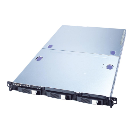
MS-9246 1U Rackmount Server System Overview This section shows the configuration of the MS-9246 from different angles, and the connectors and buttons on the front and back panel. Top View HDD Tray Slim CD-ROM Drive Slim Floppy Disk Drive Axial Fan Module (redundant) Fan Duct Memory DIMM Slots PCI Riser Card Bracket... -
Page 12: Front View
Getting Started Front View Front Bezel CD-ROM Drive Slim CD-ROM Drive Floppy Disk Drive Slim Floppy Disk Drive HDD Bay Swappable Hard Disk Drive Bays Port Serial Port USB Ports... - Page 13 MS-9246 1U Rackmount Server Power LED This indicator shows the power status of the system. It glows when the main power is turned on. HDD Activity LED This indicator shows the activity status of the hard disk drive. It flashes when the system is accessing data on the hard disk and remains off when no disk activity is detected.
-
Page 14: Getting Started
Getting Started Front Bezel LEDs Color State Description Power/Sleep Green Legacy power on/ACPI S0 state Blink (~1/sec) Sleep/ACPI S1 state Power off/ACPI S4, S5 state HDD Activity Green Blink HDD accesss activity No disk activity LAN1/LAN2 Activity Green LAN link Green Blink LAN access activity... - Page 15 MS-9246 1U Rackmount Server Diagnostic LEDs: DLED1/DLED2/DLED3/DLED4 Memory LEDs:D29/D30/D31/D32/D33/D35 Component LEDs and four Diagnostic LEDs are integrated onboard, helping users diagnose their systems. When POST or Service Processor detects an error, the corresponding LEDs light up to alert users to the condition and help service personnel identify the failing component.
- Page 16 Getting Started D-LEDs Description Processor Initialization - This will show information regarding the processor (like brand name, system bus, etc...) Testing RTC (Real Time Clock) BIOS Sign On - This will start showing information about logo, processor brand name, etc... Testing Base and Extended Memory - Testing base memory from 240K to 640K and extended memory above 1MB using various patterns.
-
Page 17: Rear Bezel
MS-9246 1U Rackmount Server Rear View Rear Bezel 5 6 7 VGA Port Gigabit LAN Jacks USB Ports Serial Port NMI Switch System ID Button System ID LED Ultra320 SCSI Connector PS/2 Keyboard/Mouse Connector (through Y-type converter) Rear Bezel LEDs Color State Description... -
Page 18: Usb Port
Getting Started Mouse/Keyboard Connector USB Port Pin5 SIGNAL Pin6 Keyboard Clock Mouse Clock -Data +Data Pin4 VCC Pin3 GND SCSI Connector Pin2 Pin1 Mouse Data Keyboard Data Serial Port SIGNAL 68-Pin Ultra320 SCSI Connector 1 2 3 4 5 Description Description SOUT +DB(12) -
Page 19: System Specifications
MS-9246 1U Rackmount Server System Specifications Mainboard MS-9146 server board ® Dual Intel Xeon (800MHz FSB) processors in 604-pin package 1MB L2 cache 6.4GB/s transmission rate Core voltage: 1.10~1.40V VTT: 1.2V Chipset MCH: Intel ® Lindenhurst (E7520) Memory Controller Hub PCI Bridge: Intel ®... - Page 20 - PFC function/SSI EPS 1U form factor/1 + 1 redundancy support - UL, cUL, TUV, CE, CB, CCC, and BSMI certified MSI Reminds You... Enabling the functionality of Hyper-Threading Technology for your computer system requires ALL of the following platform Components: ®...
- Page 21 - Integrated TMDS transmitter with support for Digital Flat Panel (DFP) monitors - Onboard 8MB Video SDRAM MSI Reminds You... Please refer to Table 1 for 2D modes supporting both CRT and LCD. The table specifies the minimum memory requirements for various display resolutions, refresh rates and color depths.
- Page 22 Getting Started MSI Server Management IPMI 1.5 (optional) MSI-9569 BMC card (with QLogic Zircon UL BMC) and MSI iConsole AP support IPMI 1.5 (option) MS-9569 BMC Card Specification BMC Chip - Qlogic Zircon UL ( ARM7 TDMI 32-bit/40MHz RISC), 128-pin PQFP...
-
Page 23: Mainboard Layout
MS-9246 1U Rackmount Server Mainboard Layout JPWR1 USB1 COM2 CPU1 KBMS1 SCSI1 JBAT1 SCSI2 DLED1 Intel NS PC87366-ICK/VLA SCSI3 FW82801ER DLED2 mP G A6 04 DLED3 Adaptec DLED4 AIC-7902W CPU2 Intel COM1 Intel Lindenhurst PCIEX1 PCI1 USB2 mP G A6 04 PCIEX2 PCI4 USB1... -
Page 24: Msi Special Features
Getting Started MSI Special Features PC Alert™ III The PC Alert III is a utility you can find in the CD-ROM disk. The utility is just like your PC doctor that can detect the following PC hardware status during real time operation: monitor CPU &... -
Page 25: Chapter 2. System Hardware
System Hardware C h a p t e r 2 . S y s t e m Hardware System Hardware This chapter provides instructions on the hardware installation of the MS-9246 in two sections. System Assembly illustrates how to assemble each component of the MS-9246. Rack Mounting de- scribes the procedures for mounting the unit into the rack in details. -
Page 26: System Assembly Flowchart
MS-9246 1U Rackmount Server System Assembly Flowchart The following flowchart shows basic system assembly procedures. Please note that always wear anti-static gloves when handling electrical components and exercise caution during the installation process. For more information, contact your local dealer or experienced technician. START REMOVE CHASSIS COVER AND FAN DUCT... - Page 27 System Hardware INSTALL RISER CARDS REPLACE RISER CARD BRACKET INSTALL HARD DISK DRIVES CONNECT HDD, FDD, CD-ROM CABLES & POWER CORDS CHECK IF ALL PARTS ARE PROPERLY CONNECTED REPLACE CHASSIS COVER FINISH...
-
Page 28: System Assembly
MS-9246 1U Rackmount Server System Assembly Removing the Chassis Cover 1. Loosen the thumbscrew on the rear bezel of the system. 2. Press the release buttons and slide the rear chassis cover backwards to remove it from the chassis. 3. Press the release buttons and slide the front chassis cover forwards to remove it from the chassis. -
Page 29: Replacing The Chassis Cover
2. Fasten the thumbscrew on the rear bezel of the system. MSI Reminds You... Before you remove or install any components, make sure the server is not turned on or connected to the AC power. -
Page 30: Cpu, Heatsink, And Fan Duct
MS-9246 1U Rackmount Server CPU, Heatsink, and Fan Duct 1. On top of the CPU is a fan duct de- signed to enhance heat dissipation of the CPU. Lift up & remove the fan duct before installing the CPU. 2. Locate the first CPU socket and raise the lever up to its full extent. CPU1 CPU2 3. -
Page 31: System Hardware
System Hardware 5. Place the heat sink on top of CPU1 and secure the screws on both sides. Note: The heat sink has to be installed to prevent the CPU from overheating. 6. Remove the dummy heatsink on socket CPU2. Follow the same procedures to install the second CPU. -
Page 32: Memory Bus Features
MS-9246 1U Rackmount Server DDR Memory 1 . L o c a t e t h e D I M M s l o t s o n t h e mainboard. Insert the DIMM memory mod- ule vertically into the DIMM slot. Then push it in until the golden finger on the memory module is deeply inserted in the socket. -
Page 33: Memory Population Rules
System Hardware Memory Population Rules The mainboard supports both single- & dual-channel modes. Install at least one DIMM module on the slots. You can install either single- or double-sided modules to meet your own needs. In dual-channel mode, make sure that you install memory modules of the same type and density on DDR DIMMs “in pairs”... -
Page 34: Pci Expansion Card
MS-9246 1U Rackmount Server PCI Expansion Card 1. Locate the riser card bracket on the chassis. A standoff guide is designed as alignment guidance for installation of the riser card bracket to avoid damage of the riser card golden fingers. Lift the bracket up from the chassis (NO screwdriver is needed). - Page 35 System Hardware 4. Install the second PCI expansion card if necessary. 5. Place the riser card bracket on top of the PCI slots on the motherboard. Align the riser card golden fingers with the PCI slots. Then aim the front end of the riser card bracket at the standoff guide and align the rear part of the bracket with the U-shaped cuts on the chassis.
-
Page 36: Pci Riser Card (Optional)
MS-9246 1U Rackmount Server PCI Riser Card (Optional) Apart from the standard PCI riser cards assembled in the system, an optional riser card is available upon request. Please refer to the following for detailed specs and the instructions on riser card installation. Standard PCI Riser Cards: MS-9583, MS-9584 MS-9583: one 64-bit/100MHz PCI-X slot (for low profile card;... -
Page 37: Scsi Hdd
System Hardware SCSI HDD 1. To release the hot-swapping HDD tray, flip open the tray lever and pull the tray out of the bay. 2. Unscrew the HDD tray and take the tray out. 2-13... - Page 38 MS-9246 1U Rackmount Server 3. At the sides of the HDD are four screw holes, two on each side. Users will find on the HDD rack four identical screw holes as on the HDD. Place the HDD into the rack and align the screw holes on the HDD with the ones on the rack.
- Page 39 System Hardware Serial ATA HDD 1. To release the hot-swapping HDD holder, unscrew it and pull it out. 2. As the system mainboard supports two Serial ATA HDDs, only the HDD trays on the right & left sides can be used. 3.
- Page 40 MS-9246 1U Rackmount Server 4. At the sides of the HDD are four screw holes, two on each side. Users will find on the HDD rack four identical screw holes as on the HDD. Place the HDD into the rack and align the screw holes on the HDD with the ones on the rack.
-
Page 41: Rack Mounting
System Hardware Rack Mounting Chassis Ears 1. Insert the chassis ear into the chassis (as marked below). 2. Push it in until it fits firmly. Screw to secure the chassis ear. 3. Follow the same procedures to install the second chassis ear. 2-17... -
Page 42: Chassis Rails
MS-9246 1U Rackmount Server Chassis Rails 1. The chassis rails and rack rails have been as- sembled together beforehand. The first thing to do with the rail set is to take the chassis rails off the rack rails. Note: The chassis rail engraved with “RIGHT SLIDE”... - Page 43 System Hardware 5. On each side of the chassis are three hooks to lock the chassis rail. First align the chassis hooks with the holes on the rail. Secure the rail to the chassis and push the rail backwards until it gets locked by the chassis hooks. Push the rail backwards until it gets locked by the chassis hooks.
-
Page 44: Rack Rails
MS-9246 1U Rackmount Server Rack Rails 1. Locate the triangle mark on the rack and install 3 screw holders to the rack as shown. 2. Align the rack rail with the rack and screw the rail to the rack by securing one screw to the bottom screw holder. -
Page 45: Cable Arm (Optional)
System Hardware Cable Arm (Optional) An optional cable arm is available to help tidy the system cables up. The cable arm attaches to the rear of the server and the system rack, allowing cables to move as the server slides back and forth within the rack cabinet. - Page 46 MS-9246 1U Rackmount Server 4. Simultaneously press down the right end of the locking mechanism and push the left end gently forwards to lock it into the hole at the end of the rack rail. The installation of the cable arm is completed at this point. Users may tidy the server cables up and tie-wrap them to the cable arm.
-
Page 47: Chassis Into The Rack
System Hardware Chassis into the Rack 1. To slide the system into the rack, first align the chassis rails with the rack rails and push the system backwards until the locking tab clicks. 2. Simultaneously press down the locking tabs on both sides of the chassis rails and push the system backwards. -
Page 48: Chassis Off The Rack
MS-9246 1U Rackmount Server Chassis off the Rack 1. To slide the system off the rack, first seize the system by its ears and gently pull the system out. 2. The system will be locked halfway while being pulled out. Simultaneously press down the locking tabs on both Press down the locking tabs sides of the chassis and pull the system... -
Page 49: Chapter 3. Mainboard Hardware
Mainboard Hardware Chapter 3. Mainboard Hardware Mainboard Hardware This chapter provides you with the information about hard- ware setup procedures. While doing the installation, be careful in holding the components and follow the installation procedures. For some components, if you install in the wrong orientation, the compo- nents will not work properly. -
Page 50: Quick Components Guide
MS-9246 1U Rackmount Server Quick Components Guide JPWR1, p.3-8 USB1, p.3-9 SCSI1/2, p.3-11 COM2, p.3-12 CN7, p.3-15 J7/J8, p.3-14 SATA1/2, p.3-10 JBAT1, p.3-13 CN3, p.3-12 CN6, p.3-14 CN4, p.3-12 Back Panel I/O, p.1-8 CPU1/2, p.3-3 mPGA604 mPGA604 PCI Express PCI-X Slots, p.3-15 x8 Slot, p.3-15 DDR DIMM1~6, p.3-5... -
Page 51: Central Processing Unit: Cpu
Heat Sink and cooling fan, contact your dealer to purchase and install them before turning on the computer. MSI Reminds You... Overheating will seriously damage the CPU and system, always make sure the cooling fan can work properly to protect the CPU from overheating. -
Page 52: Cpu Installation Procedures For Socket 604
MS-9246 1U Rackmount Server CPU Installation Procedures for Socket 604 Open Lever 1. Please turn off the power and Sliding unplug the power cord before Plate installing the CPU. 2. Pull the lever sideways away from the socket. Make sure to raise the lever up to a 170-de- Gold arrow gree angle. -
Page 53: Memory
Mainboard Hardware Memory The mainboard provides 6 slots for 184-pin DDR DIMM (Double In-Line Memory Module) modules. You can install PC2100/DDR266 or PC2700/DDR333 DDR SDRAM modules on the DDR DIMM slots (DIMM 1~6). Memory Bus Features Support for direct connect of two DDR channel interfaces, DDR266/DDR333 tech- nology Full operation support in single-channel mode on either interface Stacked or unstacked DIMM support for registered DDR266 technology(up to four... -
Page 54: Memory Population Rules
MS-9246 1U Rackmount Server Memory Population Rules The mainboard supports both single- & dual-channel modes. Install at least one DIMM module on the slots. You can install either single- or double-sided modules to meet your own needs. In dual-channel mode, make sure that you install memory modules of the same type and density on DDR DIMMs “in pairs”... -
Page 55: Installing Ddr Modules
2. Insert the DIMM memory module vertically into the DIMM slot. Then push it in until the golden finger on the memory module is deeply inserted in the socket. MSI Reminds You... You can barely see the golden finger if the module is properly inserted in the socket. -
Page 56: Power Supply
+12V +12V +12V +12V +3.3V +3.3V +3.3V -12V +3.3V 5VSB PWROK PS_ON# MSI Reminds You... 1. Power supplies of 300watt (and up) are highly recommended for sys- tem stability. 2. Please refer to the Intel/AMD websites for recommended power supplies. -
Page 57: Connectors
Mainboard Hardware Connectors The mainboard provides connectors to connect to FDD, IDE HDD, case, LAN, USB ports, CPU/system power supply fans, ... and etc. Front USB Connector: USB1 The mainboard provides one USB 2.0 pin header USB1 (optional USB 2.0 bracket available) that is compliant with Intel ®... -
Page 58: Serial Ata Raid 0, 1 Connectors: Sata1, Sata2 (Optional)
Take out the dust cover and connect to the hard disk devices Optional Serial ATA cable Connect to SATA1 or SATA2 MSI Reminds You... Please do not fold the Serial ATA cable into 90-degree angle. Otherwise, data loss may occur during transmission. 3-10... -
Page 59: Ultra320 Scsi Connectors: Scsi1/Scsi2 (Optional)
Mainboard Hardware Ultra320 SCSI Connectors: SCSI1/SCSI2 (Optional) SCSI (Small Computer System Interface) is a parallel interface standard for attaching peripheral devices to computers. Ultra320 SCSI is the seventh generation of SCSI I/O technology, and has a maximum data rate speed of 320 MB/sec. SCSI’s commitment to backward compatibility and legacy support are the primary reasons for its durability as an I/O interface, making SCSI the industry standard for disk drive connection in virtually all high-performance servers. -
Page 60: Ipmb Power Connector: Cn4
MS-9246 1U Rackmount Server IPMB Power Connector: CN4 This connector is used to connect the power supply of the IPMB (Intelligent Platform Management Bus). Pin Definition SIGNAL SMB clock SMB data PS alert 3.3RS 5-pin IPMB Connector: CN3 The mainboard provides IPMB (Intelligent Platform Management Bus) connec- tors for users to connect the BMC (Baseboard Management Controller) card. -
Page 61: Jumpers
JBAT1 Keep Data Clear Data MSI Reminds You... You can clear CMOS by shorting 2-3 pin while the system is off. Then return to 1-2 pin position. Avoid clearing the CMOS while the system is on; it will damage the mainboard. -
Page 62: Bios Recovery Jumper: Cn6
MS-9246 1U Rackmount Server BIOS Recovery Jumper: CN6 Users can short connect pin#2-3 to recover the system BIOS with a Recovery Floppy. When the system is done with the job, the buzzer will beep to remind the user to set the jumper to its normal state (pin#1-2 short connected). Normal Recovery Clear BIOS Password Jumper: J7... -
Page 63: Slots
SO DIMM (Small Outline DIMM) The SO DIMM has 144 pins and supports a full 64-bit transfer. It is specifically designed for users to install MSI’s proprietary server management tool -- MS-9569 BMC (Baseboard Management Controller) card. PCI (Peripheral Component Interconnect) Slots The motherboard provides two 64-bit PCI-X slots, one PCI Express x4 slot, and one PCI Express x8 slot. -
Page 64: Chapter 4. Bios Setup
SETUP. You want to change the default settings for customized features. MSI Reminds You... 1. The items under each BIOS category described in this chapter are under continuous update for better system performance. -
Page 65: Entering Setup
MS-9246 1U Rackmount Server Entering Setup Power on the computer and the system will start POST (Power On Self Test) process. When the message below appears on the screen, press <F2> key to enter Setup. Press F2 to enter SETUP If the message disappears before you respond and you still wish to enter Setup, restart the system by turning it OFF and On or pressing the RESET button. -
Page 66: Getting Help
BIOS Setup Getting Help After entering the Setup menu, the first menu you will see is the Main Menu. Main Menu The main menu lists the setup functions you can make changes to. You can use the arrow keys ( to select the item. -
Page 67: The Menu Bar
MS-9246 1U Rackmount Server The Menu Bar Once you enter PhoenixBIOS Setup Utility, the Main Menu will appear on the screen. On the Main Menu screen, you will see basic BIOS settings including system time & date, and the setup categories the BIOS supplies. Use Arrow keys to move among the items and menus, and make changes to the settings. - Page 68 BIOS Setup Security Use this menu to set Supervisor and User Passwords. Boot Use this menu to specify the priority of boot devices. Exit This menu allows you to load the BIOS default values or factory default settings into the BIOS and exit the BIOS setup utility with or without changes.
-
Page 69: Main
MS-9246 1U Rackmount Server Main The items inside the Main menu are for basic system information and configuration. Each item includes none, one or more setup items. Use the Up/Down arrow keys or <Tab> to highlight the item or field you want to modify and use the <+> or <->... - Page 70 BIOS Setup If you select [Manual], related information is asked to be entered to the following items. Enter the information directly from the keyboard. This information should be provided in the documentation from your hard disk vendor or the system manufacturer. [Type] Select how to define the HDD parameters [Multi-Sector Transfers]...
-
Page 71: System Summary
MS-9246 1U Rackmount Server System Summary The items inside the Main menu are for basic system information and configuration. Each item includes none, one or more setup items. Use the Up/Down arrow keys or <Tab> to highlight the item or field you want to modify and use the <+> or <->... -
Page 72: Advanced
BIOS Setup Advanced Items in the menu are divided into several sub-menus. Each sub-menu provides more settings. To enter the sub-menu, highligh the sub-menu you want to configure and press <Enter>. PhoenixBIOS Setup Utility Main System Summary Advanced IPMI Security Boot Exit Item Specific Help... - Page 73 MS-9246 1U Rackmount Server MSI Reminds You... Enabling the functionality of Hyper-Threading Technology for your computer system requires ALL of the following platform components: ® ® * CPU: An Intel Pentium 4 Processor with HT Technology; ® * Chipset: An Intel Chipset that supports HT Technology;...
- Page 74 The setting specifies whether the system will be awakened from power saving modes when activity or input signal from the specified modem is detected. Options: [Enabled], [Disabled]. MSI Reminds You... You need to install a modem card supporting power on function for “Wake On Ring” function.
- Page 75 MS-9246 1U Rackmount Server Embedded SCSI (Optional) The sub-menu is used to configure the onboard SCSI device. SCSI Controller (Optional) Use this feature to enable or disable the onboard SCSI controller. Option ROM Scan (Optional) Use this feature to initialize device expansion ROM. Embedded NIC (Gbit) The sub-menu is used to configure the onboard LAN device.
- Page 76 BIOS Setup Interrupt It specifies the interrupt for Port A/Port B. Options: [IRQ 3], [IRQ 4]. PS/2 Mouse If your system has a PS/2 mouse port and you install a serial pointing device, select [Disabled]. Legacy USB Support Set to [Enabled] if you need to use any USB 1.1/2.0 device in the operating system that does not support or have any USB 1.1/2.0 driver installed, such as DOS and SCO Unix.
- Page 77 MS-9246 1U Rackmount Server DMI Event Logging Press PgUp/<+> or PgDn/<-> to view DMI event logging. DMI Event Logging Event Log Validity: Valid Event Log Capacity: Space Available View DMI Event Log: [Enter] Event Logging: [Enabled] ECC Event Logging: [Enabled] Mark DMI Events as Read: [Enter] Clear All DMI Event Logs:...
- Page 78 BIOS Setup BIOS Redirection Port This feature selects the serial port to use for Console Redirection. [Disabled] completely disables Console Redirection. Setting options: [Disabled], [Serial Port Baud Rate It allows you to select delay befor key repeat. Options: [300], [1200], [2400], [9600], [19.2K], [38.4K], [57.6K], [115.2K].
-
Page 79: Ipmi (Optional)
MS-9246 1U Rackmount Server IPMI (Optional) This setup screen appears only when the MS-9569 BMC card (for Server Management) is installed on the mainboard. Press PgUp/<+> or PgDn/<-> to configure IPMI. PhoenixBIOS Setup Utility Main System Summary Advanced IPMI Security Boot Exit Item Specific Help... - Page 80 BIOS Setup Change COM Port Setting This setting controls the COM port setting. COM Port on BMC This setting disables/enables the COM port on BMC. System Event Logging This setting disables/enables the logging of system events. Clear System Event Log Enabling this selection will force the BIOS to clear the System Event Log on the next boot.
- Page 81 MS-9246 1U Rackmount Server System Event Log Press <Enter> to display the System Event Log. System Event Log SEL Entry Number = SEL Record ID = 0010 SEL Record Type = 02 - System Event Record Timestamp = 01.13.2004 10:50:08 Generator Id = 20 00 SEL Message Rev =...
-
Page 82: Security
BIOS Setup Security This section lets you set security passwords to control access to the system at boot time and/or when entering the BIOS setup program. It also allows you to set virus protection at hard disk boot sector. PhoenixBIOS Setup Utility Main System Summary Advanced... - Page 83 MS-9246 1U Rackmount Server Password on boot Choosing [Enabled] requires a password on boot. It requires prior setting of the supervisor password. If the supervisor password is set and this option is disabled, BIOS assumes the user is booting. Options: [Enabled], [Disabled]. Fixed disk boot sector Write protects the boot sector on the hard disk for virus protection.
-
Page 84: Boot
BIOS Setup Boot Use this menu to arrange and specify the priority of the devices from which the BIOS will attempt to boot the Operating System. PhoenixBIOS Setup Utility Main System Summary Advanced IPMI Security Boot Exit Item Specific Help CD-ROM Drive +Removable Devices +Hard Drive... -
Page 85: Exit
MS-9246 1U Rackmount Server Exit The following sections describe each of the options on this menu. Note that <Esc> does not exit this menu. You must select one of the items from the menu or menu bar to exit. PhoenixBIOS Setup Utility Main System Summary Advanced... -
Page 86: Appendix A: Scsi Bios Setup (Optional
SCSI BIOS Setup Appendix A: SCSI BIOS Setup (Optional) This chapter provides information on the Small Computer Sys- tem Interface (SCSI) BIOS setup utility and allows you to configure the SCSI subsystem for optimum use. You may need to run the SCSI BIOS setup utility when: You want to change the default SCSI controller settings for cus- tomized features. -
Page 87: Entering Scsi Bios
MS-9246 1U Rackmount Server Entering SCSI BIOS Power on the computer and the system will start POST (Power On Self Test) process. When the message below appears on the screen, press <Ctrl> + <A> keys simulta- neously to enter SCSI BIOS utility. Press <Ctrl><A>... -
Page 88: Configure/View Scsi Controller Settings
SCSI BIOS Setup AIC-7902 A at slot 0A, 03:07:00 Would you like to configure the SCSI controller, or run the SCSI Disk Utilities? Select the option and press <Enter>. Options Configure/View SCSI Controller Settings SCSI Disk Utilities Configure/View SCSI Controller Settings Use this option for SCSI controller configurations. -
Page 89: Scsi Bus Interface Definitions
MS-9246 1U Rackmount Server Configure/View SCSI Controller Settings There are 8 items in the “Configure/View SCSI Controller Settings” screen. These items display or allow you to change the SCSI controller’s settings. Use the arrow keys to highlight the item and then press <Enter> to select the value you want in each item or enter each item’s sub-menu screen. -
Page 90: Additional Options
SCSI BIOS Setup the SCSI bus is necessary. Proper termination can ensure signal on the SCSI bus will not reflect and cause data loss or errors. Settings options: [Enabled], [Disabled]. Additional Options Boot Device Configuration Press <Enter> to enter the sub-menu screen. Boot Device Configuration Single Image Master SCSI Controller ..... - Page 91 MS-9246 1U Rackmount Server SCSI Device Configuration SCSI Device ID Sync Transfer Rate (MB/Sec) ..320 320 320 320 320 320 320 320 Packetized......... Yes Yes Yes Yes Yes Yes Yes Yes QAS........... Yes Yes Yes Yes Yes Yes Yes Yes Initiate Wide Negotiation ....
- Page 92 SCSI BIOS Setup Send Start Unit Command When set to Yes, the SCSI controller sends the Start Unit command to the specified SCSI device during bootup. The interface powers up the SCSI device on-at-a-time during bootup, reducing the load on the computer’s power supply. Setting options: [Yes], [No].
-
Page 93: Bios Information
MS-9246 1U Rackmount Server POST Display Mode The field determines how much information about your SCSI controller and devices appear on the screen during bootup. For the most complete information, choose [Diagnostic]. For a faster boot, select [Silent]. Setting options: [Verbose], [Silent], [Diagnostic]. -
Page 94: Disk Utilities
SCSI BIOS Setup Disk Utilities AIC-7902 A at slot 0A, 03:07:00 Select SCSI Disk and press <Enter> SCSI ID#0: No device SCSI ID#1: No device SCSI ID#2: No device SCSI ID#3: No device SCSI ID#4: No device SCSI ID#5: No device SCSI ID#6: No device SCSI ID#7:... - Page 95 MS-9246 1U Rackmount Server Select the SCSI device which you want to manage by highlighting the item and press <Enter>. The following dialog box appears. Select the function you want to perform. SCSI ID# 0: HITACHI DK32DJ-18MW Firmware: G2G2 Capacity: 17GB Format Disk Verify Disk Media...
-
Page 96: Appendix B: Adaptec Sata Raid Utility For Intel Ich5R (Optional
1. Supports 150 MB/s transfers with CRC error checking 2. Data handling optimizations including tagged command queuing, elevator seek and packet chain command MSI Reminds You... All the information/volumes listed in your system might differ from the illustrations in this appendix. -
Page 97: Introduction
MS-9246 1U Rackmount Server Introduction 1. Overview Adaptec Embedded Serial ATA RAID with HostRAID adds RAID functionality to the Serial ATA I/O controller by supporting RAID levels 0 and 1. HostRAID adds entry level RAID support to the Serial ATA I/O controller. With HostRAID, you can add reliable performance and full data protection. - Page 98 Adaptec SATA RAID Utility for Intel ICH5R Adaptec RAID Configuration (ARC) Utility—Part of the controller’s built-in BIOS code. You start ARC by pressing Ctrl+A during BIOS startup. For details, see Adaptec RAID Configuration Utility. Array Configuration Utility (ACU)—A DOS/BIOS application used to create, configure, and manage arrays.
-
Page 99: Installing The Driver
Windows setup CD and restart the system. 5. Press F6 when prompted to install a third-party driver. MSI Reminds You... When F6 is active, a prompt appears at the bottom of the screen. Press F6 immediately — you only have 5 seconds. If you miss your chance, restart this Windows installation to complete it correctly. -
Page 100: Installing The Driver In An Existing Windows System
Adaptec SATA RAID Utility for Intel ICH5R 2. Installing the Driver in an Existing Windows System In this scenario, you are installing a driver in a system that already has a Win- dows operating system. To install the driver: 1. Create a driver disk by following the instructions from the Web site or the product CD. -
Page 101: Installing Suse Linux 8.0
MS-9246 1U Rackmount Server 4. Installing SuSE Linux 8.0 or 8.1 Installing the Driver in a New Linux System In this scenario, you are installing the driver in a new Linux system. To install the driver: 1. Obtain a driver disk from either the Web site or the product CD. 2. -
Page 102: Installing Adaptec Storage Manager - Browser Edition
Typical installation. Compact — Installs only the components required on a remotely managed system. See Managed System Components, above. MSI Reminds You... When you perform a Typical or Compact installation, components needed for communication and remote management are installed automatically. -
Page 103: Installing Adaptec Storage Manager On Windows
MS-9246 1U Rackmount Server 4. Installing Adaptec Storage Manager on Windows MSI Reminds You... When installing on a FAT 32 file system, the folder being installed is automatically hidden. To install Adaptec Storage Manager – Browser Edition: 1. Verify that a supported browser is installed. See Supported Browsers for details. - Page 104 Active Scripting Allow per session cookies (not stored) MSI Reminds You... In Internet Explorer 6.0 there is no security setting for cookies. Cookie configuration was removed from the Privacy tab. There is no setting for blocking Intranet cookies.
- Page 105 MS-9246 1U Rackmount Server Configuring Netscape Navigator for Local Management MSI Reminds You... These instructions apply specifically to version 7 and may differ in later versions. To configure Netscape Navigator: 1. Log in to your computer with administrator access. 2. Select Edit > Preferences.
-
Page 106: Installing Adaptec Storage Manager On Linux
Adaptec SATA RAID Utility for Intel ICH5R 5. Installing Adaptec Storage Manager on Linux MSI Reminds You... When performing this installation, keep in mind that Linux is case sensitive. To install Adaptec Storage Manager on a Linux computer and configure the de- sired Internet browser: 1. -
Page 107: Using Adaptec Storage Manager - Browser Edition
Once you are logged in, you will find convenient online help to guide you through the details of creating, configuring, and managing arrays. MSI Reminds You... Your controller may not support all of the features described. In most cases if a feature is not supported by your controller the feature does not appear in the interface. -
Page 108: Architecture Overview
Adaptec SATA RAID Utility for Intel ICH5R 2. Architecture Overview A locally managed system requires all of these components: A supported Web browser, which should already be installed on the system. The Adaptec Web service which supplies content displayed on the Web browser. -
Page 109: Installing A Security Certificate
6.3.14:3513/adaptec. When connection to the remote system is established, the System Login screen appears. MSI Reminds You... If you are using a proxy server to access the Internet, you must bypass the proxy server to access the Adaptec Storage Manager Web server. See Configuring Internet Browsers on Windows for details. -
Page 110: The Basics
6. The Basics An example of a typical Adaptec Storage Manager – Browser Edition screen is shown below. MSI Reminds You... Depending on your operating system, browser, and color scheme you may notice some differences between this illustration and your screen. - Page 111 MS-9246 1U Rackmount Server to amber, indicating that clicking any of them will display an additional window with information and options specific to this controller. Pop-Up Tool Tips If you position the cursor over a device or button a pop-up tool tip appears. For buttons, the tips contain helpful information about the function of the button, while for devices they display additional information.
- Page 112 Adaptec SATA RAID Utility for Intel ICH5R View is the default display mode and when expanded, will show the following information about each device: Capacity of the drive Drive manufacturer and model number SCSI drive ID, or Serial ATA port number When expanded, the Full Size Capacity View button and the Relative Size Capacity View button...
- Page 113 The main area of the Logical Devices view is used to display the arrays on this controller. It defaults to a condensed view of top-level arrays. MSI Reminds You... The Options button allows you to display second-level arrays if your controller supports them.
-
Page 114: Adaptec Raid Configuration Utility
The physical disks associated with the array are displayed here. 5. Press Esc to return to the previous menu. Deleting Arrays MSI Reminds You... Back up the data on an array before you delete it. Otherwise, all data on the array is lost. Deleted arrays cannot be restored. - Page 115 5. Press Enter when both disks for the new array are selected. The Array Properties menu displays. Assigning Array Properties MSI Reminds You... Once the array is created and its properties are assigned, you cannot change the array properties using the ACU. Instead, use Adaptec Stor- age Manager - Browser Edition.
- Page 116 Adaptec does not recommend that you migrate or build an array on Win- dows dynamic disks (volumes), as it will result in data loss. MSI Reminds You... Do not interrupt the creation of a RAID 0 using the Migrate option. If you do, there is no way to restart, and no way to recover the data that was on the source drive.
-
Page 117: Using The Disk Utilities
Drives attached to the controller must be initialized before they can be used in an array. MSI Reminds You... Initializing a disk overwrites the partition table on the disk and makes any data on the disk inaccessible. If the drive is used in an array, you may not be able to use the array again. -
Page 118: Glossary
Adaptec SATA RAID Utility for Intel ICH5R Glossary activity See task. Array Configuration Utility. An application used to create, configure, and manage arrays from the controller’s BIOS or MS-DOS. array A logical disk created from available space and made up of one or more segments on one or more physical disks. - Page 119 MS-9246 1U Rackmount Server cache Fast-access memory on the controller that serves as intermediate storage for data that is read from, or written to, drives. capacity Total usable space available in megabytes or gigabytes. channel Any path, or bus, used for the transfer of data and the control of information be- tween storage devices and a RAID controller.
- Page 120 Adaptec SATA RAID Utility for Intel ICH5R drive LED Disk indicator LED that illuminates during read or write operations. event Notification or alert from the system, indicating that a change has occurred. event log File used to maintain information about prior controller activities or errors. event notification Process for transmitting events.
- Page 121 MS-9246 1U Rackmount Server initialized array An array that is ready for data reads and writes. Arrays can be initialized by build or clear. legacy disk Disk that contained a valid partition table when connected to the controller. The controller manages the disk as a legacy disk array where there is a one-to-one logical-to-physical mapping of array to disk.
- Page 122 Adaptec SATA RAID Utility for Intel ICH5R quick init An array initialized using the Quick Init option is available immediately, with no on- going background controller activity. All data written to an array that has been quick initialized is protected. RAID Redundant Array of Independent Disks (alternative definition Redundant Array of Inexpensive Disks).
- Page 123 MS-9246 1U Rackmount Server single-level array Array created from one or more segments. See also volume, spanned volume, RAID 0, RAID 1. snapshot Instantaneous read-only copy of an array at a precise point in time. spanned volume A simple volume that spans two or more drives. stripe Contiguous set of data distributed across all the disks in an array.
Need help?
Do you have a question about the MS-9246 1U and is the answer not in the manual?
Questions and answers