Table of Contents
Advertisement
Quick Links
Advertisement
Table of Contents

Subscribe to Our Youtube Channel
Related Manuals for MSI MS - 9211


Summary of Contents for MSI MS - 9211
- Page 1 MS - 9211 1U Rackmount Server User’s Guide Version 1.0 G52-S9211X1...
-
Page 2: Fcc-B Radio Frequency Interference Statement
Shielded interface cables and A.C. power cord, if any, must be used in order to comply with the emission limits. VOIR LA NOTICE D’INSTALLATION AVANT DE RACCORDER AU RESEAU. Micro-Star International MS-9211 Tested to comply with FCC Standard For Home or Office Use... -
Page 3: Copyright Notice
Copyright Notice The material in this document is the intellectual property of MICRO-STAR INTERNATIONAL. We take every care in the preparation of this document, but no guarantee is given as to the correctness of its contents. Our products are under continual improvement and we reserve the right to make changes without notice. -
Page 4: Safety Instructions
Safety Instructions Always read the safety instructions carefully. Keep this User’s Manual for future reference. Keep this equipment away from humidity. Lay this equipment on a reliable flat surface before setting it up. The openings on the enclosure are for air convection hence protects the equipment from overheating. -
Page 5: Table Of Contents
CONTENTS FCC-B Radio Frequency Interference Statement ........... ii Copyright Notice ..................iii Revision History ................... iii Technical Support ..................iii Safety Instructions ..................iv Chapter 1. Introduction ................1-1 Mainboard Specifications ..............1-2 Mainboard Layout ................1-4 Special Features ................... 1-5 PC Alert™... - Page 6 USB Connector ................2-7 Serial Port Connectors: COM1 & COM2 ........2-8 VGA DB 15 Pin Connector: VGA1 ..........2-8 RJ-45 Lan Jacks: 10/100 LAN or Giga-bit LAN ......2-9 Connectors ..................2-10 Floppy Disk Drive Connector: FDD1 ........... 2-10 Hard Disk Connectors: IDE1 &...
- Page 7 Advanced Chipset Features ............... 3-14 Integrated Peripherals ................ 3-18 Power Management Setup ..............3-21 PnP/PCI Configurations ..............3-24 PC Health Status ................3-26 Frequency/Voltage Control ..............3-27 Load Fail-Safe/Optimized Defaults ............. 3-28 Set Supervisor/User Password ............3-29 Chapter 4. Chassis Installation ..............4-1 System Assembly Flowchart ..............
-
Page 8: Getting Started
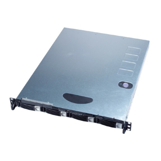
Getting Started Chapter 1. Getting Started Getting Started Congratulations on your purchase of the MS-9211 1U Rackmount Server. This high-performance barebone system ® ® supports the powerful Intel Pentium 4 processor and the industry-leading hardwares and provides the most efficient and professional solution to meet your needs. -
Page 9: Mainboard Specifications
MS-9211 1U Rackmount Server Mainboard Specifications ® Supports Intel P4 Northwood processor in 478-pin package Supports 1.5GHz~2.8GHz and up Chipset ® Intel 845E chipset - Support 100MHz/133MHz system clock ® - Intel NetBurst micro-architecture supports 400MHz/533MHz system bus ® Intel ICH4 chipset - Hi-Speed USB (USB2.0) controller, 480Mb/sec - PCI Master 2.2... - Page 10 Getting Started - Onboard 8MB video SDRAM. ® Option 1: Dual Intel 82551 10/100Mbps LAN controllers. ® ® Option 2: One Intel 82551 10/100Mbps LAN controller & One Intel 82540 1Gbps LAN controller. Server Management (optional) ® National Semiconductor PC87431HM mBMC (mini-Baseboard Manage- ment Controller) - Incorporates an embedded microcontroller, three System Management ®...
-
Page 11: Mainboard Layout
MS-9211 1U Rackmount Server Mainboard Layout CFAN1 Top : mouse PSFAN1 Bottom: keyboard JPW1 ports Intel 845E LAN 1 Chipset LAN 2 Intel LAN Chip COM 2 +BATT PCI 1 Intel LAN Chip JBAT1 ICH 4 LED1 LED2 LED3 LED4 IDE 3 LED5 LED6... -
Page 12: Special Features
Getting Started MSI Special Features PC Alert™ III The PC Alert III is a utility you can find in the CD-ROM disk. The utility is just like your PC doctor that can de- tect the following PC hardware status during real time operation: monitor CPU &... -
Page 13: D-Led™ (Optional)
MS-9211 1U Rackmount Server D-LED™ (Optional) The D-LED™ (Diagnostic LED) uses graphic signal display to help users understand their system. Four LEDs (LED1 ~ LED4) embedded on the main- board provide up to 16 combinations of signals to debug the system. The 4 LEDs can debug all problems that fail the system, such as VGA, RAM or other failures. - Page 14 Getting Started Processor Initialization - This will show information regarding the processor (like brand name, system bus, etc…) Testing RTC (Real Time Clock) Initializing Video Interface - This will start detecting CPU clock, checking type of video onboard. Then, detect and initialize the video adapter. BIOS Sign On - This will start showing information about logo, processor brand name, etc….
-
Page 15: Lcd Front Panel Control
MS-9211 1U Rackmount Server LCD Front Panel Control Installing the LCD Control Service Version: V2.2 OS supported: Windows NT 4 with Service Pack 4 or latest version Windows 2000, Windows XP Step 1: Insert the installation CD into the CD-ROM drive. Browse to the CD- ROM drive and double-click the executable file “setup.exe”... - Page 16 Getting Started Step 4: Setup has finished installing the LCD Control service on your computer. Click Install service to enable the LCD Control service. Step 5: Click OK to continue. You can restart the computer now.
- Page 17 MS-9211 1U Rackmount Server Un-installing the LCD Control Service Step 1: Click Start, and then point to Programs. Under Programs, Click LCD Control Panel and the following screen will pop up. Click Remove service to disable the LCD Control service. Step 2: Click OK to continue.
-
Page 18: Lcd Function Menu
Getting Started LCD Function Menu Here shows the LCD Front Panel and its three control buttons. Enter Next Go to the previous selection. Enter Execute the command. Next Go to the next selection. After you have installed the LCD Control Panel Service, you can simply use the LCD Front Panel Control buttons to get access to the information under LCD Info, H/W Monitor and System Conf menus. - Page 19 MS-9211 1U Rackmount Server Host name Date Set Date Time Set Time Size Memory Usage Available Size Disk C Usage Available Size Hard Disk Usage Disk D Information Available Size Disk E Usage Available System Conf Size Usage Disk F Available Net Mask LAN1...
- Page 20 Getting Started Before Boot to OS (Debug Function) Function Description LCD Panel v1.1 Show product information and version Initialize OK BIOS POST: C1 If the system has memory issues, it will stop at C1. Msg: Mem Sizing BIOS POST: C3 If the system has BIOS issues, it will stop at C3.
- Page 21 MS-9211 1U Rackmount Server LCD Info Function Description Firmware Show LCD Firmware version V1.1 Mode Show LCD working mode Communication Build date Show LCD Firmware build date 2002/03/25 Baud Rate Show LCD communication speed with COM port 9600 For PC and LCD link Character Show LCD characters 16X2...
- Page 22 Getting Started H/W Monitor Function Description 1/15 Show CPU temperature information Chassis 2/15 Show chassis temperature information System FAN 3/15 Show System FAN speed information 0 RPM Power FAN 4/15 Show Power FAN speed information 4219 RPM CPU FAN 5/15 Show CPU FAN speed information 0 RPM V core...
- Page 23 MS-9211 1U Rackmount Server System Conf Function Description Host name Show system’s host name Date Set Date 1/1 Show the date and allow to set the date 2002.8.21 Time Set Time 1.1 Show the time and allow to set the time 13:24:50 Memory Size 1/3...
- Page 24 Getting Started System Conf (continued) Function Description Available 3/3 Unable to show the available size Disk F 4/4 Size 1/3 Show this partition’s size Usage 2/3 Unable to show the used size Available 3/3 Unable to show the available size LAN1 IP 1/4 Show the system IP information...
-
Page 25: System Configuration
MS-9211 1U Rackmount Server System Configuration This section shows the configuration of the MS-9211 from different angles, and the connectors and buttons on the front and back panel. Front View after enlargement LCD Front Panel Slim CD-ROM Drive (optional) LED Indicators Power Button USB Ports LCD Control Buttons... - Page 26 Getting Started Power Button This main power button is used to turn on or off the system. Power Indicator This indicator shows the power status of the system. It glows when the main power is turned on. LAN Status Indicators These two LED indicators flash to show the activity status on LAN1 and LAN2.
-
Page 27: Rear View
MS-9211 1U Rackmount Server Rear View after enlargement Power Connector Heat Dissipation Opening PS/2 Keyboard Connector PS/2 Mouse Connector Serial Port COM A VGA Port LAN Jacks 1 & 2 USB Ports 1 & 2 1-20... -
Page 28: Top View
Getting Started Top View ATX Power Supply Slim CD-ROM Drive (optional) DIMM Slots Riser Card Bracket CPU Socket Blower AC Power Connector 1-21... -
Page 29: Packing Checklist
MS-9211 1U Rackmount Server Packing Checklist Unpack the package and check if all items listed below are present. If any item contained in the package is damaged or missing, please contact your local dealer for replacement. In addition, keep the box and packing materials for possible future use. - Page 30 Getting Started Ear Set M4x6 black screws x4 M5x12 screws x2 2 ears Chassis Rail Bracket Set 4 secure plates 4 brackets M5x8 screws x8 M4 Nut x8 M4x6 screws x8 Rail Set M4x4 screws x8 2 rails 1-23...
-
Page 31: Chapter 2. Hardware Setup
Hardware Setup Chapter 2. Hardware Setup Hardware Setup This chapter provides you with the information about hard- ware setup procedures. While doing the installation, be careful in holding the components and follow the installation procedures. For some components, if you install in the wrong orientation, the components will not work properly. -
Page 32: Central Processing Unit: Cpu
MS-9211 1U Rackmount Server Central Processing Unit: CPU ® The mainboard supports Intel P4 Northwood processor in the 478 pin package. The mainboard uses a CPU socket called PGA478 for easy CPU installation. When you are installing the CPU, make sure the CPU has a heat sink and a cooling fan attached on the top to prevent overheating. -
Page 33: Memory
Hardware Setup Memory The mainboard provides 2 slots for 184-pin DDR SDRAM DIMM (Double In-Line Memory Module) modules and supports the memory size up to 2GB. You can install PC2100/DDR266 or PC1600/DDR200 modules on the DDR DIMM slots (DIMM 1~2). DDR DIMM Slots (DIMM 1~2) Introduction to DDR SDRAM... -
Page 34: Dimm Module Combination
MS-9211 1U Rackmount Server DIMM Module Combination Install at least one DIMM module on the slots. Memory modules can be installed on the slots in any order. You can install either single- or double- sided modules to meet your own needs. Memory modules can be installed in any combination as follows: Slot Memory Module... -
Page 35: Power Supply
Hardware Setup Power Supply The mainboard supports ATX power supply for the power system. Be- fore inserting the power supply connector, always make sure that all compo- nents are installed properly to ensure that no damage will be caused. ATX 20-Pin Power Connector: JWR1 This connector allows you to connect to an ATX power supply. -
Page 36: Back Panel
MS-9211 1U Rackmount Server Back Panel The back panel provides the following connectors: Mouse Keyboard COM 1 Mouse Connector ® The mainboard provides a standard PS/2 mouse mini DIN connector ® ® for attaching a PS/2 mouse. You can plug a PS/2 mouse directly into this connector. -
Page 37: Keyboard Connector
Hardware Setup Keyboard Connector ® The mainboard provides a standard PS/2 keyboard mini DIN connec- ® ® tor for attaching a PS/2 keyboard. You can plug a PS/2 keyboard directly into this connector. Pin Definition SIGNAL DESCRIPTION Keyboard DATA Keyboard DATA No connection Ground Keyboard Clock... -
Page 38: Serial Port Connectors: Com1 & Com2
MS-9211 1U Rackmount Server Serial Port Connectors: COM 1 & COM2 The mainboard offers two 9-pin connectors as serial port COM 1 & COM 2. The ports are 16550A high speed communication ports that send/ receive 16 bytes FIFOs. You can attach a serial mouse or other serial devices directly to the connectors. -
Page 39: Rj-45 Lan Jacks: 10/100 Lan Or Giga-Bit Lan
Hardware Setup RJ-45 LAN Jacks: 10/100 LAN or Giga-bit LAN The mainboard provides two standard RJ-45 jacks for connection to Local Area Network (LAN). Two options are available upon request: 1. Dual 10/100 LAN. 2. One 10/100 LAN & one Giga-bit LAN. Giga-bit LAN enables data to be transferred at 1000, 100 or 10Mbps. -
Page 40: Connectors
MS-9211 1U Rackmount Server Connectors The mainboard provides connectors to connect to FDD, IDE HDD, case, modem, LAN, USB Ports, IR module and CPU/System/Power Supply FAN. Floppy Disk Drive Connector: FDD1 The mainboard provides a standard floppy disk drive connector that supports 360K, 720K, 1.2M, 1.44M and 2.88M floppy disk types. -
Page 41: Hard Disk Connectors: Ide1 & Ide2
Hardware Setup Hard Disk Connectors: IDE1 & IDE2 The mainboard has a 32-bit Enhanced PCI IDE and Ultra DMA 66/100 controller that provides PIO mode 0~4, Bus Master, and Ultra DMA 66/100 function. You can connect up to four hard disk drives, CD-ROM, 120MB Floppy (reserved for future BIOS) and other devices. -
Page 42: Ata133 Raid Connectors: Ide3 & Ide4 (Optional)
MS-9211 1U Rackmount Server ATA133 RAID Connectors: IDE3 & IDE4 (Optional) The mainboard offers high-end Ultra ATA/133 RAID (0 or 1) hard drive ® interface specifications supported through Promise PDC20276 controller . The Ultra ATA/133 interface boosts data transfer rates between the com- puter and the hard drive up to 133 megabytes (MB) per second. -
Page 43: Fan Power Connectors: Cfan1/Sfan1/Psfan1
Hardware Setup Fan Power Connectors: CFAN1/SFAN1/PSFAN1 The CFAN1 (processor fan), SFAN1 (system fan), and PSFAN1 (power supply fan) support system cooling fan with +12V. It supports three-pin head connector. When connecting the wire to the connectors, always take note that the red wire is the positive and should be connected to the +12V, the black wire is Ground and should be connected to GND. -
Page 44: Front Panel Connector: Jfp1
MS-9211 1U Rackmount Server Front Panel Connectors: JFP1 The mainboard provides one front panel connector for electrical con- nection to the front panel switches and LEDs. The JFP1 is compliant with ® Intel Front Panel I/O Connectivity Design Guide. Power Power Switch JFP1... -
Page 45: Front Usb Connectors: Jusb2, Jusb3
Hardware Setup Front USB Connectors: JUSB2, JUSB3 The mainboard provides two USB 2.0 pin headers JUSB2 & JUSB3 ® (optional USB 2.0 bracket available) that are compliant with Intel I/O Con- nectivity Design Guide. USB 2.0 technology increases data transfer rate up to a maximum throughput of 480Mbps, which is 40 times faster than USB 1.1, and is ideal for connecting high-speed USB interface peripherals such as USB HDD, digital cameras, MP3 players, printers, modems and the like. - Page 46 MS-9211 1U Rackmount Server To Attach the Optional USB 2.0 Ports: 1. Take out the USB2.0 Bracket (optional accessory upon request). 2. Locate the USB pinheaders JUSB2 and JUSB3 on the motherboard. 3. Connect the USB cables from USB 2.0 bracket to the JUSB2 and JUSB3 pin headers separately.
-
Page 47: Irda Infrared Module Header: Ir2
Hardware Setup IrDA Infrared Module Header: IR2 The connector allows you to connect to IrDA Infrared module. You must configure the setting through the BIOS setup to use the IR function. The ® IR2 is compliant with Intel Front Panel I/O Connectivity Design Guide. Pin Definition Signal VCC5... -
Page 48: Lan Led Connectors: Jact1, Jact2
MS-9211 1U Rackmount Server LAN LED Connectors: JACT1, JACT2 The LAN LED connectors are used to connect to LAN LEDs, which show the activity of the LAN. JACT1 is for LAN 1 jack and the JACT2 is for LAN2 jack. Both LAN1 & LAN2 jacks are located on the back panel. JACT1 JACT2 LCD Panel Connector: JLCD1... -
Page 49: Diagnostic Leds: Led1, Led2, Led3, Led4 (Optional)
Hardware Setup Diagnostic LEDs: LED1, LED2, LED3, LED4 (Optional) The mainboard comes with four LEDs and allows users to identify sys- tem problem through 16 various combinations of LED signals. For defini- tions of 16 signal combinations, please refer to D-LED™ in Chapter 1. LED1 LED2 LED3... -
Page 50: Jumpers
MS-9211 1U Rackmount Server Jumpers The motherboard provides the following jumpers for you to set the computer’s function. This section will explain how to change your motherboard’s function through the use of jumpers. Clear CMOS Jumper: JBAT1 There is a CMOS RAM on board that has a power supply from external battery to keep the data of system configuration. -
Page 51: Slots
Hardware Setup Slots The motherboard provides one 32-bit Master PCI bus slot. PCI Slot PCI (Peripheral Component Interconnect) Slot The PCI slot allows you to insert the expansion card to meet your needs. When adding or removing the expansion card, make sure that you unplug the power supply first. -
Page 52: Chapter 3. Bios Setup
BIOS Setup Chapter 3. BIOS Setup BIOS Setup This chapter provides information on the BIOS Setup pro- gram and allows you to configure the system for optimum use. You may need to run the Setup program when: An error message appears on the screen during the system booting up, and requests you to run SETUP. -
Page 53: Entering Setup
MS-9211 1U Rackmount Server Entering Setup Power on the computer and the system will start POST (Power On Self Test) process. When the message below appears on the screen, press <DEL> key to enter Setup. P r e s s D E L t o e n t e r S E T U P If the message disappears before you respond and you still wish to enter Setup, restart the system by turning it OFF and On or pressing the RESET button. -
Page 54: Getting Help
BIOS Setup Getting Help After entering the Setup menu, the first menu you will see is the Main Menu. Main Menu The main menu lists the setup functions you can make changes to. You can use the arrow keys ( to select the item. -
Page 55: The Main Menu
MS-9211 1U Rackmount Server The Main Menu Once you enter Phoenix-Award WorkstationBIOS CMOS Setup Utility, the Main Menu will appear on the screen. The Main Menu displays thirteen configurable functions and two exit choices. Use arrow keys to move among the items and press <Enter>... - Page 56 BIOS Setup Power Management Setup Use this menu to specify your settings for power management. PNP/PCI Configurations This entry appears if your system supports PnP/PCI. PC Health Status (for mainboards without mBMC chip) This entry shows your PC health status. Frequency/Voltage Control Use this menu to specify your settings for frequency/voltage control.
-
Page 57: Standard Cmos Features
MS-9211 1U Rackmount Server Standard CMOS Features The items inside Standard CMOS Features menu are divided into 10 categories. Each category includes none, one or more setup items. Use the arrow keys to highlight the item you want to modify and use the <PgUp> or <PgDn>... - Page 58 BIOS Setup your hard disk drive type is not matched or listed, you can use Manual to define your own drive type manually. If you select Manual, related information is asked to be entered to the follow- ing items. Enter the information directly from the keyboard. This information should be provided in the documentation from your hard disk vendor or the system manufacturer.
-
Page 59: Ipmi V1.5 Bios Features
MS-9211 1U Rackmount Server IPMI V1.5 BIOS Features This setup screen appears only when the mBMC chip (for Server Management) is integrated on the mainboard. PEF Configuration Status This option shows the current Platform Event Filter (PEF) configuration status. (Read only) Setting PEF Configuration This setting is used to set the Platform Event Filter (PEF) configuration. - Page 60 BIOS Setup able on expiration of the Watchdog Timer: No Action, Hard Reset, Power Down, Power Cycle. WatchDog Timer Counter This feature allows users to set the time interval to reboot the computer if a timeout event occurs. Setting options: 10 Sec, 20 Sec, 30 Sec, 40 Sec.
-
Page 61: Advanced Bios Features
MS-9211 1U Rackmount Server Advanced BIOS Features Hard Disk Boot Priority This setting determines the boot priority of the installed hard disks. Virus Warning The item is to set the Virus Warning feature for IDE Hard Disk boot sector protection. If the function is enabled and any attempt to write data into this area is made, BIOS will display a warning message on screen and beep. - Page 62 BIOS Setup CPU L1 & L2 Cache Cache memory is additional memory that is much faster than conventional DRAM (system memory). When the CPU requests data, the system transfers the requested data from the main DRAM into cache memory, for even faster access by the CPU.
- Page 63 MS-9211 1U Rackmount Server MSI Reminds You... Available settings for “First/Second/Third Boot Device” vary depending on the bootable devices you have installed. For example, if you did not install a floppy drive, the setting “Floppy” does not show up. Boot Other Device Setting the option to Enabled allows the system to try to boot from other devices if the system fails to boot from the 1st/2nd/3rd boot device.
- Page 64 BIOS Setup (characters/second) at which the keys are accelerated. Settings: 6, 8, 10, 12, 15, 20, 24 and 30. Typematic Delay (Msec) This item allows you to select the delay between when the key was first pressed and when the acceleration begins. Settings: 250, 500, 750 and 1000. Security Option This specifies the type of BIOS password protection that is implemented.
- Page 65 MS-9211 1U Rackmount Server terminal screen. Besides, all data received from the serial port is interpreted as keystrokes from a local keyboard. Setting options: Enabled, Disabled. Baud Rate This setting specifies the transfer rate (bits per second) of Console Redirection. Setting options: 9600, 19200, 38400, 57600, 115200.
-
Page 66: Advanced Chipset Features
BIOS Setup Advanced Chipset Features MSI Reminds You... Change these settings only if you are familiar with the chipset. DRAM Timing Selectable This setting determines whether DRAM timing is configured by reading the contents of the SPD (Serial Presence Detect) EPROM on the DRAM module. Selecting By SPD makes the following settings automatically determined by BIOS according to the configurations on the SPD. - Page 67 MS-9211 1U Rackmount Server separately. This setup item allows you to determine the timing of the transition from RAS (row address strobe) to CAS (column address strobe). The less the clock cycles, the faster the DRAM performance. Setting options: 3, 2. DRAM RAS# Precharge This item controls the number of cycles for Row Address Strobe (RAS) to be allowed to precharge.
- Page 68 BIOS Setup 16MB. When this area is reserved, it cannot be cached. Setting options: Disabled, Enabled. Delayed Transaction The chipset has an embedded 32-bit posted write buffer to support delayed transactions cycles so that transactions to and from the ISA bus are buffered and PCI bus can perform other transactions while the ISA transaction is underway.
-
Page 69: Integrated Peripherals
MS-9211 1U Rackmount Server Integrated Peripherals On-Chip Primary/Secondary PCI IDE The integrated peripheral controller contains an IDE interface with support for two IDE channels. Choose Enabled to activate each channel separately. IDE Primary/Secondary Master/Slave PIO The four items allow you to set a PIO (Programmed Input/Output) mode for each of the four IDE devices that the onboard IDE interface supports. - Page 70 BIOS Setup USB 2.0 Support This setting disables/enables the support for USB 2.0 technology. USB 2.0 technology increases data transfer rate up to a maximum throughput of 480Mbps, which is 40 times faster than USB 1.1 and is ideal for connecting high-speed USB interface peripherals such as USB HDD, digital cameras, MP3 players, printers, modems and the like.
- Page 71 MS-9211 1U Rackmount Server Normal RS-232C Serial Port IrDA IrDA-compliant Serial Infrared Port ASKIR Amplitude Shift Keyed Infrared Port RxD, TxD Active This setting controls the receiving and transmitting speed of the IR peripheral in use. Setting options: Hi/Hi, Hi/Lo, Lo/Hi, Lo/Lo. IR Transmission Delay This setting determines whether the IR transmission rate will be delayed while converting to receiving mode.
-
Page 72: Power Management Setup
BIOS Setup Power Management Setup MSI Reminds You... S3-related functions described in this section are available only when your BIOS supports S3 sleep mode. ACPI Function This item is to activate the ACPI (Advanced Configuration and Power Man- agement Interface) function. If your operating system is ACPI-aware, such as Windows 98SE/2000/ME, select Enabled. - Page 73 MS-9211 1U Rackmount Server Video Off Method This determines the manner in which the monitor is blanked. V/H SYNC+Blank This selection will cause the system to turn off the vertical and horizontal synchronization ports and write blanks to the video buffer. Blank Screen This option only writes blanks to the video buffer.
- Page 74 BIOS Setup Settings range from 12.5% to 87.5% at 12.5% increment. Wake-Up by PME When setting to Enabled, the feature allows your system to be awakened from the power saving modes through any event on PME (Power Management Event). Settings: Enabled and Disabled. Resume By Alarm The field is used to enable or disable the feature of booting up the system on a scheduled time/date.
-
Page 75: Pnp/Pci Configurations
MS-9211 1U Rackmount Server PNP/PCI Configurations This section describes configuring the PCI bus system and PnP (Plug & Play) feature. PCI, or Peripheral Component Interconnect, is a system which allows I/O devices to operate at speeds nearing the speed the CPU itself uses when communicating with its special components. - Page 76 BIOS Setup IRQ Resources The items are adjustable only when Resources Controlled By is set to Manual. Press <Enter> and you will enter the sub-menu of the items. IRQ Resources list IRQ 3/4/5/7/9/10/11/12/14/15 for users to set each IRQ a type depending on the type of device using the IRQ.
-
Page 77: Pc Health Status
MS-9211 1U Rackmount Server PC Health Status This setup screen monitors the status of your CPU, fan, overall system status,.. etc and will not show up when the mBMC chip (for Server Management) is integrated on the mainboard. Monitor function is available only if there is hardware monitoring mechanism onboard. -
Page 78: Frequency/Voltage Control
BIOS Setup Frequency/Voltage Control Use this menu to specify your settings for frequency/voltage control. CPU Clock Ratio This setting controls the multiplier that is used to determine the internal clock speed of the processor relative to the external or motherboard clock speed. Auto Detect PCI Clk This item is used to auto detect the PCI slots. -
Page 79: Load Fail-Safe/Optimized Defaults
MS-9211 1U Rackmount Server Load Fail-Safe/Optimized Defaults The two options on the main menu allow users to restore all of the BIOS settings to the default Fail-Safe or Optimized values. The Optimized Defaults are the default values set by the mainboard manufacturer specifically for op- timal performance of the mainboard. -
Page 80: Set Supervisor/User Password
BIOS Setup Set Supervisor/User Password When you select this function, a message as below will appear on the screen: Type the password, up to six characters in length, and press <Enter>. The password typed now will replace any previously set password from CMOS memory. -
Page 81: Chapter 4. Chassis Installation
Chassis Installation Chapter 3. BIOS Setup Chassis Installation This chapter provides instructions on the hardware instal- lation of the MS-9211 in two sections. System Assembly illus- trates how to assembly each component of the MS-9211. Rack Mounting describes the procedures for mounting the unit into the rack in details. -
Page 82: System Assembly Flowchart
MS-9211 1U Rackmount Server System Assembly Flowchart The following flowchart shows basic system assembly procedures. Please note that always wear anti-static gloves when handling electrical components and exercise caution during the installation process. For more information, contact your local dealer or experienced technician. START REMOVE CHASSIS COVER AND FAN DUCT... - Page 83 Chassis Installation CONNECT HDD, FDD, CD-ROM CABLES & POWER CORDS REMOVE RISER CARD BRACKET INSTALL RISER CARD REPLACE RISER CARD BRACKET CHECK IF ALL PARTS ARE PROPERLY CONNECTED REPLACE CHASSIS COVER FINISH...
-
Page 84: System Assembly
MS-9211 1U Rackmount Server System Assembly Chassis Cover Locate the release buttons on the chassis cover. Press the release buttons and then push the cover backward to lift it up. To replace the cover, slide the cover forward and make sure the safety lock fits firmly. -
Page 85: Cpu, Heatsink And Fan Duct
Chassis Installation CPU, Heatsink and Fan Duct Remove the fan duct. Locate the CPU socket and lift the lever up to a 90 degree angle. CPU lever up Place the CPU on top of the socket with the gold arrow pointing to the lever. - Page 86 MS-9211 1U Rackmount Server CPU, Heatsink and Fan Duct (continued) Locate the four points of the heatsink socket. Locate the four screw holes of the PHP122 heatsink. Position the PHP122 heatsink onto the heatsink socket carefully to avoid damaging the components around. Screw the heatsink to the chassis following a diagonal sequence.
- Page 87 Chassis Installation Plug in the power cord of the PHP122 heatsink. Replace the fan duct to ensure proper heat dissipation. You have finished installing the heatsink and fan duct.
-
Page 88: Dimm
MS-9211 1U Rackmount Server DIMM Locate the DIMM slots on the mainboard. Insert the SDRAM module into the DIMM slot. The plastic clip at each side of the DIMM slot will automati- cally close. -
Page 89: Hard Disk Drives
Chassis Installation Hard Disk Drives Unscrew the HDD cover plate. Turn over the HDD cover plate. Remove the right bracket. Place the first hard disk drive into the chassis and make sure the cables are properly connected. - Page 90 MS-9211 1U Rackmount Server Hard Disk Drives (continued) Replace the right bracket. Follow the same procedures to install the second hard disk drive. Replace the HDD cover plate. Screw the HDD cover plate in place. 4-10...
-
Page 91: Riser Card
Chassis Installation Riser Card Remove the riser card bracket. Unscrew the I/O shield from the riser card bracket. Save the screw for later use. Insert the SCSI card into the bracket. Screw the SCSI card firmly to the riser card bracket. 4-11... - Page 92 MS-9211 1U Rackmount Server Replace the riser card bracket. 4-12...
-
Page 93: Rack Mounting
Chassis Installation Rack Mounting Chassis Rails and Ears Screw the ears to both sides of the chassis. M4x6 black Screw the side rails to both sides of the chassis. M4x6 TIPS Attach the brackets (front and rear) onto the rails; the position of the rear bracket should be adjustable, which depends on the place where the system is installed into the rack. -
Page 94: Chassis Into The Rack
MS-9211 1U Rackmount Server Chassis into the Rack Screw the rails onto the rack. M5x8 Align the chassis rails with the rack rails, and then push the system into the rack fully Note: The chassis rails must match the rack rails well, and the ball bearing set of the rack rails should clip into the fillister on the chassis rails. -
Page 95: Locking Tab
Chassis Installation Locking Tab To slide the system into the rack, first align the chassis rails with the rack rails. Then simultaneously press the locking tabs on both sides of the chassis rails and slide the system backward. The system will be locked halfway while pulling it out.
Need help?
Do you have a question about the MS - 9211 and is the answer not in the manual?
Questions and answers