Table of Contents
Advertisement
Quick Links
Advertisement
Table of Contents

Related Manuals for MSI MS-9218


Summary of Contents for MSI MS-9218
- Page 1 MS-9218 1U Rackmount Server English Version G52-S9218X1...
-
Page 2: Copyright Notice
If a problem arises with your system and no solution can be obtained from the user’s manual, please contact your place of purchase or local distributor. Alternatively, please try the following help resources for further guidance. Visit the MSI website for FAQ, technical guide, BIOS updates, driver updates, and other information: http://www.msi.com.tw/program/service/faq/ faq/esc_faq_list.php... -
Page 3: Safety Instructions
Safety Instructions Always read the safety instructions carefully. Keep this User’s Manual for future reference. Keep this equipment away from humidity. Lay this equipment on a reliable flat surface before setting it up. The openings on the enclosure are for air convection hence protects the equip- ment from overheating. -
Page 4: Fcc-A Radio Frequency Interference Statement
VOIR LA NOTICE D’INSTALLATION AVANT DE RACCORDER AU RESEAU. Micro-Star International MS-9218 This device complies with Part 15 of the FCC Rules. Operation is subject to the following two conditions: (1) this device may not cause harmful interference, and (2) this device must accept any interference received, including interference that may cause undesired operation. -
Page 5: Weee (Waste Electrical And Electronic Equipment) Statement
WEEE (Waste Electrical and Electronic Equipment) Statement... -
Page 8: Table Of Contents
Un-installing the LCD Control Service ................ 1-9 LCD Function Menu ....................1-10 System Specifications ..................1-16 Mainboard Layout ....................1-18 MSI Special Features ..................1-19 PC Alert™ III ....................1-19 Chapter 2. System Hardware ................2-1 System Assembly Flowchart ................2-2 System Assembly .................... - Page 9 Central Processing Unit: CPU ................3-3 Introduction to LGA 775 CPU ..............3-3 CPU, Heatsink, and Heat Pipe Cooler ............3-4 Memory ......................... 3-6 Introduction to DDR2 SDRAM ..............3-6 Memory Module Population Rules ............... 3-6 Installing DDR2 Modules ................3-7 Power Supply ......................
- Page 10 Chapter 4. BIOS Setup .................... 4-1 Entering Setup ..................... 4-2 Getting Help ....................4-2 General Help <F1> ..................4-2 The Menu Bar ...................... 4-3 Main ........................4-4 Advanc ed ......................4-7 Security ......................4-16 Power ......................... 4-17 Boot ........................4-18 Exit ........................
-
Page 11: Chapter 1. Getting Started
® system powered by Intel Pentium 4 / Pentium D processors, ® ® Intel E7230, and Intel ICH7R chipsets. W ith high scalability, reliability, ease of use, and overall value, the MS-9218 makes an ideal choice for value conscious customers. -
Page 12: System Overview
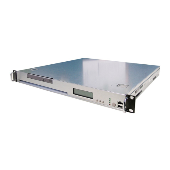
MS-9218 1U Rackmount Server System Overview This section shows the configuration of the MS-9218 from different angles, and the connectors and buttons on the front and back panel. Top View Slim CD-ROM Drive HDD Tray EPS 1U Power Supply Heat Pipe Cooler... -
Page 13: Front View
Getting Started Front View LCD Front Panel Slim CD-ROM Drive LED Indicators Power Button USB Ports LCD Control Buttons... - Page 14 MS-9218 1U Rackmount Server Power Button This main power button is used to turn on or off the system. Power Indicator This indicator shows the power status of the system. It glows when the main power is turned on. LAN Status Indicators These two LED indicators flash to show the activity status on LAN1 and LAN2.
-
Page 15: Rear View
Getting Started Rear View AC Power Connector PCI Express Card Bracket PS/2 Mouse/Keyboard Parallel Port Serial Port VGA Port USB Ports Gigabit LAN Jacks s Rear I/O LEDs Color State Description RJ45 NIC 1 Linkage Green LAN linked /RJ45 NIC 2 Linkage Green Blinking LAN accessing... - Page 16 MS-9218 1U Rackmount Server M ouse/Keyboard Connector USB Port SIGNAL -Data +Data SIGNAL DESCRIPTION Mouse/Keyboard Data Mouse/Keyboard data Serial Port No connection Ground 1 2 3 4 5 Mouse/Keyboard Clock Mouse/Keyboard clock No connection 6 7 8 9 SIGNAL VGA Port...
-
Page 17: Lcd Front Panel Control
Getting Started LCD Front Panel Control Installing the LCD Control Service Version: V3.0 OS supported: W indows NT 4 with Service Pack 4 or latest version W indows 2000, W indows 2003, W indows XP Step 1: Insert the application CD into the CD-ROM drive. Browse to the CD-ROM drive and double-click the executable file “setup.exe”... - Page 18 MS-9218 1U Rackmount Server Step 4: Setup has finished installing the LCD Control service on your computer. Click Install service to enable the LCD Control service.
-
Page 19: Un-Installing The Lcd Control Service
Getting Started Un-installing the LCD Control Service Step 1: Click Start, and then point to Programs. Under Programs/ MSI / LCD Control Service, Click LCD Control Panel and the following scree will pop up. Click Remove service to disable the LCD Control service. -
Page 20: Lcd Function Menu
MS-9218 1U Rackmount Server LCD Function Menu Here shows the LCD Front Panel and its three control buttons. Enter Next Go to the previous selection Enter Execute the command Next Go to the next selection After you have installed the LCD Control Panel Service, you can simply use the LCD Front Panel Control buttons to get access to the information under LCD Info, H/W Monitor and System Conf menus. -
Page 21: Getting Started
Getting Started Seq 1 Seq 2 S.R. GUID Seq 3 Seq 4 Host name Seq 5 Set Date Da te Asset Tag T ime Set Time Size Memory Usage Available Size Disk C Usage Available Size Hard Disk Usage Disk D Informa tion Available Size... - Page 22 MS-9218 1U Rackmount Server Before Boot to OS (Debug Function) Function Description LCD Panel v1.1 Show product information and version Initialize OK BIOS POST: C1 If the system has memory issues, it will stop at C1. Msg: Mem Sizing BIOS POST: C3 If the system has BIOS issues, it will stop at C3.
- Page 23 Getting Started LCD Info Function Description Firmware Show LCD Firmware version V1.1 Mode Show LCD working mode Communication Build date Show LCD Firmware build date 2002/03/25 Baud Rate Show LCD communication speed with COM port 9600 For PC and LCD link Character Show LCD characters 16X2...
- Page 24 MS-9218 1U Rackmount Server System Conf Function Description S.R. GUID 1/11 Universal Unique ID number Host name 2/11 Show system’s host name Date 3/11 Set Date 1/1 Show the date and allow to set the date 2005.8.26 Asset Tag 4/11...
- Page 25 Getting Started System Conf (continued) Function Description LAN1 8/11 IP 1/6 Show the system IP information 100.100.100.101 100.100.100.101 Netmask 2/6 Show the system Net Mask information 255.255.255.0 Gateway 3/6 Show the system gateway information Set IP 4/6 Allow users to set the system’s IP 000.000.000.000 Set Gateway 5/6 Allow users to set system’s gateway Setmask 6/6...
-
Page 26: System Specifications
Slots † One PCI Express x8 slot (this PCIE_1 slot will accept x8 cards and run at x8 speeds / with an extra PCIE_3 slot for MSI proprietary riser cards / PCI Express Bus specification v1.0a compliant) HDD Interface †... - Page 27 Getting Started Onboard Peripherals † 1 floppy port supports one FDD with 360KB, 720KB, 1.2MB, 1.44MB, and 2.88MB † 1 PS/2 keyboard port † 1 PS/2 mouse port † 1 serial port & 1 serial pinheader † 1 VGA port †...
-
Page 28: Mainboard Layout
MS-9218 1U Rackmount Server Mainboard Layout Top: Mou se B otto m: K ey boar d CPU _FA N1 Top: P ara llel P ort B otto m: C OM A V GA Po rt JACT1 U SB JACT2 P ort s... -
Page 29: Msi Special Features
Getting Started MSI Special Features PC Alert™ III The PC Alert III is a utility you can find in the application CD. The utility is just like your PC doctor that can detect the following PC hard- ware status during real time operation: ö... -
Page 30: Chapter 2. System Hardware
System Hardware This chapter provides instructions on the hardware installation of the MS-9218 in two sections. System Assembly illustrates how to as- semble each component of the MS-9218. Rack Mounting describes the procedures for mounting the unit into the rack in details. You can... -
Page 31: System Assembly Flowchart
MS-9218 1U Rackmount Server System Assembly Flowchart The following flowchart shows basic system assembly procedures. Please note that always wear anti-static gloves when handling electrical components and exercise caution during the installation process. For more information, contact your local dealer or experienced technician. - Page 32 System Hardware INSTALL RISER CARDS REPLACE RISER CARD BRACKET INSTALL HARD DISK DRIVES CONNECT HDD & POWER CORDS CHECK IF ALL PARTS ARE PROPERLY CONNECTED REPLACE CHASSIS COVER FINISH...
-
Page 33: System Assembly
MS-9218 1U Rackmount Server System Assembly Removing the Chassis Cover 1. Locate the release buttons on the chassis cover. Press the release buttons and then push the cover backwards. 2. Lift the cover up from the chassis. -
Page 34: Replacing The Chassis Cover
1. Replace the chassis cover. 2. Slide the cover forwards and make sure the safety lock fits firmly. MSI Reminds You... Before you remove or install any components, make sure the server is not turned on or connected to the AC power. -
Page 35: Cpu, Heatsink, And Heat Pipe Cooler
MS-9218 1U Rackmount Server CPU, Heatsink, and Heat Pipe Cooler 1. Locate the CPU socket. 2. Raise the load lever up to its full extent. 3. Open the load plate. 4. After confirming the CPU direction (indicated below with red circles) for correct mating, put down the CPU in the socket housing frame. -
Page 36: System Hardware
9. Screw the heatsink to the chassis. 10. Connect the fan power cord to the onboard fan connector. MSI Reminds You... The heatsink has to be installed to prevent the CPU from overheating. 11. Replace the heat pipe cooler and screw it firmly to the chassis. -
Page 37: Ddr-Ii Memory
MS-9218 1U Rackmount Server DDR-II Memory 1. Locate the DIMM slots on the mainboard. Insert the DIMM memory module verti- cally into the DIMM slot. Then push it in until the golden finger on the memory module is deeply inserted in the socket. The plastic clip at each side of the DIMM slot will automatically close. -
Page 38: Pci Expansion Card
System Hardware PCI Expansion Card 1. Locate the riser card bracket on the chassis. 2. Lift the bracket up from the chassis. 3. Unscrew the cover plates and put them aside for later use. - Page 39 MS-9218 1U Rackmount Server 4. Insert the expansion card into the PCI Express slot on the riser card. 5. Screw the expansion card firmly to the riser card bracket. 6. Replace the riser card bracket back to the chassis. Align the riser card golden fingers with the onboard PCI Express slot.
-
Page 40: Hard Disk Drives
System Hardware Hard Disk Drives 1. Unscrew the HDD cover plate. 2. Push it forwards. 3. Lift up the HDD cover plate and turn it over. 4. Release the HDD bracket and remove it from the chassis. 2-11... - Page 41 MS-9218 1U Rackmount Server 5. Place the first HDD into the chassis and make sure the HDD fits with the chassis. 6. Connect the HDD power cord and the ATA100 cable. 7. Replace the HDD bracket. 8. Push the HDD bracket forwards to secure the HDD.
- Page 42 System Hardware 9. Follow the same procedures to install the second HDD. 10. Replace the HDD cover plate. 2-13...
- Page 43 MS-9218 1U Rackmount Server 11. Push the HDD cover plate bac kwards. 12. Note that the locking mechanism should be in the “LOCK” position. 13. Screw the HDD set securely back to the chassis. 2-14...
-
Page 44: Rack Mounting
System Hardware Rack Mounting Chassis Ears Screw the chassis ears to both sides of the chassis (as marked below). 2-15... -
Page 45: Chassis Rails
MS-9218 1U Rackmount Server Chassis Rails 1. Attach the brackets (front and rear) onto the rails; the position of the rear bracket should be adjustable, which depends on the place where the system is installed into the rack. M4 Nut... -
Page 46: Chassis Into The Rack
System Hardware Chassis into the Rack 1. Screw the rails onto the rack. M5x8 2. To slide the system into the rack, first align the chassis rails with the rack rails and push the system backwards until the locking tab clicks. 3. -
Page 47: Chassis Off The Rack
MS-9218 1U Rackmount Server Chassis off the Rack 1. To slide the system off the rack, first seize the sys tem by its ears and gently pull the system out. 2. The system will be locked halfway while being pulled out. Simulta-... -
Page 48: Chapter 3. Mainboard Hardware
Mainboard Hardware Chapter 3. Mainboard Hardware Mainboard Hardware This chapter provides you with the information about hardware setup procedures. W hile doing the installation, be careful in holding the c omponents and follow the installation procedures . For s ome components, if you install in the wrong orientation, the components will not work properly. -
Page 49: Quick Components Guide
MS-9218 1U Rackmount Server Quick Components Guide SFAN2/1, JPW1, p.3-8 p.3-16 DIMM1/2/3/4, p.3-6 CPU_FAN1, p.3-16 COM2, p.3-17 CPU, p.3-3 I/O Ports, JLCD1, p.3-17 p.3-9 ATX1, p.3-8 JUSB2, p.3-18 JACT1/2, p.3-16 JFP1, p.3-15 SATA4/ SATA3, p.3-14 IDE1, p.3-13 SFAN4, p.3-16 J5/J8, p.3-20 SFAN3, p.3-16... -
Page 50: Central Processing Unit: Cpu
If you do not have the heat sink and cooling fan, contact your dealer to purchase and install them before turning on the computer. For more information on compatible components, please visit http://www.msi.com. tw/program/products/server/svr/pro_svr_qvl.php . MSI Reminds You... -
Page 51: Cpu, Heatsink, And Heat Pipe Cooler
MS-9218 1U Rackmount Server CPU, Heatsink, and Heat Pipe Cooler 1. Locate the CPU socket. 2. Raise the load lever up to its full extent. 3. Open the load plate. 4. After confirming the CPU direction (indicated below with red circles) for correct mating, put down the CPU in the socket housing frame. - Page 52 9. Screw the heatsink to the chassis. 10. Connect the fan power cord to the onboard fan connector. MSI Reminds You... The heatsink has to be installed to prevent the CPU from overheating. 11. Replace the heat pipe cooler and screw it firmly to the chassis.
-
Page 53: Memory
DDR2 memory module in the DDR2 slot (DIMM1~DIMM4). Otherwise, you will not be able to boot up your system and your mainboard might be damaged. For more information on compatible components, please visit http://www.msi.com. tw/program/products/server/svr/pro_svr_qvl.php . DIMM1~DIMM4... -
Page 54: Installing Ddr2 Modules
256MB~1GB 256MB~1GB 256MB~1GB 1GB~4GB MSI Reminds You... - Dual-channel DDR2 works ONLY in the 5 combinations listed in the table shown in the previous page. - Please select the identical memory modules to install on the dual channel, and DO NOT install three memory modules on three DIMMs, or it may cause some failure. -
Page 55: Power Supply
MS-9218 1U Rackmount Server Power Supply The mainboard supports ATX power supply for the power system. Before inserting the power supply connector, always make sure that all components are installed properly to ensure that no damage will be caused. ATX 20-Pin System Power Connector: ATX1 This connector allows you to connect to an ATX power supply. -
Page 56: Back Panel
Mainboard Hardware Back Panel Parallel LAN1 M ou se LAN2 Keyboard COM Port VGA Port USB Ports Mouse Connector (Green) / Keyboard Connector (Purple) ® The mainboard provides a standard PS/2 mouse/keyboard mini DIN connector for ® ® attaching a PS/2 mouse/keyboard. -
Page 57: Serial Port
MS-9218 1U Rackmount Server Serial Port The mainboard offers one 9-pin male DIN connector as the serial port. The port is a 16550A high speed communication port that sends/receives 16 bytes FIFOs. You can attach a serial mouse or other serial devices directly to the connector. -
Page 58: Usb Ports
Mainboard Hardware USB Ports The rear panel provides two UHCI (Universal Host Controller Interface) Universal Serial Bus roots for attaching USB devices such as keyboard, mouse or other USB- compatible devices. You can plug the USB device directly into the connector. USB Port USB Port Description SIGNAL... -
Page 59: Parallel Port Connector: Lpt1
MS-9218 1U Rackmount Server Parallel Port Connector: LPT1 The mainboard provides a 25-pin female centronic connector as LPT. A parallel port is a standard printer port that supports Enhanced Parallel Port (EPP) and Extended Capabilities Parallel Port (ECP) mode. Pin Definition... -
Page 60: Connectors
IDE1 can connect a Master and a Slave drive. You must configure the second hard drive to Slave mode by setting the jumper accordingly. MSI Reminds You... If you install two hard disks on cable, you must configure the second drive to Slave mode by setting its jumper. -
Page 61: Serial Ata Connectors: Sata1~Sata4
MS-9218 1U Rackmount Server Serial ATA Connectors: SATA1~SATA4 The ICH7R south bridge supports four serial ATA connectors SATA1~SATA4. SATA1~SATA4 are high-speed Serial ATA interface ports. Each supports serial ATA data rates of 300MB/s and is fully compliant with Serial ATA 2.0 specifications. Each Serial ATA connector can connect to 1 hard disk device. -
Page 62: Chassis Intrusion Switch Connector: Jci1
Mainboard Hardware Chassis Intrusion Switch Connector: JCI1 This connector is connected to a 2-pin chassis switch. If the chassis is opened, the switch will be short. The system will record this status and show a warning mes- sage on the screen. To clear the warning, you must enter the BIOS utility and clear the record. -
Page 63: Power Saving Switch Connector: Jgs1
MS-9218 1U Rackmount Server Power Saving Switch Connector: JGS1 Attach a power saving switch to this connector. Press the switch once to have the system entered the Sleep/Suspend state. Press any key to wake up the system. JGS1 LAN LED Connectors: JACT1, JACT2 The LAN LED connectors are used to connect to LAN LEDs, which show the activity of the LAN. -
Page 64: Lcd Panel Connector: Jlcd1
Mainboard Hardware LCD Panel Connector: JLCD1 The connector is additionally provided for connection to a LCD panel, which shows information on the panel for you to identify the current status or mode of the con- nected system. SIGNAL JLCD1 GND1 GND0 Serial Port Header: COM2 The mainboard offers one 9-pin header as serial port. -
Page 65: Front Usb Connectors: Jusb1, Jusb2
MS-9218 1U Rackmount Server Front USB Connectors: JUSB1, JUSB2 The mainboard provides two standard USB 2.0 pinheaders. USB 2.0 technology increases data transfer rate up to a maximum throughput of 480Mbps, which is 40 times faster than USB 1.1, and is ideal for connecting high-speed USB interface peripherals such as USB HDD, digital cameras, MP3 players, printers, modems and the like. -
Page 66: Jumpers
JBAT1 Keep Data Clear Data MSI Reminds You... You can clear CMOS by shorting 2-3 pin while the system is off. Then return to 1-2 pin position. Avoid clearing the CMOS while the system is on; it will damage the mainboard. -
Page 67: Bios Write Protect Jumper: J2
MS-9218 1U Rackmount Server BIOS Write Protect Jumper: J2 A "boot block" program is included as part of the system BIOS to recover the system from a situation when the BIOS code is incorrect/corrupted or needs to be updated. W hen the BIOS code is corrupted or needs to be updated, you have to at first disable the write protect function by shorting 1-2 pin of the J2 jumper. -
Page 68: Slot
The mainboard provides: † One PCI Express x8 slot (this PCIE_1 slot will accept x8 cards and run at x8 speeds / with an extra PCIE_3 slot for MSI proprietary riser cards / PCI Express Bus specification v1.0a compliant) PCI (Peripheral Component Interconnect) Express Slots The PCI Express slots support high-bandwidth, low pin count, and serial interconnect technology. -
Page 69: Chapter 4. Bios Setup
SETUP. ² You want to change the default settings for customized features. MSI Reminds You... 1. The items under each BIOS category described in this chapter are under continuous update for better system performance. -
Page 70: Entering Setup
MS-9218 1U Rackmount Server Entering Setup Power on the computer and the system will start POST (Power On Self Test) process. W hen the message below appears on the screen, press <F1> key to enter Setup. Press F2 to enter SETUP If the message disappears before you respond and you still wish to enter Setup, restart the system by turning it OFF and On or pressing the RESET button. -
Page 71: The Menu Bar
BIOS Setup The Menu Bar Once you enter PhoenixBIOS Setup utility, the Main Menu will appear on the screen. On the Main Menu screen, you will see basic BIOS settings including system time & date, and the setup categories the BIOS supplies. Use Arrow keys to move among the items and menus, and make changes to the settings. -
Page 72: Main
MS-9218 1U Rackmount Server Main The items inside the Main menu are for basic system information and configuration. Each item includes none, one or more setup items. Use the Up/Down arrow keys or <Tab> to highlight the item or field you want to modify and use the <+> or <-> key to switch to the value you prefer. - Page 73 BIOS Setup the number of sectors transferred per block [LBA Mode Control] Enabling LBA causes Logical Block Ad- dressing to be used in place of Cylinders, Heads and Sectors. [32-Bit I/O] Enables 32-bit communication between CPU and IDE card [Tranfer Mode] Selects the method for transferring the data between the hard disk and system memory [Ultra DMA Mode]...
- Page 74 MS-9218 1U Rackmount Server QuickBoot M ode Setting the item to [Enabled] allows the system to boot within 5 seconds since it will skip some check items. Available options: [Enabled], [Disabled]. Installed M emory/ Available to OS/ Used by Devices...
-
Page 75: Advanced
BIOS Setup Advanced Items in the menu are divided into several sub-menus. Each sub-menu provides more settings. To enter the sub-menu, highligh the sub-menu you want to configure and press <Enter>. Advanced Chipset Control The sub-menu is used to configure chipset features for optimal system performance. - Page 76 MS-9218 1U Rackmount Server ECC Condition This setting specifies whether ECC Error Condition will be detected. ECC Error Handler W hen an ECC error occurs, an interrupt is generated. This setting selects the type of interrupt to report: [NMI] Non-Maskable Interrupt...
- Page 77 BIOS Setup Native Mode: * In this mode, system BIOS will search all available IRQs to use for HDD. * New OS’s that support switch to Native Mode (WinXP, Win- dows .NET Server) can set SATA and PATA to Native Mode. * Maximum 6 ATA devices to connect (4 for P-ATA &...
- Page 78 MS-9218 1U Rackmount Server MSI Reminds You... Enabling the functionality of Hyper-Threading Technology for your computer system requires ALL of the following platform components: ® ® * CPU: An Intel Pentium 4 Processor with HT Technology; ® * Chipset: An Intel Chipset that supports HT Technology;...
- Page 79 BIOS Setup Auto Fan Speed Control This item enables/disables the Smart Fan feature. Smart Fan is an excellent feature which will adjust the CPU fan speed automatically depending on the CPU current temperature, avoiding system damage caused by overheating. V(VCC5), V(Vcore), V(VCC3), V(V_1P5), V(12V), V(3Vsb), CPU/ SYS Temperature, SYS Fan1/ SYS Fan2 Speed These items display the current status of all of the monitored hardware de- vices/components such as CPU voltage, temperatures and all fans’...
- Page 80 MS-9218 1U Rackmount Server Console Redirection Press PgUp/<+> or PgDn/<-> to configure Console Redirection. The following submenu will appear. Com Port Address This feature allows you to enable/disable the Com port on the motherboard. Options: [Disabled], [On-board COM A], [On-board COM B].
- Page 81 BIOS Setup I/O Device Configuration The sub-menu is used to configure I/O Devices for optimal system performance. Integrated Device Control Sub-Menu The sub-menu is used to configure the specified integrated device. Legacy USB Support Set to [Enabled] if your need to use any USB 1.1/2.0 device in the operating system that does not support or have any USB 1.1/2.0 driver installed, such as DOS and SCO Unix.
- Page 82 MS-9218 1U Rackmount Server Serial Port A/B These settings specify the base I/O port addresses of the onboard Serial Port A / B. Selecting [Auto] allows BIOS to automatically determine the correct base I/ O port address. Settings: [3F8/IRQ4], [2F8/IRQ3], [3E8/IRQ4], [2E8/IRQ3] and [Disabled].
- Page 83 BIOS Setup DM I Event Logging Press PgUp/<+> or PgDn/<-> to view DMI event logging. View DM I Event Log Press [Enter] to view the contents of the DMI event log. Event Logging This setting disables/enables the BIOS to log DMI (Desktop Management Interface) events.
-
Page 84: Security
MS-9218 1U Rackmount Server Security This section lets you set security passwords to control access to the system at boot time and/or when entering the BIOS setup program. Supervisor Password Is/ User Password Is It shows the preset supervisor/user password. (read only) Set Supervisor Password Supervisor Password controls access to the BIOS Setup utility. -
Page 85: Power
BIOS Setup Power Use this menu to specify your settings for Power Management. Remember that the options available depend upon the hardware installed in your system. Resume On M odem Ring Select [On] to wake up the system when an incoming call is detected on the modem. Options: [On], [Off]. -
Page 86: Boot
MS-9218 1U Rackmount Server Boot Use this menu to arrange and specify the priority of the devices from which the BIOS will attempt to boot the Operating System. Boot Priority Order This setting allows users to set the boot priority of the specified devices. First press <Enter>... -
Page 87: Exit
BIOS Setup Exit The following sections describe each of the options on this menu. Note that <Esc> does not exit this menu. You must select one of the items from the menu or menu bar to exit. Exit Saving Changes W hen you want to quit the Setup menu, you can select this option to save the changes and quit. -
Page 88: Appendix A: Adaptec Sata Raid Utility For Intel Ich7R (Optional
1. Supports 150 MB/s transfers with CRC error checking 2. Data handling optimizations including tagged command queuing, elevator seek and packet chain command MSI Reminds You... All the information/volumes listed in your system might differ from the illustrations in this appendix. -
Page 89: Introduction
MS-9218 1U Rackmount Server Introduction 1. Overview Adaptec Embedded Serial ATA RAID with HostRAID adds RAID functionality to the Serial ATA I/O controller by supporting RAID levels 0 and 1. HostRAID adds entry level RAID support to the Serial ATA I/O controller. W ith HostRAID, you can add reliable performance and full data protection. - Page 90 Adaptec SATA RAID Utility for Intel ICH7R Adaptec RAID Configuration (ARC) Utility—Part of the controller’s built-in BIOS code. You start ARC by pressing Ctrl+A during BIOS startup. For details, see Adaptec RAID Configuration Utility. Array Configuration Utility (ACU)—A DOS/BIOS application used to create, configure, and manage arrays.
-
Page 91: Installing The Driver
MS-9218 1U Rackmount Server Installing the Driver This section describes installing the driver and setting up the new array for the drives attached to your controller. Before you get started, you need to select from the following scenarios for installing the controller driver on W indows or Linux systems:... -
Page 92: Installing The Driver In An Existing Windows System
Adaptec SATA RAID Utility for Intel ICH7R 2. Installing the Driver in an Existing Windows System In this scenario, you are installing a driver in a system that already has a W in- dows operating system. To install the driver: 1. -
Page 93: Installing Suse Linux 8.0 / 8.1 / 8.3
MS-9218 1U Rackmount Server 4. Installing SuSE Linux 8.0 / 8.1 / 8.3 Installing the Driver in a New Linux System In this scenario, you are installing the driver in a new Linux system. To install the driver: 1. Obtain a driver disk from either the Web site or the product driver CD. -
Page 94: Installing Adaptec Storage Manager - Browser Edition
Typical installation. Compact — Installs only the components required on a remotely managed system. See Managed System Components, above. MSI Reminds You... When you perform a Typical or Compact installation, components needed for communication and remote management are installed automatically. -
Page 95: Installing Adaptec Storage Manager On Windows
MS-9218 1U Rackmount Server 4. Installing Adaptec Storage Manager on Windows MSI Reminds You... When installing on a FAT 32 file system, the folder being installed is automatically hidden. To install Adaptec Storage Manager – Browser Edition: 1. Verify that a supported browser is installed. See Supported Browsers for details. - Page 96 Active Scripting Allow per session cookies (not stored) MSI Reminds You... In Internet Explorer 6.0 there is no security setting for cookies. Cookie configuration was removed from the Privacy tab. There is no setting for blocking Intranet cookies.
- Page 97 MS-9218 1U Rackmount Server Configuring Netscape Navigator for Local Management MSI Reminds You... These instructions apply specifically to version 7 and may differ in later versions. To configure Netscape Navigator: 1. Log in to your computer with administrator access. 2. Select Edit > Preferences.
-
Page 98: Installing Adaptec Storage Manager On Linux
Adaptec SATA RAID Utility for Intel ICH7R 5. Installing Adaptec Storage Manager on Linux MSI Reminds You... When performing this ins tallation, keep in mind that Linux is case sensitive. To install Adaptec Storage Manager on a Linux computer and configure the de- sired Internet browser: 1. -
Page 99: Using Adaptec Storage Manager - Browser Edition
MS-9218 1U Rackmount Server Using Adaptec Storage Manager – Browser Edition 1. Overview This section describes how to use Adaptec Storage Manager – Browser Edition to manage arrays. Once you are logged in, you will find convenient online help to guide you through the details of creating, configuring, and managing arrays. -
Page 100: Architecture Overview
Adaptec SATA RAID Utility for Intel ICH7R 2. Architecture Overview A locally managed system requires all of these components: A supported Web browser, which should already be installed on the system. The Adaptec Web service which supplies content displayed on the Web brows er. -
Page 101: Installing A Security Certificate
MS-9218 1U Rackmount Server Notes: W hen running Adaptec Storage Manager for the first time: You need to install a security certificate if you chose not to during the instal- lation process. For instructions see Installing a Security Certificate. You are asked to register your software. For instructions see Registering Your Software. -
Page 102: The Basics
6. The Basics An example of a typical Adaptec Storage Manager – Browser Edition screen is shown below. MSI Reminds You... Depending on your operating system, browser, and color scheme you may notice some differences between this illustration and your screen. - Page 103 MS-9218 1U Rackmount Server to amber, indicating that clicking any of them will display an additional window with information and options specific to this controller. Pop-Up Tool Tips If you position the cursor over a device or button a pop-up tool tip appears. For buttons, the tips contain helpful information about the function of the button, while for devices they display additional information.
- Page 104 Adaptec SATA RAID Utility for Intel ICH7R V i ew is the default display mode and when expanded, will show the following information about each device: Capacity of the drive Drive manufacturer and model number SCSI drive ID, or Serial ATA port number W hen expanded, the Full Size Capacity View button and the Relative Size Capacity View button...
- Page 105 MS-9218 1U Rackmount Server For detailed instructions on using these buttons, refer to the online Help. The main area of the Logical Devices view is used to display the arrays on this controller. It defaults to a condensed view of top-level arrays.
-
Page 106: Adaptec Raid Configuration Utility
The physical disks associated with the array are displayed here. 5. Press Esc to return to the previous menu. Deleting Arrays MSI Reminds You... Back up the data on an array before you delete it. Otherwise, all data on the array is lost. Deleted arrays cannot be restored. - Page 107 MS-9218 1U Rackmount Server 3. From the ACU menu, select Manage Arrays. 4. Select the array you wish to delete and press Delete. 5. In the Array Properties dialog box, select Delete and press Enter. The follow- ing prompt is displayed: Warning!! Deleting the array will render array unusable.
- Page 108 Adaptec does not recommend that you migrate or build an array on W in- dows dynamic disks (volumes), as it will result in data loss. MSI Reminds You... Do not interrupt the creation of a RAID 0 using the Migrate option. If you do, there is no way to restart, and no way to recover the data that was on the source drive.
-
Page 109: Using The Disk Utilities
MS-9218 1U Rackmount Server Initializing Disk Drives If an installed disk does not appear in the disk selection list for creating a new array or if it appears grayed out, you may have to initialize it before you can use it as part of an array. -
Page 110: Glossary
Adaptec SATA RAID Utility for Intel ICH7R Glossary activity See task. Array Configuration Utility. An application used to create, configure, and manage arrays from the controller’s BIOS or MS-DOS. array A logical disk created from available space and made up of one or more segments on one or more physical disks. - Page 111 MS-9218 1U Rackmount Server cache Fast-access memory on the controller that serves as intermediate storage for data that is read from, or written to, drives. capacity Total usable space available in megabytes or gigabytes. channel Any path, or bus, used for the transfer of data and the control of information be- tween storage devices and a RAID controller.
- Page 112 Adaptec SATA RAID Utility for Intel ICH7R drive LED Disk indicator LED that illuminates during read or write operations. event Notification or alert from the system, indicating that a change has occurred. event log File used to maintain information about prior controller activities or errors. event notification Process for transmitting events.
- Page 113 MS-9218 1U Rackmount Server initialized array An array that is ready for data reads and writes. Arrays can be initialized by build or clear. legacy disk Disk that contained a valid partition table when connected to the controller. The controller manages the disk as a legacy disk array where there is a one-to-one logical-to-physical mapping of array to disk.
- Page 114 Adaptec SATA RAID Utility for Intel ICH7R quick init An array initialized using the Quick Init option is available immediately, with no on- going background controller activity. All data written to an array that has been quick initialized is protected. RAID Redundant Array of Independent Disks (alternative definition Redundant Array of Inexpensive Disks).
- Page 115 MS-9218 1U Rackmount Server single-level array Array created from one or more segments. See also volume, spanned volume, RAID 0, RAID 1. snap shot Instantaneous read-only copy of an array at a precise point in time. spanned volume A simple volume that spans two or more drives.
Need help?
Do you have a question about the MS-9218 and is the answer not in the manual?
Questions and answers