Table of Contents
Advertisement
Quick Links
Advertisement
Table of Contents

Related Manuals for MSI MS-9228


Summary of Contents for MSI MS-9228
- Page 1 MS-9228 1U Rackmount Server English Version G52-S9228X1...
-
Page 2: Copyright Notice
If a problem arises with your system and no solution can be obtained from the user’s manual, please contact your place of purchase or local distributor. Alternatively, please try the following help resources for further guidance. Visit the MSI website for FAQ, technical guide, BIOS updates, driver updates, and other information: http://www.msi.com.tw/program/service/faq/ faq/esc_faq_list.php... -
Page 3: Safety Instructions
Safety Instructions Always read the safety instructions carefully. Keep this User’s Manual for future reference. Keep this equipment away from humidity. Lay this equipment on a reliable flat surface before setting it up. The openings on the enclosure are for air convection hence protects the equip- ment from overheating. -
Page 4: Fcc-A Radio Frequency Interference Statement
VOIR LA NOTICE D’INSTALLATION AVANT DE RACCORDER AU RESEAU. Micro-Star International MS-9228 This device complies with Part 15 of the FCC Rules. Operation is subject to the following two conditions: (1) this device may not cause harmful interference, and (2) this device must accept any interference received, including interference that may cause undesired operation. -
Page 5: Weee (Waste Electrical And Electronic Equipment) Statement
WEEE (Waste Electrical and Electronic Equipment) Statement... -
Page 8: Table Of Contents
Top View ...................... 1-2 Front View ....................1-3 System Specifications ..................1-6 Mainboard Layout ....................1-8 MSI Special Features ..................1-9 PC Alert™ III ....................1-9 Chapter 2. System Hardware ................2-1 Mainboard Components Guide ................2-2 Central Processing Unit: CPU ................2-3 Memory ......................... - Page 9 GMCH Voltage Jumper: J3 ................. 2-13 FSB Frequency Jumpers: J4, J5 .............. 2-14 Slot ........................2-15 PCI (Peripheral Component Interconnect) Slot ........2-15 PCI Interrupt Request Routing ..............2-15 System Assembly Flowchart ................2-16 System Assembly ....................2-18 Removing the Chassis Cover ..............2-18 Replacing the Chassis Cover ..............
-
Page 10: Chapter 1. Getting Started
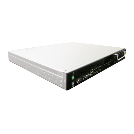
The MS-9228 1U Rackmount Server is a high-performance barebone ® ® ® system powered by Intel Pentium M Dothan processor, Intel ® 915GM, and Intel ICH6R chipsets. W ith high scalability, reliability, ease of use, and overall value, the MS-9228 makes an ideal choice for value conscious customers. -
Page 11: System Overview
MS-9228 1U Rackmount Server System Overview This section shows the configuration of the MS-9228 from different angles, and the connectors and buttons on the front and back panel. Top View HDD Tray PCI Riser Card Bracket CPU Socket Memory DIMM Slots... -
Page 12: Front View
Getting Started Front View PCI Card Bracket HDD Tray AC Power Connector PS/2 Mouse/Keyboard Serial Port VGA Port USB Ports Gigabit LAN Jacks s 10/100 LAN Jack HDD LED Power LED Power Button... - Page 13 MS-9228 1U Rackmount Server Power Button This main power button is used to turn on or off the system. Power LED This indicator shows the power status of the system. It glows when the main power is turned on. LAN Status Indicators These LED indicators flash to show the activity status on LAN1, LAN2, and LAN3.
-
Page 14: Usb Port
Getting Started M ouse/Keyboard Connector USB Port SIGNAL -Data SIGNAL DESCRIPTION +Data Mouse/Keyboard Data Mouse/Keyboard data No connection Ground Serial Port Mouse/Keyboard Clock Mouse/Keyboard clock 1 2 3 4 5 No connection LAN Jack 6 7 8 9 SIGNAL SOUT Gigabit LAN Pin Definition SIGNAL DESCRIPTION... -
Page 15: System Specifications
† MS-9628 Micro ATX server board † Supports Intel ® ® Pentium M Dothan processor in 478-pin package † Up to 2MB L2 cache (For more information on compatible components, please visit http://www.msi. com.tw/program/products/server/svr/pro_svr_qvl.php) Chipset † Intel ® 915GM Northbridge ®... - Page 16 Getting Started Onboard LAN † 2 Intel ® 82573V 10/100/1000 Mbits/sec Gigabit Ethernet controllers † 1 Intel ® 82562GZ 10/100 Mbits/sec Fast Ethernet controller Power M anagement Features † W ake up on LAN (W OL), wake up on PCI †...
-
Page 17: Mainboard Layout
MS-9228 1U Rackmount Server Mainboard Layout T: Mouse SYSFAN2 B: Keyboard DIMM3 JPW2 Intel 915GM Ports Intel 82573V Gb LAN CPUFAN1 LAN Jacks Intel 82573V Gb LAN LAN Jack SYSFAN1 Intel 82562GZ 10/100 LAN BIOS PCI2 JFP1 Intel ICH6R J LP C1... -
Page 18: Msi Special Features
Getting Started MSI Special Features PC Alert™ III The PC Alert III is a utility you can find in the application CD. The utility is just like your PC doctor that can detect the following PC hard- ware status during real time operation: ö... -
Page 19: Chapter 2. System Hardware
MS-9228 in three sections. Mainboard Hardware details the hard- ware components on the mainboard. System Assembly illustrates how to assemble each component of the MS-9228. Rack M ounting describes the procedures for mounting the unit into the rack in details. -
Page 20: Mainboard Components Guide
MS-9228 1U Rackmount Server Mainboard Components Guide SYSFAN2, p.2-11 DIMM3/4, p.2-4 J6/J4/J5, I/O Ports, p.2-13/14 p.2-6 JPW2, p.2-5 CPU, p.2-3 ATX1, p.2-5 CPUFAN1, p.2-11 IDE1, p.2-9 SYSFAN1, p.2-11 J3, p.2-13 BIO S JFP1, p.2-11 PCI Slot, p.2-15 SATA1/2/3/4, p.2-10 CLR_CMOS1,... -
Page 21: Central Processing Unit: Cpu
If you do not have the heat sink and cooling fan, contact your dealer to purchase and install them before turning on the computer. For more information on compatible components, please visit http://www.msi.com. tw/program/products/server/svr/pro_svr_qvl.php . MSI Reminds You... -
Page 22: Memory
MS-9228 1U Rackmount Server Memory The mainboard provides two 240-pin non-ECC DDR-II 400/533 DIMMs and supports up to 2GB system memory. For more information on compatible components, please visit http://www.msi.com. tw/program/products/server/svr/pro_svr_qvl.php . DIMM4 (DDR-II 400/533) DIMM3 (DDR-II 400/533) Memory Population Rules This mainboard supports DDR-II 400/533 memory interface. -
Page 23: Power Supply
PWR OK 5VSB +12V +12V MSI Reminds You... 1. Maker sure that these two connectors are connected to adequate SSI power supplies to ensure stable operation of the mainboard. 2. Power supply of 350watts (and above) is highly recommended for system stability. -
Page 24: Back Panel
MS-9228 1U Rackmount Server Back Panel M ou se Gigabit LAN 10/100 LAN Keyboard COM Port VGA Port USB Ports Mouse Connector (Green) / Keyboard Connector (Purple) ® The mainboard provides a standard PS/2 mouse/keyboard connector for attaching a ®... -
Page 25: Serial Port
System Hardware Serial Port The mainboard offers one 9-pin male DIN connector as the serial port. The port is a 16550A high speed communication port that sends/receives 16 bytes FIFOs. You can attach a serial mouse or other serial devices directly to the connector. Pin Definition 1 2 3 4 5 SIGNAL... -
Page 26: Rj-45 Lan Jacks
MS-9228 1U Rackmount Server RJ-45 LAN Jacks The mainboard provides 3 standard RJ-45 jacks powered by † 2 Intel ® 82573V 10/100/1000 Mbits/sec Gigabit Ethernet controllers † 1 Intel ® 82562GZ 10/100 Mbits/sec Fast Ethernet controller. Pin assignments vary depending on the transfer rates: 10/100Mbps or 1000Mbps. -
Page 27: Connectors
IDE1 can connect a Master and a Slave drive. You must configure the second hard drive to Slave mode by setting the jumper accordingly. MSI Reminds You... If you install two hard disks on cable, you must configure the second drive to Slave mode by setting its jumper. -
Page 28: Serial Ata Connectors: Sata1, Sata2, Sata3, Sata4
MS-9228 1U Rackmount Server Serial ATA Connectors: SATA1, SATA2, SATA3, SATA4 This mainboard provides four high-speed Serial ATA interface ports. Each supports generation serial ATA data rates of 150 MB/s and is fully compliant with Serial ATA 1.0 specifications. Each Serial ATA connector can connect to 1 hard disk device. -
Page 29: Fan Power Connectors: Cpufan1, Sysfan1, Sysfan2
+1 2V SENSOR SENSOR CPUFAN1 SYSFAN1 SYSFAN2 MSI Reminds You... ® Please refer to the recommended CPU fans at Intel official website or consult the vendors for proper CPU cooling fan. Front Panel Connector: JFP1 The mainboard provides one front panel connector for electrical connection to the ®... -
Page 30: Jumpers
MS-9228 1U Rackmount Server Jumpers The motherboard provides the following jumpers for you to set the computer’s function. This section will explain how to change your motherboard’s function through the use of jumpers. Clear CMOS Jumper: CLR_CMOS1 There is a CMOS RAM on board that has a power supply from external battery to keep the data of system configuration. -
Page 31: Cpu Vcca Jumper: J6
System Hardware CPU VCCA Jumper: J6 This jumper controls the CPU VCCA supply voltage. VCCA = 1.8V VCCA = 1.5V GMCH Voltage Jumper: J3 This jumper is used to adjust the voltage of the Intel 915GM GMCH (Graphics and Memory Controller Hub) as a way to enhance graphics performance. } 1.05V for add-on VGA card } 1.05V for onboard Intel 915GM Short Pin #1-2... -
Page 32: Fsb Frequency Jumpers: J4, J5
MS-9228 1U Rackmount Server FSB Frequency Jumpers: J4, J5 These two jumpers specify the FSB frequency of the onboard CPU. To ensure system stability, make sure that these jumpers are properly set to correspond with your CPU’s FSB frequency. Dothan B... -
Page 33: Slot
PCI (Peripheral Component Interconnect) Slot The mainboard provides one 32-bit Master PCI slot. PCI2: 32-bit/33MHz PCI slot MSI Reminds You... When adding or removing expansion cards, make sure that you un- plug the power supply first. Meanwhile, read the documentation for... -
Page 34: System Assembly Flowchart
MS-9228 1U Rackmount Server System Assembly Flowchart The following flowchart shows basic system assembly procedures. Please note that always wear anti-static gloves when handling electrical components and exercise caution during the installation process. For more information, contact your local dealer or experienced technician. - Page 35 System Hardware REPLACE RISER CARD BRACKET INSTALL HARD DISK DRIVES CONNECT HDD & POWER CORDS CHECK IF ALL PARTS ARE PROPERLY CONNECTED REPLACE CHASSIS COVER FINISH 2-17...
-
Page 36: System Assembly
MS-9228 1U Rackmount Server System Assembly Removing the Chassis Cover 1. Slide the chassis cover backwards. 2. Lift the cover up from the chassis. 2-18... -
Page 37: Replacing The Chassis Cover
1. Replace the chassis cover. 2. Slide the cover forwards and make sure the safety lock fits firmly. MSI Reminds You... Before you remove or install any components, make sure the server is not turned on or connected to the AC power. -
Page 38: Cpu & Heatsink
MS-9228 1U Rackmount Server CPU & Heatsink 1. Locate the CPU socket. 2. Locate the gold arrow on the CPU. 3. On the front end of the CPU socket is a locking mechanism designed into the form of a screw head. Make sure that you deactuate this mechanism with a screwdriver before installing the CPU. -
Page 39: System Hardware
8. Loosen the metal clips for heatsink installation. 9. Flip over the cooler set (fan & heatsink bundled) and detach the shield of the backplate’s paster. MSI Reminds You... The heatsink has to be installed to prevent the CPU from overheating. 2-21... - Page 40 MS-9228 1U Rackmount Server 10. Mount the cooler set (fan & heatsink bundled) on top of the CPU and fit it into the retention mechanism. 11. Press the clips into the hooks to se- cure the cooler set in place.
-
Page 41: Ddr-Ii Memory
2. For optimal system performance, at least two memory modules must be installed. Slot Combination 1 Combination 2 Combination 3 DIMM3 64MB~1GB DIMM4 64MB~1GB Total Memory 128MB~2GB MSI Reminds You... For more information on compatible components, please visit http:// www.msi.com.tw/program/products/server/svr/pro_svr_qvl.php . 2-23... -
Page 42: Pci Expansion Card
MS-9228 1U Rackmount Server PCI Expansion Card 1. Unscrew the riser card bracket on 2. Lift the bracket up from the chassis. the chassis. 3. Unscrew the cover plate and put it aside for later use. 2-24... - Page 43 System Hardware 4. Insert the expansion card into the PCI slot on the riser card. 5. S c r ew t h e exp an s i on c ar d firmly to the riser card bracket. 6. Replace the riser card bracket to the chassis. Align the riser card golden fingers with the onboard PCI slot.
-
Page 44: Hard Disk Drives
MS-9228 1U Rackmount Server Hard Disk Drives 1. Locate the HDD tray and unscrew it. 2. Pull it out from the chassis. 3. On the sides of the tray are eight screw sets, four on each side. Each screw set has one screw inserted beforehand for easy installation. - Page 45 System Hardware 4. Place the HDD into the tray and align the screw holes on the HDD with the ones on the tray. 5. Srew the HDD firmly to the tray. 6. Follow the same procedures to install the second HDD. 2-27...
- Page 46 MS-9228 1U Rackmount Server 7. Insert the HDD tray into the bay and push it back in place. The HDD power cord and the ATA100 cable will be automatically connected. 8. Screw the HDD set securely back to the system.
-
Page 47: Rack Mounting
System Hardware Rack Mounting Chassis Ears Screw the chassis ears to both sides of the chassis (as marked below). 2-29... -
Page 48: Chassis Rails
MS-9228 1U Rackmount Server Chassis Rails 1. Pull the inner rails out. 2. As semble the inner rails to the chassis. 2-30... - Page 49 System Hardware 3. Mount the L-shaped bracket onto the outer rail. 4. Mount the slides to the vertical racks. M4 Nut M4 Screw M4 Screw Front 2-31...
-
Page 50: Chassis Into/Off The Rack
MS-9228 1U Rackmount Server Chassis into/off the Rack 1. Locate the triangle marks on the rack and screw the rail to the rack as shown. 2. To slide the system into the rack, first align the chassis rails with the rack rails and push the system backwards until it reaches the end. -
Page 51: Chapter 3. Bios Setup
SETUP. ² You want to change the default settings for customized features. MSI Reminds You... 1. The items under each BIOS category described in this chapter are under continuous update for better system performance. -
Page 52: Entering Setup
MS-9228 1U Rackmount Server Entering Setup Power on the computer and the system will start POST (Power On Self Test) process. W hen the message below appears on the screen, press <F1> key to enter Setup. Press F1 to enter SETUP, <F12> to enter Boot Menu If the message disappears before you respond and you still wish to enter Setup, restart the system by turning it OFF and On or pressing the RESET button. -
Page 53: Getting Help
BIOS Setup Getting Help After entering the Setup menu, the first menu you will see is the Main Menu. M ain M enu The main menu lists the setup functions you can make changes to. You can use the arrow keys ( to select the item. -
Page 54: The Menu Bar
MS-9228 1U Rackmount Server The Menu Bar Once you enter Phoenix-AwardBIOS CM OS Setup Utility, the Main Menu will appear on the screen. On the Main Menu screen, you will see basic BIOS settings including system time & date, and the setup categories the BIOS supplies. Use Arrow keys to move among the items and menus, and make changes to the settings. -
Page 55: Main
BIOS Setup Main The items inside the Main menu are for basic system information and configuration. Each item includes none, one or more setup items. Use the Up/Down arrow keys or <Tab> to highlight the item or field you want to modify and use the <+> or <-> key to switch to the value you prefer. - Page 56 MS-9228 1U Rackmount Server provided in the documentation from your hard disk vendor or the system manufacturer. Access M ode The settings are CHS, LBA, Large, Auto. Capacity The formatted size of the storage device. Cylinder Number of cylinders. Head Number of heads.
-
Page 57: Advanced
BIOS Setup Advanced Items in the menu are divided into several sub-menus. Each sub-menu provides more settings. To enter the sub-menu, highlight the sub-menu you want to configure and press <Enter>. Fan Speed Control The sub-menu is used to control fan speeds for optimal system performance. Smart CPU Fan/ SYS Fan1/ SYS Fan2 Temp. - Page 58 MS-9228 1U Rackmount Server CPU Fan/ SYS Fan1/ SYS Fan2 Tolerance Value You can select a fan tolerance value here for the specific range for the Smart CPU Fan/ SYS Fan1/ SYS Fan2 Temp. items. If the current temperatures of the fans reach to the maximum threshold (the temperatures set in the Smart CPU Fan/ SYS Fan1/ SYS Fan2 Temp.
- Page 59 BIOS Setup DRAM RAS# Precharge This item controls the number of cycles for Row Address Strobe (RAS) to be allowed to precharge. If insufficient time is allowed for the RAS to accumulate its charge before DRAM refresh, refresh may be incomplete and DRAM may fail to retain data.
- Page 60 MS-9228 1U Rackmount Server SATA Mode This setting specifies the operation mode of SATA devices. Setting options: [IDE], [RAID]. On-Chip Serial ATA This setting specifies the function of the on-chip SATA controller. [Disabled] Disable SATA controller [Auto] Automatically determined by BIOS [Combined Mode] SATA and PATA are combined, max.
- Page 61 BIOS Setup Ethernet 1 Controller This setting disables/enables the onboard Ethernet controller. Option ROM Control The items enable or disable the initialization of the onboard LAN Boot ROMs during bootup. Selecting [Disabled] will speed up the boot process. PCI Slot 1 Device Press <Enter>...
- Page 62 MS-9228 1U Rackmount Server Super IO Device Press <Enter> to enter the sub-menu and the following screen appears: Onboard Serial Port 1 Select an address and corresponding interrupt for Serial Port 1. The settings are: [3F8/IRQ4], [2E8/IRQ3], [3E8/IRQ4], [2F8/IRQ3], [Disabled], [Auto].
- Page 63 BIOS Setup [Instant-Off] The power button functions as a normal power-on/-off button. [Delay 4 Sec.] W hen you press the power button, the computer enters the suspend/sleep mode, but if the button is pressed for more than four seconds, the computer is turned off. Wake Up On LAN This setting specifies whether the system will be awakened from power sav- ing modes when activity or input signal of LAN is detected.
- Page 64 MS-9228 1U Rackmount Server CPU Feature Press <Enter> to view the settings of the onboard CPU(s). Delay Prior to Thermal W hen the CPU temperature reaches a factory preset level, a thermal monitoring mechanism will be enabled following the appropriate timing delay specified in this field.
- Page 65 BIOS Setup MPS Version Control For OS This field allows you to select which MPS (Multi-Processor Specification) version to be used for the operating system. You need to select the MPS version supported by your operating system. To find out which version to use, consult the vendor of your operating system.
-
Page 66: Security
MS-9228 1U Rackmount Server Security This section lets you set security passwords to control access to the system at boot time and/or when entering the BIOS setup program. Set Supervisor Password Supervisor Password controls access to the BIOS Setup utility. -
Page 67: Server
BIOS Setup Server This section shows the overall hardware specifications of your system. System Summary Press <Enter> to view the hardware specifications of your system. AC-LINK AC-link is a unique, elegant control scheme that uses reliable, rugged SCRs to create clean power waveforms. - Page 68 MS-9228 1U Rackmount Server Halt On The setting determines whether the system will stop if an error is detected at boot. W hen the system stops for the errors preset, it will halt on for 15 seconds and then automatically resume its operation. Available options are: [All Errors] The system stops when any error is detected.
-
Page 69: Boot
BIOS Setup Boot Use this menu to arrange and specify the priority of the devices from which the BIOS will attempt to boot the Operating System. Removable Device/ Hard Disk/ Network Boot Priority These settings allow users to set the priority of the specified devices. First press <Enter>... -
Page 70: Exit
MS-9228 1U Rackmount Server Exit The following sections describe each of the options on this menu. Note that <Esc> does not exit this menu. You must select one of the items from the menu or menu bar to exit. Load Fail-Safe Defaults Use this menu to load the default values set by the BIOS vendor for stable system performance. -
Page 71: Appendix A: Intel Ich6R Sata Raid (Optional
Intel Matrix RAID Technology is the advanced ability for two RAID volumes to share the combined space of two hard drives being used in unison. MSI Reminds You... The maximum number of hard drives for RAID 0, RAID 1 or Matrix mode is 2. -
Page 72: Bios Configuration
MS-9228 1U Rackmount Server BIOS Configuration The Intel RAID Option ROM should be integrated with the system BIOS on all motherboards with a supported Intel chipset. The Intel RAID Option ROM is the Intel RAID implementation and provides BIOS and DOS disk services. Please use <Ctrl> + <I>... - Page 73 Intel ICH6R SATA RAID After pressing the <Ctrl> and <I> keys simultaneously, the following window will appear: (1) Create RAID Volume Select option 1 “Create RAID Volume” and press <Enter> key. The following screen appears. Then in the Name field, specify a RAID Volume name and then press the <TAB>...
- Page 74 MS-9228 1U Rackmount Server In the Disk field, press <Enter> key and the following screen appears. Use <Space> key to select the disks you want to create for the RAID volume, then click <Enter> key to finish selection. Then select the strip value for the RAID 0 or RAID 1 array by using the “upper arrow”...
- Page 75 Intel ICH6R SATA RAID MSI Reminds You... Since you want to create two volumes (Intel Matrix RAID Technology), this default size (maximum) needs to be reduced. Type in a new size for the first volume. As an example: if you want the first volume to span the first half of the two disks, re-type the size to be half of what is shown by default.
- Page 76 MS-9228 1U Rackmount Server (2) Delete RAID Volume Here you can delete the RAID volume, but please be noted that all data on RAID drives will be lost. MSI Reminds You... If your system currently boots to RAID and you delete the RAID volume in the Intel RAID Option ROM, your system will become unbootable.
- Page 77 RAID volume and remove any RAID structures from the drives. The following screen appears: Press <Y> key to accept the selection. MSI Reminds You... 1. You will lose all data on the RAID drives and any internal RAID structures when you perform this operation.
-
Page 78: Installing Software
Windows XP/2003 installation. † Existing Windows XP/2003 Driver Installation 1. Insert the MSI application CD into the CD-ROM drive. 2. The CD will auto-run and the setup screen will appear. 3. Under the Driver tab, click on Intel IAA RAID Edition. -
Page 79: Installation Of Intel Matrix Stroage Console
For this reason, you cannot remove or un-install this driver from the system after installation; however, you will have the ability to un-install all other non-driver components. Insert the MSI application CD and click on the Intel IAA RAID Edition to install the s of tware. Click on this item... - Page 80 MS-9228 1U Rackmount Server The InstallShield Wizard will begin automatically for installation showed as following: Click on the Next button to proceed the installation in the welcoming window. A-10...
- Page 81 Intel ICH6R SATA RAID The window shows the components to be installed. Click Next button to continue. After reading the license agreement in the following window, click Yes button to continue. A-11...
- Page 82 MS-9228 1U Rackmount Server Select the folder in which you want the program to be installed in the following window, and click Next button to start installation. Select a program folder in the following window where you want Setup to add the program icon.
- Page 83 Intel ICH6R SATA RAID The following window appears to show the Intel Application Accelerator RAID Edition Setup installation status. Once the installation is complete, the following window appears. Click Finish, and restart the system. A-13...
-
Page 84: Raid Migration Instructions
MS-9228 1U Rackmount Server RAID Migration Instructions The Intel Matrix Storage Console offers the flexibility to upgrade from a single Serial ATA (SATA) hard drive to RAID configuration when an additional SATA hard drive is added to the system. This process will create a new RAID volume from an existing disk. -
Page 85: Create Raid Volume From Existing Disk
Intel ICH6R SATA RAID Create RAID Volume from Existing Disk To create a RAID volume from an existing disk, choose Action --> Create RAID Volume from Existing Hard Drive. The Create RAID Volume from Existing Hard Drive Wizard pops up to lead you for the following procedure. - Page 86 MS-9228 1U Rackmount Server (1) Step 1: Configure Volume Here you can configure the new RAID volume by entering the volume name, selecting the RAID level and strip size. † RAID Volume Name: A desired RAID volume name needs to be typed in where the ‘RAID_Volume1’ text currently appears above.
- Page 87 Intel ICH6R SATA RAID are similar to RAID-0 reads, writes can be either rather expensive (requiring read-in prior to write, in order to be able to calculate the correct parity information), or similar to RAID-1 writes. The write efficiency depends heavily on the amount of memory in the machine, and the usage pattern of the array.
- Page 88 MS-9228 1U Rackmount Server (3) Select Member Hard Drive(s) Then select the member disk (the target disk) that you wish to use and then click “--->” to move it to the Selected field. Then click Next to continue. Please note that the existing data on the selected hard drive(s) will be deleted permanently.
- Page 89 Intel ICH6R SATA RAID (4) Specify Volume Size Specify the amount of available array space to be used by the new RAID volume. You may enter the amount in the space or use the slider to specify. It is recom- mended you use 100% of the available space for the optimized usage.
- Page 90 MS-9228 1U Rackmount Server (6) Start Migration The migration process may take up to two hours to complete depending on the size of the disks being used and the strip size selected. A dialogue window will appear stating that the migration process may take considerable time to complete, meanwhile a popup dialogue at the taskbar will also show the migration status.
Need help?
Do you have a question about the MS-9228 and is the answer not in the manual?
Questions and answers