Table of Contents
Advertisement
Quick Links
Advertisement
Table of Contents

Related Manuals for MSI MS-9232


Summary of Contents for MSI MS-9232
- Page 1 MS-9232 1U Rackmount Ser ver G52-92321X1...
-
Page 2: Trademarks
Alternatively, please try the following help resources for further guidance. Visit the MSI website at http://www.msi.com.tw/program/service/faq/ faq/esc_faq_list.php for FAQ, technical guide, BIOS updates, driver updates, and other information. Contact our technical staff at http://support.msi.com.tw/. -
Page 3: Safety Instructions
Safety Instructions Always read the safety instructions carefully. Keep this User’s Manual for future reference. Keep this equipment away from humidity. Lay this equipment on a reliable flat surface before setting it up. The openings on the enclosure are for air convection hence protects the equip- ment from overheating. -
Page 4: Fcc-B Radio Frequency Interference Statement
VOIR LA NOTICE D’INSTALLATION AVANT DE RACCORDER AU RESEAU. Micro-Star International MS-9232 This device complies with Part 15 of the FCC Rules. Operation is subject to the following two conditions: (1) this device may not cause harmful interference, and (2) this device must accept any interference received, including interference that may cause undesired operation. -
Page 5: Weee (Waste Electrical And Electronic Equipment) Statement
WEEE (Waste Electrical and Electronic Equipment) Statement... -
Page 8: Table Of Contents
Chapter 1 Getting Started ..................1-1 System Overview ....................1-2 Mainboard Specifications ................... 1-6 Mainboard Layout ....................1-8 MSI Special Feature .................... 1-8 Core Center (Optional) ................1-9 Chapter 2 Hardware Setup ..................2-1 Quick Components Guide ..................2-2 CPU (Central Processing Unit) ................2-3 Memory ......................... - Page 9 System Assembly ....................2-14 Removing the Chassis Cover ..............2-15 Replacing the Chassis Cover ..............2-16 CPU & Cooler Set Installation ..............2-17 DDR-II Memory .................... 2-19 PCI Expansion Card ................... 2-20 Hard Disk Drives ..................2-22 Rock Mounting ....................2-24 Chassis Ears .....................
-
Page 11: Chapter 1 Getting Started
Intel Core Duo/ ® Core Solo/Celeron M processor, Intel ® 945GT, and Intel ® ICH7R chipsets. W ith high scalability, reliability, ease of use, and overall value, the MS-9232 makes an ideal choice for value conscious customers. -
Page 12: System Overview
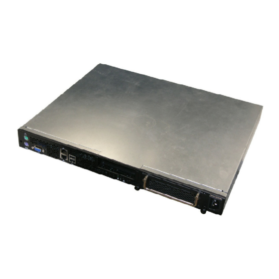
M S-9232 Server System Overview This section shows the configuration of the MS-9232 from different angles, and the connectors and buttons on the front and back panel. Top View Front Back HDD Tray PCI Riser Card Bracket CPU Socket Memory DIMM Slots... -
Page 13: Front View
Getting Started Front View PCI Card Bracket HDD Tray AC Power Connector PS/2 Mouse/Keyboard VGA Port USB Ports Gigabit LAN Jacks s HDD LED Power LED Power Button... - Page 14 M S-9232 Server Power Button This main power button is used to turn on or off the system. Power LED This indicator shows the power status of the system. It glows when the main power is turned on. LAN Status Indicators These LED indicators flash to show the activity status on LAN1 and LAN2.
-
Page 15: Getting Started
Getting Started M ouse/Keyboard Connector USB Port SIGNAL -Data SIGNAL DESCRIPTION +Data Mouse/Keyboard Data Mouse/Keyboard data No connection Ground Mouse/Keyboard Clock Mouse/Keyboard clock No connection LAN Jack VGA Port Gigabit LAN Pin Definition SIGNAL SIGNAL DESCRIPTION GREEN Differential Pair 0+ BLUE Differential Pair 0- Differential Pair 1+... -
Page 16: Mainboard Specifications
M S-9232 Server Mainboard Specifications Processor Support - Intel Core Duo/Core Solo/Celeron M CPU in the 478 package ® - Supports 3/4 pin CPU Fan Pin-Header with Fan Speed Control - Supports Intel Dual Core Technology to 533/667MHz and up Supported FSB - 533/667MHz Chipset... - Page 17 - Low profile slot x 1 - Chassis Dimension: 432mm (W ) X 355mm (L) X 42.5mm (H) Power Supply - Input: 90-135/180-265Vac, Auto-Range - Output: Maximum Power 200 W atts For more information on compatible components, please visit http://www.msi.com.tw/program/products/server/svr/pro_svr_qvl.php...
-
Page 18: Mainboard Layout
M S-9232 Server Mainboard Layout Top: Mouse Bo tt om: Keybo ard FDD 1 ATX1 JPW2 COM1 DIMM1 VGA Port DI MM 2 JPW 1 JCI2 Intel 825 73L Intel 9 45 GT LAN Ja cks Intel 82573 L USB Po rts PCI-E1 SYSFAN1 PCI3... -
Page 19: Msi Special Feature
Getting Started MSI Special Feature Core Center (Optional) The Core Center is a new utility you can find in the application CD. The utility is just like your PC doctor that can detect, view and adjust the PC hardware and system status during real time operation. - Page 20 M S-9232 Server Left-side: Current system status In the left sub-menu, you can configure the settings of FSB & DOT by clicking the radio button in front of each item and make it available (the radio button will be lit as yellow when selected), use the “+”...
-
Page 21: Chapter 2 Hardware Setup
Mainboard Hardware CPU, Memory, Power Supply, Back Panel, Connectors, Jumpers, Slot Chassis Cover CPU, Heatsink System Assembly Memory Riser Card MS-9232 Hard Disk Drives Chassis Ears and Rails Rack Rails Rack Mounting Chassis into the Rack Chassis off the Rack... -
Page 22: Quick Components Guide
M S-9232 Server Quick Components Guide DDRII DIMMs, FDD1, p.2-7 ATX1, p.2-4 p.2-10 COM1,p.2-10 JCI2, p.2-10 JPW2, p.2-6 JPW1, p.2-10 I/O Panel IDE1, p.2-7 CPUFAN1/ SYSFAN2, p.2-9 CPU, p.2-3 PCI-E Slot, SYSFAN1, p.2-12 p.2-9 PCI Slots, JLPC1, BIOS p.2-12 p.2-10 JFP1, p.2-9 SATA1~SATA4,... -
Page 23: Cpu (Central Processing Unit)
If you do not have the heat sink and cooling fan, contact your dealer to purchase and install them before turning on the computer. For more information on compatible components, please visit http://www.msi.com. tw/program/products/server/svr/pro_svr_qvl.php . Important 1. -
Page 24: Memory
M S-9232 Server Memory The mainboard provides two 240-pin non-ECC DDRII 533/667 DIMMs and supports up to 4GB system memory. For more information on compatible components, please visit http://www.msi.com. tw/program/products/server/svr/pro_svr_qvl.php. DDRII 240-pin, 1.8V 64x2=128 pin 56x2=112 pin Single-Channel: All DIMMs in GREEN Memory Population Rules This mainboard supports DDRII 533/667 memory interface. -
Page 25: Installing Ddrii Modules
Hardware Setup Installing DDRII Modules 1. The memory module has only one notch on the center and will only fit in the right orientation. 2. Insert the DIMM memory module vertically into the DIMM slot. Then push it in until the golden finger on the memory module is deeply inserted in the socket. -
Page 26: Power Supply
M S-9232 Server Power Supply SSI 24-Pin System Power Connector: ATX1 This connector allows you to connect an SSI power supply. To connect the SSI power supply, make sure the plug of the power supply is inserted pin 13 in the proper orientation and the pins are aligned. Then push down the power supply firmly into the connector. -
Page 27: Floppy Disk Drive Connector: Fdd1
Hardware Setup Connectors Floppy Disk Drive Connector: FDD1 This standard FDD connector supports 360K, 720K, 1.2M, 1.44M and 2.88M floppy disk types. FDD1 ATA100 Hard Disk Connector: IDE1 The mainboard has a 32-bit Enhanced PCI IDE and Ultra DMA 66/100 controller that provides PIO mode 0~4, Bus Master, and Ultra DMA 66/100 function. -
Page 28: Serial Ata Connectors: Sata1~4
M S-9232 Server Serial ATA Connectors: SATA1~4 SATA1~SATA4 are high-speed SATA II interface ports and support SATA II data rates of 300MB/s. Each SATA II connector can connect to 1 hard disk device and is fully compliant with Serial ATA 2.0 specifications. Please refer to the Appendix ICH7R RAID for detailed application. -
Page 29: Front Panel Connectors: Jfp1
Hardware Setup Front Panel Connectors: JFP1 The mainboard provides one front panel connector for electrical connection to the front panel switches and LEDs. The JFP1 is compliant with Intel ® Front Panel I/O Connectivity Design Guide. JFP1 Power Power Reset Switch Switch JFP1 Pin Definition... -
Page 30: Chassis Intrusion Switch Connector: Jci2
M S-9232 Server Chassis Intrusion Switch Connector: JCI2 This connector connects to a 2-pin chassis switch. If the chassis is opened, the switch will be short. The system will record this status and show a warning mes- sage on the screen. To clear the warning, you must enter the BIOS utility and clear the record. -
Page 31: Jumpers
Hardware Setup Jumpers Clear CMOS Jumper: CLR_CMOS1 There is a CMOS RAM onboard that has a power supply from external battery to keep the data of system configuration. With the CMOS RAM, the system can automatically boot OS every time it is turned on. If you want to clear the system configuration, set the CLR_CMOS1 (Clear CMOS Jumper ) to clear data. -
Page 32: Pci (Peripheral Component Interconnect) Express Slot
M S-9232 Server Slots PCI (Peripheral Component Interconnect) Express Slot PCI Express architecture provides a high performance I/O infrastructure for Desktop Platforms with transfer rates starting at 2.5 Giga transfers per second over a PCI Express x1 lane for Gigabit Ethernet, TV Tuners, 1394 controllers, and general pur- pose I/O. -
Page 33: System Assembly Flowchart
Hardware Setup System Assembly Flowchart The following flowchart shows basic system assembly procedures. Please note that always wear anti-static gloves when handling electrical components and exer- cise caution during the installation process. For more information, contact your local dealer or experienced technician. START REMOVE CHASSIS COVER INSTALL... - Page 34 M S-9232 Server REPLACE RISER CARD BRACKET INSTALL HARD DISK DRIVES CONNECT HDD & POWER CORDS CHECK IF ALL PARTS ARE PROPERLY CONNECTED REPLACE CHASSIS COVER FINISH 2-14...
-
Page 35: System Assembly
Hardware Setup System Assembly Removing the Chassis Cover 1. Slide the chassis cover backwards. 2. Lift the cover up from the chassis. 2-15... -
Page 36: Replacing The Chassis Cover
M S-9232 Server Replacing the Chassis Cover 1. Replace the chassis cover. 2. Slide the cover forwards and make sure the safety lock fits firmly. Important Before you remove or install any components, make sure the server is not turned on or connected to the AC power. 2-16... -
Page 37: Cpu & Cooler Set Installation
Hardware Setup CPU & Cooler Set Installation 1. Place the CPU on top of the socket. Make sure to align the gold arrow on the CPU with the arrow key on the socket. 2. Push the CPU down until its pins securely fit into the socket. 3. - Page 38 M S-9232 Server 5. Mount the cooler set (fan & heatsink bundled) on top of the CPU and fit it into the retention mechanism. 7. Connect the fan power cable from the 6. Secure the metal clips back to the mounted fan to the 3-pin fan power con- retention mechanism.
-
Page 39: Slots
The plastic clip at each side of the DIMM slot will automatically close. 2. For optimal system performance, at least two memory modules must be installed. Important For more information on compatible components, please visit http://www. msi.com.tw/program/products/server/svr/pro_svr_qvl.php . 2-19... -
Page 40: Pci Expansion Card
M S-9232 Server PCI Expansion Card 1. Unscrew the riser card bracket on 2. Lift the bracket up from the chassis. the chassis. 3. Unscrew the cover plate and put it aside for later use. 2-20... - Page 41 Hardware Setup 4. Insert the expansion card into the PCI slot on the riser card. 5. S c r ew t h e exp an s i on c ar d firmly to the riser card bracket. 6. Replace the riser card bracket to the chassis. Align the riser card golden fingers with the onboard PCI slot.
-
Page 42: Hard Disk Drives
M S-9232 Server Hard Disk Drives 1. Locate the HDD tray and unscrew it. 2. Pull it out from the chassis. 3. On the sides of the tray are eight screw sets, four on each side. Each screw set has one screw inserted beforehand for easy installation. 2-22... - Page 43 Hardware Setup 4. Place the HDD into the tray and align the screw holes on the HDD with the ones on the tray. 5. Srew the HDD firmly to the tray. 6. Follow the same procedures to install the second HDD. 2-23...
- Page 44 M S-9232 Server 7. Insert the HDD tray into the bay and push it back in place. The HDD power cord and the SATA cable will be automatically connected. 8. Screw the HDD set securely back to the system. 2-24...
-
Page 45: Rock Mounting
Hardware Setup Rock Mounting Chassis Ears Screw the chassis ears to both sides of the chassis (as marked below). Chassis Rails 1. Pull the inner rails out. 2. As semble the inner rails to the chassis. 2-25... - Page 46 M S-9232 Server 3. Mount the L-shaped bracket onto the outer rail. 4. Mount the slides to the vertical racks. M4 Nut M4 Screw M4 Screw Front 2-26...
-
Page 47: Chassis Into/Off The Rack
Hardware Setup Chassis into/off the Rack 1. Locate the triangle marks on the rack and screw the rail to the rack as shown. 2. To slide the system into the rack, first align the chassis rails with the rack rails and push the system backwards until it reaches the end. - Page 48 M S-9232 Server 2-28...
-
Page 49: Chapter 3 Bios Setup
BIOS Setup Chapter 3 BIOS Setup This chapter provides information on the BIOS Setup program and allows you to configure the system for optimum use. You may need to run the Setup program when: ² An error message appears on the screen during the system booting up, and requests you to run SETUP. -
Page 50: Entering Setup
M S-9232 Server Entering Setup Power on the computer and the system will start POST (Power On Self Test) process. W hen the message below appears on the screen, press <F1> key to enter Setup. Press F1 to enter SETUP If the message disappears before you respond and you still wish to enter Setup, restart the system by turning it OFF and On or pressing the RESET button. -
Page 51: Control Keys
BIOS Setup Control Keys Move to the previous item < > Move to the next item < > Move to the item in the left hand < > Move to the item in the right hand < > Select the item <Enter>... -
Page 52: The Menu Bar
M S-9232 Server The Menu Bar Main Use this menu for basic system configurations, such as time, date etc. Advanced Use this menu to set up the items of special enhanced features available on your system’s chipset. PC Health This entry monitors your hardware health status. Security Use this menu to set Supervisor and User Passwords. - Page 53 BIOS Setup Main Date (mm:dd:yy) The date format is <Day>, <Month> <Date> <Year>. T ime (hh:mm:ss) The time format is <Hour> <Minute> <Second>. IDE Channel 0/1 Master/Slave Press PgUp/<+> or PgDn/<-> to select [Manual], [None] or [Auto] type. Note that the specifications of your drive must match with the drive table.
- Page 54 M S-9232 Server Drive A This item allows you to set the type of floppy drives installed. Base/Extended/Total M emory The three items show the memory status of the system. (Read-only)
-
Page 55: Advanced
BIOS Setup Advanced Advanced BIOS Features The sub-menu is used to configure chipset features for optimal system performance. Quick Power On Self Test Select [Enabled] to reduce the amount of time required to run the power-on self- test (POST). A quick POST skips certain steps. We recommend that you nor- mally disable quick POST. - Page 56 M S-9232 Server DRAM Timing Selectable Selects whether DRAM timing is controlled by the SPD (Serial Presence Detect) EEPROM on the DRAM module. Setting to [By SPD] enables DRAM timing to be determined automatically by BIOS based on the configurations on the SPD. Selecting [Manual] allows users to configure the following fields manually.
- Page 57 BIOS Setup IDE Primary Master/Slave PIO The IDE PIO (Programmed Input/Output) fields let you set a PIO mode for the IDE devices that the onboard IDE interface supports. Modes 0 through 4 provide successively increased performance. In [Auto] mode, the system automatically determines the best mode for each device.
- Page 58 M S-9232 Server USB 2.0 Controller This setting is used to enable/disable the onboard USB 2.0 controller. USB Keyboard/M ouse Support Set to [Enabled] if your need to use a USB-interfaced keyboard/mouse in the operating system that does not support or have any USB driver installed, such as DOS and SCO Unix.
- Page 59 BIOS Setup [Delay 4 Sec.] W hen you press the power button, the computer enters the suspend/sleep mode, but if the button is pressed for more than four seconds, the computer is turned off. Wake-Up By PCI Card W hen setting to [Enabled], this setting allows your system to be awakened from the power saving modes through any event on PCI PME (Power Man- agement Event).
-
Page 60: Pc Health
M S-9232 Server PC Health Smart Fan Setting The sub-menu is used to control fan speeds for optimal system performance. Smart CPUFan1 / SYSFan1 / SYSFan2 Temperature Select a temperature setting here, and if the temperature of the CPU/system climbs up to the selected temperature setting, the system will automatically increase the speed of the CPU/system fan to cool down the overheated CPU/ system. -
Page 61: Security
BIOS Setup Security Set Supervisor Password Supervisor Password controls access to the BIOS Setup utility. Set User Password User Password controls access to the system at boot. Security Option This specifies the type of BIOS password protection that is implemented. Settings are described below: Option Description... -
Page 62: System
M S-9232 Server System Sy stem Summary Press <Enter> to view the hardware specifications of your system. Halt On The setting determines whether the system will stop if an error is detected at boot. W hen the system stops for the errors preset, it will halt on for 15 seconds and then automatically resume its operation. -
Page 63: Boot
BIOS Setup Boot Hard Disk Boot Priority These settings allow users to set the priority of hard disk drives. First press <Enter> to enter the sub-menu. Then you may use the arrow keys ( ) to select the desired device, then press <+>, <-> or <PageUp>, <PageDown> key to move it up/down in the priority list. -
Page 64: Exit
M S-9232 Server Exit Load Fail-Safe Defaults Use this menu to load the default values set by the BIOS vendor for stable system performance. Load Optimized Defaults Use this menu to load the default values set by the mainboard manufacturer specifi- cally for optimal performance of the mainboard. -
Page 65: Appendix A Intel Ich7R Sata Raid
Intel ICH7R SATA RAID Appendix A Intel ICH7R SATA RAID The ICH7R provides a hybrid solution that combines four independent SATAII ports for support of up to four Serial ATAII (Serial ATAII RAID) drives. It offers RAID level 0 (Striping), RAID level 1 (Mirroring and Duplexing), RAID level 5 (Block Interleaved Distrib- uted Parity), RAID level 10 (A Stripe of Mirrors) and Intel... -
Page 66: Ich7R Introduction
M S-9232 Server ICH7R Introduction The ICH7R provides a hybrid solution that combines four independent SATAII ports for support of up to four Serial ATAII (Serial ATAII RAID) drives. Serial ATAII (SATAII) is the latest generation of the ATA interface. SATA hard drives deliver blistering transfer speeds up to 300MB/sec. -
Page 67: Bios Configuration
Intel ICH7R SATA RAID BIOS Configuration The Intel Matrix Storage Manager Option ROM should be integrated with the system BIOS on all motherboards with a supported Intel chipset. The Intel Matrix Stroage Manager Option ROM is the Intel RAID implementation and provides BIOS and DOS disk services. - Page 68 M S-9232 Server After pressing the <Ctrl> and <I> keys simultaneously, the following window will appear: (1) Create RAID Volume Select option 1 “Create RAID Volume” and press <Enter> key. The following screen appears. Then in the Name field, specify a RAID Volume name and then press the <TAB>...
- Page 69 Intel ICH7R SATA RAID In the Disk field, press <Enter> key and the following screen appears. Use <Space> key to select the disks you want to create for the RAID volume, then click <Enter> key to finish selection. Then select the strip value for the RAID array by using the “upper arrow” or “down arrow”...
- Page 70 M S-9232 Server Important Since you want to create two volumes (Intel Matrix RAID Technology), this default size (maximum) needs to be reduced. Type in a new size for the first volume. As an example: if you want the first volume to span the first half of the two disks, re-type the size to be half of what is shown by default.
- Page 71 Intel ICH7R SATA RAID (2) Delete RAID Volume Here you can delete the RAID volume, but please be noted that all data on RAID drives will be lost. Important If your system currently boots to RAID and you delete the RAID volume in the Intel RAID Option ROM, your system will become unbootable.
- Page 72 M S-9232 Server (3) Reset Disks to Non-RAID Select option 3 Reset Disks to Non-RAID and press <Enter> to delete the RAID volume and remove any RAID structures from the drives. The following screen appears: Press <Y> key to accept the selection. Important 1.
-
Page 73: Installing Software
Windows XP/2000 installation. † Existing Windows XP/2000 Driver Installation 1. Insert the MSI CD into the CD-ROM drive. 2. The CD will auto-run and the setup screen will appear. 3. Under the Driver tab, click on Intel IAA RAID Edition. -
Page 74: Installation Of Intel Matrix Storage Console
For this reason, you cannot remove or un-install this driver from the system after installation; however, you will have the ability to un-install all other non-driver components. Insert the MSI CD and click on the Intel IAA RAID Edition to install the software. Click on this item A-10... - Page 75 Intel ICH7R SATA RAID The InstallShield Wizard will begin automatically for installation showed as following: Click on the Next button to proceed the installation in the welcoming window. A-11...
- Page 76 M S-9232 Server The window shows the components to be installed. Click Next button to continue. After reading the license agreement in the following window, click Yes button to continue. A-12...
- Page 77 Intel ICH7R SATA RAID Select the folder in which you want the program to be installed in the following window, and click Next button to start installation. Select a program folder in the following window where you want Setup to add the program icon.
- Page 78 M S-9232 Server The following window appears to show the Intel Application Accelerator RAID Edition Setup installation status. Once the installation is complete, the following window appears. A-14...
-
Page 79: Raid Migration Instructions
Intel ICH7R SATA RAID RAID Migration Instructions The Intel Matrix Storage Console offers the flexibility to upgrade from a single Serial ATA (SATA) hard drive to RAID configuration when an additional SATA hard drive is added to the system. This process will create a new RAID volume from an existing disk. -
Page 80: Create Raid Volume From Existing Disk
M S-9232 Server Create RAID Volume from Existing Disk To create a RAID volume from an existing disk, choose Action --> Create RAID Volume from Existing Hard Drive. The Create RAID Volume from Existing Hard Drive Wizard pops up to lead you for the following procedure. - Page 81 Intel ICH7R SATA RAID (1) Step 1: Configure Volume Here you can configure the new RAID volume by entering the volume name, selecting the RAID level and strip size. † RAID Volume Name: A desired RAID volume name needs to be typed in where the ‘RAID_Volume1’ text currently appears above.
- Page 82 M S-9232 Server expensive (requiring read-in prior to write, in order to be able to calculate the correct parity information), or similar to RAID-1 writes. The write efficiency depends heavily on the amount of memory in the machine, and the usage pattern of the array. Heavily scattered writes are bound to be more expensive.
- Page 83 Intel ICH7R SATA RAID (3) Select Member Hard Drive(s) Then select the member disk (the target disk) that you wish to use and then click “- -->” to move it to the Selected field. Then click Next to continue. Please note that the existing data on the selected hard drive(s) will be deleted permanently.
- Page 84 M S-9232 Server (4) Specify Volume Size Specify the amount of available array space to be used by the new RAID volume. You may enter the amount in the space or use the slider to specify. It is recommended you use 100% of the available space for the optimized usage.
- Page 85 Intel ICH7R SATA RAID (6) Start Migration The migration process may take up to two hours to complete depending on the size of the disks being used and the strip size selected. A dialogue window will appear stating that the migration process may take considerable time to complete, meanwhile a popup dialogue at the taskbar will also show the migration status.
-
Page 86: Degraded Raid Array
M S-9232 Server Degraded RAID Array A RAID 1, RAID 5 or RAID 10 volume is reported as degraded when one of its hard drive members fails or is temporarily disconnected, and data mirroring is lost. As a result, the system can only utilize theremaining functional hard drive member. To re- establish data mirroring and restore data redundancy, refer to the procedure below that corresponds to the current situation. - Page 87 Intel ICH7R SATA RAID 5. Exit Intel RAID Option ROM, and then reboot to W indows system. 6. W hen prompted to rebuild the RAID volume, click 'Yes'. 7. The Intel(R) Storage Utility will be launched. Right-click the new hard drive and select 'Rebuild to this Disk'.
Need help?
Do you have a question about the MS-9232 and is the answer not in the manual?
Questions and answers