Table of Contents
Advertisement
Quick Links
Advertisement
Table of Contents

Related Manuals for MSI MS-7003


Summary of Contents for MSI MS-7003
- Page 1 RS3M Series MS-7003 (v1.X) Micro ATX Mainboard Version 1.1 G52-M7003X2...
-
Page 2: Fcc-B Radio Frequency Interference Statement
Shielded interface cables and A.C. power cord, if any, must be used in order to comply with the emission limits. VOIR LA NOTICE D’INSTALLATION AVANT DE RACCORDER AU RESEAU. Micro-Star International MS-7003 Tested to comply with FCC Standard For Home or Office Use... -
Page 3: Copyright Notice
Copyright Notice The material in this document is the intellectual property of MICRO-STAR INTERNATIONAL. We take every care in the preparation of this document, but no guarantee is given as to the correctness of its contents. Our products are under continual improvement and we reserve the right to make changes without notice. -
Page 4: Safety Instructions
Safety Instructions Always read the safety instructions carefully. Keep this User’s Manual for future reference. Keep this equipment away from humidity. Lay this equipment on a reliable flat surface before setting it up. The openings on the enclosure are for air convection hence protects the equipment from overheating. -
Page 5: Table Of Contents
Safety Instructions .................. iv Chapter 1. Getting Started ..............1-1 Mainboard Specifications ..............1-2 Mainboard Layout ................1-5 MSI Special Features ................ 1-6 Live Monitor™ ................1-6 Live BIOS™ /Live Driver™ ............1-7 CoreCenter ................1-8 Chapter 2. Hardware Setup ..............2-1 Quick Components Guide .............. - Page 6 Serial Port Connector: COMA ..........2-12 VGA Connector ............... 2-12 RJ-45 LAN Jack ............... 2-13 Audio Port Connectors ............2-13 IEEE1394 Port Connector ............2-14 Parallel Port Connectors: LPT1 ..........2-14 Connectors ..................2-15 Front Disk Drive Connector: FDD1 ........... 2-15 CD-In Connector: JCD1 ............
- Page 7 The Main Menu ................3-4 Standard CMOS Features ..............3-6 Advanced BIOS Features ..............3-8 Advanced Chipset Features ............3-12 Integrated Peripherals ..............3-15 Power Management Setup .............. 3-20 PNP/PCI Configurations ..............3-24 PC Health Status ................3-26 Frequency/Voltage Control ............. 3-27 Load High Performance/BIOS Setup Defaults ........
-
Page 8: Chapter 1. Getting Started
Hardware Setup Getting Started Thank you for purchasing RS3M Series (MS-7003) v1. ® X Micro ATX mainboard. The RS3M Series are based on ATI ® Radeon 9100 IGP & ATI IXP150 chipsets for optimal system efficiency. With all these special designs, the RS3M Series deliver... -
Page 9: Mainboard Specifications
MS-7003 M-ATX Mainboard Mainboard Specifications † Socket 478 for Intel Pentium 4 processors (PSC478/Willamette 478/Northwood 478/Celeron 478) at 400/533/800 MHz † Supports up to 3.2GHz and higher speed Chipset † ATI Radeon 9100 IGP - Supports AGP 8x/4x at 0.8V (AGP 3.0) or 4x at 1.5V... - Page 10 Others † PC2001 Compliant † Suspends to RAM/Disk MSI Reminds You... The mainboard provides two video-out connectors (JTV1 and VGA port) but supports only one video output. Therefore, if a device is connected to JTV1 first, the VGA port will be disabled...
- Page 11 1. Each board will be given a unique 1394 GUID from the manufacturer’s default settings in the system BIOS. 2. Use the flash utility or Live Update from MSI’s website for BIOS update. The 1394 GUID address is burnt in the BIOS core. If the 1394 GUID address is lost due to an unpredictable event, such as replacing a new BIOS chip, users can use the utility from MSI’s...
-
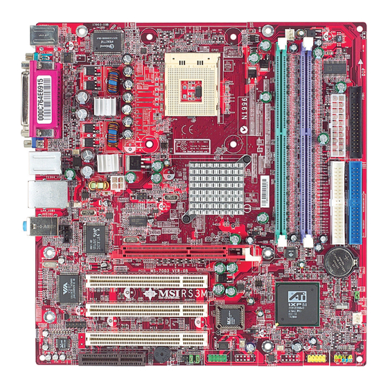
Page 12: Mainboard Layout
8100C AGP Slot JCD1 or 8100S BATT PCI Slot 1 VT6307 JBAT1 or VT6306 PCI Slot 2 IXP150 SYS_FAN1 BIOS SBRACKET PCI Slot 3 Codec J1394_A (reserved for J1394_B JFP1 JAUDIO1 VT6306) JUSB1 (optional) RS3M Series (MS-7003) v1.X M-ATX Mainboard... -
Page 13: Msi Special Features
Live Monitor™ The Live Monitor™ is a tool used to schedule the search for the latest BIOS/drivers version on the MSI Web site. To use the function, you need to install the “MSI Live Update 3” application. After installation, the “MSI Live Monitor” icon (as shown on the right) will appear on the screen. -
Page 14: Live Bios™ /Live Driver
“MSI Live Update 3” icon (as shown on the right) will appear on the screen. Double click the “MSI Live Update 3” icon, and the following screen will appear: Six buttons are placed on the left column of the screen. Click the desired button to start the update process. -
Page 15: Corecenter
MS-7003 M-ATX Mainboard CoreCenter (TM) CoreCenter - contains OC Menu panel, wherein users can determine their processor and memory type to optimize its memory capacity. This all-in- one hardware console is advanced combination of the popular PC Alert and Fuzzy Logic. Including powerful function with hardware monitor, system alert... - Page 16 Hardware Setup Left-wing: Current system status In the left sub-menu, you can configure the settings of FSB, Vcore, Memory Voltage and AGP Voltage by clicking the radio button in front of each item and make it available (the radio button will be lighted as yellow when selected), use the “+”...
-
Page 17: Chapter 2. Hardware Setup
Hardware Setup Chapter 2. Hardware Setup Hardware Setup This chapter tells you how to install the CPU, memory modules, and expansion cards, as well as how to setup the jumpers on the mainboard. It also provides the instructions on connecting the peripheral devices, such as the mouse, keyboard, etc. -
Page 18: Quick Components Guide
MS-7003 M-ATX Mainboard Quick Components Guide JPW1, p.2-9 CPU, p.2-3 JKBV1, p.2-23 DDR DIMMs, p.2-7 CPU_FAN1, p.2-15 ATX1, p.2-9 Back Panel FDD1, p.2-15 I/O, p.2-10 JTV1, p.2-20 IDE1, IDE2, JCD1, p.2-15 p.2-16 JBAT1, p.2-22 SYS_FAN1, p.2-15 SBRACKET, p.2-19 JFP1, p.2-17 JAUDIO1, p.2-18... -
Page 19: Central Processing Unit: Cpu
CPU core speed Host Clock x Core/Bus ratio 100MHz x 17 1.7 GHz MSI Reminds You... Overheating Overheating will seriously damage the CPU and system, always make sure the cooling fan can work properly to protect the CPU from overheating. -
Page 20: Cpu Installation Procedures For Socket 478
MS-7003 M-ATX Mainboard CPU Installation Procedures for Socket 478 1. Please turn off the power and unplug the power cord before Open Lever installing the CPU. 2. Pull the lever sideways away Sliding 90 degree Plate from the socket. Make sure to raise the lever up to a 90- degree angle. -
Page 21: Installing The Cpu Fan
Hardware Setup Installing the CPU Fan As processor technology pushes to faster speeds and higher performance, thermal management becomes increasingly important. To dissi- pate heat, you need to attach the CPU cooling fan and heatsink on top of the CPU. Follow the instructions below to install the Heatsink/Fan: 1. - Page 22 MS-7003 M-ATX Mainboard 5. Connect the fan power cable from the mounted fan to the 3-pin fan power connec- tor on the board. fan power cable NOTES...
-
Page 23: Memory
Hardware Setup Memory The mainboard provides two 184-pin unbuffered DDR200/DDR266/ DDR333/DDR400 SDRAM, and supports the memory size up to 2GB. To oper- ate properly, at least one DIMM module must be installed. Please refer to Appendix B for Recommended Memory Modules. DDR DIMM Slots (DDR 1~2) Memory Speed/CPU FSB Support Matrix... -
Page 24: Ddr Module Combination
MS-7003 M-ATX Mainboard DDR Module Combination Install at least one DIMM module on the slots. Memory modules can be installed on the slots in any order. You can install either single- or double- sided modules to meet your own needs. -
Page 25: Power Supply
Hardware Setup Power Supply The mainboard supports ATX power supply for the power system. Before inserting the power supply connector, always make sure that all components are installed properly to ensure that no damage will be caused. ATX 20-Pin Power Connector: ATX1 This connector allows you to connect to an ATX power supply. -
Page 26: Back Panel
MS-7003 M-ATX Mainboard Back Panel The back panel provides the following connectors: Mouse Parallel IEEE1394 L-in L-out COMA Keyboard Mouse Connector ® The mainboard provides a standard PS/2 mouse mini DIN connector for ® ® attaching a PS/2 mouse. You can plug a PS/2 mouse directly into this connector. -
Page 27: Keyboard Connector
Hardware Setup Keyboard Connector ® The mainboard provides a standard PS/2 keyboard mini DIN connector ® ® for attaching a PS/2 keyboard. You can plug a PS/2 keyboard directly into this connector. Pin Definition SIGNAL DESCRIPTION Keyboard DATA Keyboard DATA No connection Ground Keyboard Clock... -
Page 28: Serial Port Connector: Coma
MS-7003 M-ATX Mainboard Serial Port Connectors: COMA The mainboard offers one 9-pin male DIN connector as serial port COM A. This port is 16550A high speed communication ports that send/receive 16 bytes FIFOs. You can attach a serial mouse or other serial device directly to it. -
Page 29: Appendix A: Using 2-, 4- Or 6-Channel Audio Function
Line In 1/8” Stereo Audio Connectors Line Out Mic In MSI Reminds You... For advanced audio application, Realtek ALC 655 is provided to offer support for 6-channel audio operation and can turn rear audio connectors from 2-channel to 4-/6-channel audio. -
Page 30: Ieee1394 Port Connector
MS-7003 M-ATX Mainboard IEEE1394 Port Connector The mainboard provides an IEEE1394 port for users to connect to any IEEE1394 device. Parallel Port Connector: LPT1 The mainboard provides a 25-pin female centronic connector as LPT. A parallel port is a standard printer port that supports Enhanced Parallel Port (EPP) and Extended Capabilities Parallel Port (ECP) mode. -
Page 31: Connectors
Hardware Setup Connectors The mainboard provides connectors to connect to FDD, IDE HDD, case, LAN, USB Ports, IR module and CPU/System/Power Supply FAN. Floppy Disk Drive Connector: FDD1 The mainboard provides a standard floppy disk drive connector that supports 360K, 720K, 1.2M, 1.44M and 2.88M floppy disk types. CD-In Connector: JCD1 The connector is for CD-ROM audio connector. -
Page 32: Hard Disk Connectors: Ide1 & Ide2
MS-7003 M-ATX Mainboard Hard Disk Connectors: IDE1 & IDE2 The mainboard has a 32-bit Enhanced PCI IDE and Ultra DMA 33/66/10 controller that provides PIO mode 0~4, Bus Master, and Ultra DMA 33/66/100 function. You can connect up to four hard disk drives, CD-ROM, 120MB Floppy and other devices. -
Page 33: Front Panel Connector: Jfp1
Hardware Setup Front Panel Connector: JFP1 The mainboard provides one front panel connector for electrical ® connection to the front panel switches and LEDs. JFP1 is compliant with Intel Front Panel I/O Connectivity Design Guide. Front USB Connector: JUSB1 The mainboard provides one USB 2.0 pin header JUSB1 that is compliant ®... -
Page 34: Front Panel Audio Connector: Jaudio1
MS-7003 M-ATX Mainboard Front Panel Audio Connector: JAUDIO1 The JAUDIO1 front panel audio connector allows you to connect to the ® front panel audio and is compliant with Intel Front Panel I/O Connectivity Design Guide. JAUDIO1 JAUDIO1 Pin Definition SIGNAL... -
Page 35: Hardware Setup
Hardware Setup S-Bracket (SPDIF) Connector: SBRACKET The connector allows you to connect a S-Bracket for Sony & Philips Digital Interface (SPDIF). The S-Bracket offers 2 SPDIF jacks for digital audio transmission (one for optical fiber connection and the other for coaxial), and 2 analog Line-Out jacks for 4-channel audio output. -
Page 36: Tv-Out Connector: Jtv1
MS-7003 M-ATX Mainboard TV-Out Connector: JTV1 The mainboard optionally provides a TV-Out connector for you to at- tach a TV-Out bracket. The TV-Out bracket offers two types of TV-Out connectors: S-Video and RCA Composite connector. Select the appropriate one to connect to the television and the television will be able to display PC’s information. - Page 37 Hardware Setup IEEE 1394 Connectors: J1394_A (reserved) & J1394_B The mainboard is normally integrated with VIA VT6307 PCI Controller to provide one IEEE1394 pin header, J1394_B. If VIA VT6306 PCI Controller is integrated, the mainboard will provide two IEEE1394 pin headers that allow you to connect IEEE 1394 ports. J1394_A J1394_B (reserved)
-
Page 38: Jumpers
MS-7003 M-ATX Mainboard Jumpers The motherboard provides the following jumpers for you to set the computer’s function. This section will explain how to change your motherboard’s function through the use of jumpers. Clear CMOS Jumper: JBAT1 There is a CMOS RAM on board that has a power supply from external battery to keep the data of system configuration. -
Page 39: Keyboard Wake-Up Jumper: Jkbv1
VCC 5V (Default) 5V Standby Disable Keyboard Power On Function Enable Keyboard Power On function MSI Reminds You... To enable this function, you need a power supply that provides enough power for this feature. (Power Supply with 750mA 5V Standby) -
Page 40: Slots
MS-7003 M-ATX Mainboard Slots The motherboard provides one AGP slot, three 32-bit PCI bus slots and one CNR slot. AGP Slot PCI Slots CNR Slot AGP (Accelerated Graphics Port) Slot The AGP slot allows you to insert the AGP graphics card. AGP is an interface specification designed for the throughput demands of 3D graphics. -
Page 41: Pci Interrupt Request Routing
Hardware Setup PCI Interrupt Request Routing The IRQ, abbreviation of interrupt request line and pronounced I-R-Q, are hardware lines over which devices can send interrupt signals to the microprocessor. The PCI IRQ pins are typically connected to the PCI bus INT A# ~ INT D# pins as follows: Order 1 Order 2... -
Page 42: Chapter 3. Bios Setup
BIOS Setup Chapter 3. BIOS Setup BIOS Setup This chapter provides information on the BIOS Setup program and allows you to configure the system for optimum use. You may need to run the Setup program when: ² An error message appears on the screen during the system booting up, and requests you to run SETUP. -
Page 43: Entering Setup
MS-7003 M-ATX Mainboard Entering Setup Power on the computer and the system will start POST (Power On Self Test) process. When the message below appears on the screen, press <DEL> key to enter Setup. Press DEL to enter SETUP If the message disappears before you respond and you still wish to enter Setup, restart the system by turning it OFF and On or pressing the RESET button. -
Page 44: Getting Help
Press <Esc> to exit the Help screen. MSI Reminds You... The items under each BIOS category described in this chapter are under continuous update for better system performance. -
Page 45: The Main Menu
MS-7003 M-ATX Mainboard The Main Menu ® Once you enter Phoenix-Award BIOS CMOS Setup Utility, the Main Menu (Figure 1) will appear on the screen. The Main Menu allows you to select from twelve setup functions and two exit choices. Use arrow keys to select among the items and press <Enter>... - Page 46 BIOS Setup PC Health Status This entry shows your PC health status. Frequency/Voltage Control Use this menu to specify your settings for frequency/voltage control. Load High Performance Defaults Use this menu to load the BIOS values for the best system performance, but the system stability may be affected.
-
Page 47: Standard Cmos Features
MS-7003 M-ATX Mainboard Standard CMOS Features The items in Standard CMOS Features Menu are divided into 11 categories. Each category includes no, one or more than one setup items. Use the arrow keys to highlight the item and then use the <PgUp> or <PgDn> keys to select the value you want in each item. - Page 48 BIOS Setup If your hard disk drive type is not matched or listed, you can use Manual to define your own drive type manually. If you select Manual, related information is asked to be entered to the following items. Enter the information directly from the keyboard. This information should be provided in the documentation from your hard disk vendor or the system manufacturer.
-
Page 49: Advanced Bios Features
MS-7003 M-ATX Mainboard Advanced BIOS Features Hard Disk Boot Priority This feature allows you to specify the hard disk boot priority. Virus Warning The item is to set the Virus Warning feature for IDE Hard Disk boot sector protection. If the function is enabled and any attempt to write data into this area is made, BIOS will display a warning message on screen and beep. - Page 50 Setting to Enabled will increase the system performance. Settings: Enabled, Disabled. Please disable this item if your operating system doesn’t support HT Function, or unreliability and instability may occur. MSI Reminds You... Enabling the functionality of Hyper-Threading Technology for your computer system requires ALL of the following platform Components: ®...
- Page 51 MS-7003 M-ATX Mainboard Gate A20 Option This item is to set the Gate A20 status. A20 refers to the first 64KB of extended memory. When the default value Fast is selected, the Gate A20 is controlled by Port92 or chipset specific method resulting in faster system performance. When Normal is selected, A20 is controlled by a keyboard controller or chipset hardware.
- Page 52 BIOS Setup tunity to move data from a hard disk that is going to fail to a safe place before the hard disk becomes offline. Settings: Enabled and Disabled. Typematic Rate Setting This item is used to enable or disable the typematic rate setting including Typematic Rate &...
-
Page 53: Advanced Chipset Features
MS-7003 M-ATX Mainboard Advanced Chipset Features MSI Reminds You... Change these settings only if you are familiar with the chipset. Current DRAM Clock It shows the clock frequency of the installed DRAMs. (read only) DRAM Clock By This item is used to configure the clock frequency of the installed DRAM. - Page 54 BIOS Setup Current TRP This item allows you to control the number of SDRAM clocks used for the SDRAM parameters Trp. Trp specifies the minimum clock cycles required for the precharge command to be transferred to the active command. Settings: (read only).
- Page 55 MS-7003 M-ATX Mainboard AGP Aperture Size This setting controls just how much system RAM can be allocated to AGP for video purposes. The aperture is a portion of the PCI memory address range dedicated to graphics memory address space. Host cycles that hit the aperture range are forwarded to the AGP without any translation.
-
Page 56: Integrated Peripherals
BIOS Setup Integrated Peripherals OnBoard IDE Device Press <Enter> to enter the sub-menu and the following screen appears: IDE DMA Transfer Access This item is used to enable or disable the DMA transfer function of the IDE Hard Drive. The settings are: Enabled, Disabled. OnChip IDE Channel 0/1 The integrated peripheral controller contains an IDE interface with support 3-15... - Page 57 MS-7003 M-ATX Mainboard for two IDE channels. Choose [Enabled] to activate each channel separately. Settings: Enabled, Disabled. IDE Prefetch Mode The onboard IDE drive interfaces support IDE prefetching, for faster drive accesses. When you install a primary and/or secondary add-in IDE interface, set this option to Disabled if the interface does not support prefetching.
- Page 58 BIOS Setup Onboard AC97 Audio Auto allows the mainboard to detect whether an audio device is used. If an audio device is detected, the onboard AC’97 (Audio Codec’97) con- troller will be enabled; if not, it is disabled. Disable the controller if you want to use other controller cards to connect an audio device.
- Page 59 MS-7003 M-ATX Mainboard Onboard LAN Device This item allows you to enable/disable the LAN controller. Setting options: Enabled and Disabled. Onboard 1394 Device This item allows you to enable/disable the onboard IEEE1394 controller. Setting options: Enabled and Disabled. Onboard Super IO Device Press <Enter>...
- Page 60 BIOS Setup Parallel Port Mode SPP : Standard Parallel Port EPP : Enhanced Parallel Port ECP : Extended Capability Port ECP + EPP: Extended Capability Port + Enhanced Parallel Port Normal SPP/EPP/ECP/ECP+EPP To operate the onboard parallel port as Standard Parallel Port only, choose “SPP.”...
-
Page 61: Power Management Setup
MS-7003 M-ATX Mainboard Power Management Setup MSI Reminds You... S3-related functions described in this section are available only when your BIOS supports S3 sleep mode. Sleep State This item specifies the power saving modes for ACPI function. If your operat-... - Page 62 BIOS Setup Power Management Option This item is used to select the degree (or type) of power saving and is related to these modes: Suspend Mode and HDD Power Down. There are three op- tions for power management: Min Saving Minimum Power Management.
- Page 63 MS-7003 M-ATX Mainboard Soft-Off by PWRBTN This feature allows users to configure the power button function. Settings are: Instant-Off The power button functions as a normal power-on/- off button. By HardWare When you press the power button, the computer enters the suspend/sleep mode, but if the button is pressed for more than four seconds, the computer is turned off.
- Page 64 Resume Time (hh:mm:ss) You can choose what hour, minute and second the system will boot up. MSI Reminds You... If you have changed this setting, you must let the system boot up until it enters the operating system, before this function will work.
-
Page 65: Pnp/Pci Configurations
MS-7003 M-ATX Mainboard PNP/PCI Configurations This section describes configuring the PCI bus system and PnP (Plug & Play) feature. PCI, or Peripheral Component Interconnect, is a system which al- lows I/O devices to operate at speeds nearing the speed the CPU itself uses when communicating with its special components. - Page 66 BIOS Setup Press <Enter> and you will enter the sub-menu of the items. IRQ Resources list IRQ 3/4/5/7/9/10/11/12/14/15 for users to set each IRQ a type depending on the type of device using the IRQ. Settings are: PCI Device For Plug & Play compatible devices designed for PCI bus architecture.
-
Page 67: Pc Health Status
MS-7003 M-ATX Mainboard PC Health Status This section shows the status of your CPU, fan, overall system status, etc. Monitor function is available only if there is hardware monitoring mechanism onboard. CPU Warning Temperature This item is used to specify a thermal limit for CPU. If CPU temperature reaches the specified limit, the system will issue a warning which allows you to prevent the CPU overheat problem. -
Page 68: Frequency/Voltage Control
BIOS Setup Frequency/Voltage Control Use this menu to specify your settings for frequency/voltage control. Current CPU FSB Clock This shows the current front side bus clock frequency of the processor. PCI Clock Auto Detect This feature enables the BIOS to auto detect PCI device and set PCI slot clock. Options are: Enabled, Disabled. - Page 69 MS-7003 M-ATX Mainboard spikes of the pulses are reduced to flatter curves. If you do not have any EMI problem, leave the setting at Disabled for optimal system stability and performance. But if you are plagued by EMI, select Enabled for EMI reduction.
-
Page 70: Load High Performance/Bios Setup Defaults
When you select Load High Performance Defaults, a message as below appears: Pressing Y loads the default factory settings for optimal system performance. MSI Reminds You... The option is for power or overclocking users only. Use of high performance defaults will tighten most timings to increase the system performance. -
Page 71: Set Supervisor/User Password
MS-7003 M-ATX Mainboard Set Supervisor/User Password When you select this function, a message as below will appear on the screen: Type the password, up to eight characters in length, and press <Enter>. The password typed now will replace any previously set password from CMOS memory. -
Page 72: Appendix A: Using 2-, 4- Or 6-Channel Audio Function
Using Audio Function Appendix A: Using 2-, 4- & 6-Channel Audio Function The mainboard is equipped with Realtek ALC655 chip, which provides support for 6-channel audio output, including 2 Front, 2 Rear, 1 Center and 1 Subwoofer channel. ALC655 allows the board to attach 4 or 6 speakers for better surround sound effect. -
Page 73: Installing The Audio Driver
MS-7003 M-ATX Mainboard Installing the Audio Driver You need to install the driver for Realtek ALC655 chip to function properly before you can get access to 2-/4-/6-channel audio operations. Follow the procedures described below to install the drivers for different operating systems. - Page 74 Using Audio Function 3. Click Next to install the AC’97 Audio software. Clic k he r e 4. Click Finish to restart the system. Se le ct this option Clic k he r e...
-
Page 75: Software Configuration
MS-7003 M-ATX Mainboard Software Configuration After installing the audio driver, you are able to use the 2-/4-/6-channel audio feature now. Click the audio icon from the window tray at the lower- right corner of the screen to activate the AC97 Audio Configuration. - Page 76 Using Audio Function Here it provides the Karaoke function which will automatically remove human voice (lyrics) and leave melody for you to sing the song. Note that this function applies only for 2-channel audio operation. Just check the Voice Cancellation box and then click OK to activate the Karaoke function.
- Page 77 MS-7003 M-ATX Mainboard Equalizer Here you regulate each equalizer for current playing digital sound sources. You may choose the provided sound effects, and the equalizer will adjust automatically. If you like, you may also load an equalizer setting or make an new equalizer setting to save as an new one by using the buttons Load and Save.
-
Page 78: Speaker Configuration
Using Audio Function Speaker Configuration In this tab, you can easily configure your multi-channel audio function and speakers. 1. Select a desired multi-channel operation from Number of Speakers. a. Headphone for the common headphone b. 2-Channel Mode for Stereo-Speaker Output c. -
Page 79: Speaker Test
MS-7003 M-ATX Mainboard Speaker Test You can use this tab to test each connected speaker to ensure if 4- or 6- channel audio operation works properly. If any speaker fails to make sound, then check whether the cable is inserted firmly to the connector or replace the bad speakers with good ones. - Page 80 Using Audio Function S/PDIF-Out In this tab you may slelect the format of SPDIF out. MSI Reminds You... 1. 6 speakers appear on the “Speaker Test” tab only when you select “6-Channel Mode” in the “Number of Speakers” col- umn in “Speaker Configuration” tab. If you select “4-Chan- nel Mode”, only 4 speakers appear on the window.
-
Page 81: Hrtf Demo
MS-7003 M-ATX Mainboard HRTF Demo In this tab you may adjust your HRTF (Head Related Transfer Functions) 3D positional audio before playing 3D audio applications like gaming. You may also select different environment to choose the most suitable environment you like. - Page 82 Using Audio Function General In this tab it provides some information about the AC97 Audio Configu- ration utility, including Audio Driver Version, DirectX Version, Audio Control- ler & AC97 Codec. You may also select the language of this utility by choosing from the Language list.
- Page 83 MS-7003 M-ATX Mainboard Using 2-, 4- & 6- Channel Audio Function After installing the audio driver, you are able to use the 4-/6-channel audio feature now. To enable 4- or 6-channel audio operation, first connect 4 or 6 speakers to the appropriate audio connectors, and then select 4- or 6-channel audio setting in the software utility.
- Page 84 Using Audio Function Connecting the Speakers When you have set the Multi-Channel Audio Function mode properly in the software utility, connect your speakers to the correct phone jacks in accordance with the setting in software configuration. n 2-Channel Mode for Stereo-Speaker Output When this mode is selected, it is recommended to attach the speakers to the Line Out connector on the back panel instead of the Line Out connector on the S-Bracket.
- Page 85 MS-7003 M-ATX Mainboard n 4-Channel Mode for 4-Speaker Output When this mode is selected, plug the two front speakers to the Line Out connector on the back panel, and the other two rear speakers to the Line Out connector on the S-Bracket.
- Page 86 Line Out (Rear channels) Back Panel S-Bracket MSI Reminds You... If the Center and Subwoofer speaker exchange their audio channels when you play video or music on the computer, a converter may be required to exchange center and subwoofer audio signals.
- Page 87 MS-7003 M-ATX Mainboard n Digital Audio Output When any Multi-Channel Audio Function mode is selected, you may also connect your speakers to the Optical or Coaxial SPDIF phone jack on the S-Bracket to exprience digital surround sound effect. Remove the plug from the optical SPIDF phone jack before inserting the fiber-optic cable, and read the following diagram and captions for the function of each phone jack on the S-Bracket.
-
Page 88: Using The Back Panel Only
Using Audio Function Using the Back Panel only In addition to a default 2-channel analog audio output function, the audio connectors on the Back Panel also provide 4- or 6-channel analog audio output function if a proper setting is made in the software utility. Read the following steps to have the Multi-Channel Audio Function properly set in the software utility, and have your speakers correctly connected to the Back Panel. - Page 89 MS-7003 M-ATX Mainboard n 4-Channel Mode for 4-Speaker Output The audio jacks on the back panel always provide 2-channel analog audio output function, however these audio jacks can be transformed to 4- or 6- channel analog audio jacks by selecting the corresponding multi-channel operation from No.
- Page 90 * Both Line In and MIC function are converted to Line Out function when 6-Channel Mode for 6-Speaker Output is selected. MSI Reminds You... If the Center and Subwoofer speaker exchange their audio channels when you play video or music on the computer, a converter may be required to exchange center and subwoofer audio signals.
-
Page 91: Appendix B: Recommended Memory Modules
Memory Modules Appendix B: Recommended Memory Modules PC2100 DDR RAM (DDR266) System Configuration Manufacturer Model No. Spec. Processor Intel 2.0G 400MHz Memory As Follows VGA Card On Board Lan Card On Board Sound Card On Board Hard Drive Maxtor Diamond Max Plus & 6E030L0-1A UDMA 133 30GB CD-ROM MS8216... - Page 92 MS-7003 M-ATX Mainboard Model Size Memory Slot Memory Bandwidth R.S.T Benchmark Micron MT46V16M8TG-75B 256MB Nanya NT5DS32M8BT-75B 256MB Toshiba TC59WM807BFT-70 256MB Micron MT46V16M8TG-75B 256MB Nanya NT5DS32M8BT-75B 256MB Toshiba TC59WM807BFT-70 256MB Micron MT46V16M8TG-75B 256MB Nanya NT5DS32M8BT-75B 256MB SEC K4H280838D-TCB0 256MB Micron MT46V16M8TG-75B...
-
Page 93: Memory Modules
Memory Modules PC2100 DDR RAM (DDR266) System Configuration Manufacturer Model No. Spec. Processor Intel 2.4G (533)MHz Memory As Follows VGA Card On Board Lan Card On Board Sound Card On Board Hard Drive Maxtor Diamond Max Plus & 6E030L0-1A UDMA 133 30GB CD-ROM MS8216 16X DVD-ROM... - Page 94 MS-7003 M-ATX Mainboard Model Size Memory Slot Memory Bandwidth R.S.T Benchmark Micron MT46V16M8TG-75B 256MB Nanya NT5DS32M8BT-75B 256MB Toshiba TC59WM807BFT-70 256MB Micron MT46V16M8TG-75B 256MB Nanya NT5DS32M8BT-75B 256MB Toshiba TC59WM807BFT-70 256MB Micron MT46V16M8TG-75B 256MB Nanya NT5DS32M8BT-75B 256MB SEC K4H280838D-TCB0 256MB Micron MT46V16M8TG-75B...
- Page 95 Memory Modules PC2700 DDR RAM (DDR333) System Configuration Manufacturer Model No. Spec. Processor Intel 2.4G (533)MHz Memory As Follows VGA Card On Board Lan Card On Board Sound Card On Board Hard Drive Maxtor Diamond Max Plus & 6E030L0-1A UDMA 133 30GB CD-ROM MS8216 16X DVD-ROM...
- Page 96 MS-7003 M-ATX Mainboard Model Size Memory Slot Memory Bandwidth R.S.T Benchmark ü ü Hynix HYMD116645B8J-J 128MB ü (Hynix HY5DU28822BT-J) ü ü Infineon HYS64D16301GU-6-B 128MB ü (Infineon HYB25D256160BT-6B) ü ü Micron MT4VDDT1664AG-335C3 SG 128MB ü (Micron MT46V16M16TG-6T C) ü ü Nanya...
- Page 97 Memory Modules Model Size Memory Slot Memory Bandwidth R.S.T Benchmark ü ü Nanya NT256D64S88B1G-6K 256MB ü (Nanya NT5DS32M8BT-6K) ü ü Nanya NT256D64S8HA1G-6K 256MB ü (Nanya NT5DS16M8AT-6K) ü ü M368L3223DTM-CB3 256MB ü (SEC K4H560838D-TCB3) ü ü M368L3223ETN-CB3 256MB ü (SEC K4H560838E-TCB3) ü...
- Page 98 MS-7003 M-ATX Mainboard PC2700 DDR RAM (DDR333) System Configuration Manufacturer Model No. Spec. Processor Intel 2.8G (800)MHz Memory As Follows VGA Card On Board Lan Card On Board Sound Card On Board Hard Drive Maxtor Diamond Max Plus & 6E030L0-1A...
- Page 99 Memory Modules Model Size Memory Slot Memory Bandwidth R.S.T Benchmark ü ü Hynix HYMD116645B8J-J 128MB ü (Hynix HY5DU28822BT-J) ü ü Infineon HYS64D16301GU-6-B 128MB ü (Infineon HYB25D256160BT-6B) ü ü Micron MT4VDDT1664AG-335C3 SG 128MB ü (Micron MT46V16M16TG-6T C) ü ü Nanya NT128D64SH4B1G-6K 128MB ü...
- Page 100 MS-7003 M-ATX Mainboard PC3200 DDR RAM (DDR400) System Configuration Manufacturer Model No. Spec. Processor Intel 2.8G (800)MHz Memory As Follows VGA Card On Board Lan Card On Board Sound Card On Board Hard Drive Maxtor Diamond Max Plus & 6E030L0-1A...
- Page 101 Memory Modules Model Size Memory Slot Memory Bandwidth R.S.T Benchmark ü ü Infineon HYS64D16301GU-5-B 128MB ü (Infineon HYB25D256160BT-5) ü ü Nanya NT128D64SH4B1G-5 128MB ü (Nanya NT5DS16M16BT-5) ü ü A-DATA MD0M05F3G31JB1EAZ 256MB ü (Mosel V58C2256804SAT5) ü ü Apacer 77.10636.115 256MB ü (Infineon HYB25D256800BT-5B) ü...
- Page 102 MS-7003 M-ATX Mainboard Model Size Memory Slot Memory Bandwidth R.S.T Benchmark ü ü Infineon HYS64D32300GU-5-B 256MB ü (Infineon HYB25D256800BT-5) ü ü Infineon HYS64D32300HU-5-C 256MB ü (Infineon HYB25D256800CE-5C) ü ü Kingston KVR400X64C25/256 256MB ü (Winbond W942508BH-5) LEGEND L3264D37-643HDC9B 256MB (Hynix HY5DU56822BT-D43) ü...
- Page 103 Memory Modules Model Size Memory Slot Memory Bandwidth R.S.T Benchmark ü Kingston KVR400X64C25/512 512MB ü (Winbond W942508BH-5) ü ü Micron MT16VDDT6464AG-40BC4 512MB ü (Micron MT46V32M8TG-5B C) ü (Nanya NT5DS32M8BT-5T) ü AL6D8A53TK1-5B 512MB ü (PSC A2S56D30ATP-5) ü ü AL6D8B53T-5B1K 512MB ü (PSC A2S56D30BTP -5) ü...
Need help?
Do you have a question about the MS-7003 and is the answer not in the manual?
Questions and answers