Table of Contents
Advertisement
Advertisement
Table of Contents

Related Manuals for MSI KT880 Delta


Summary of Contents for MSI KT880 Delta
- Page 1 KT880 Delta MS-7047 (v1.X) ATX Mainboard G52-M7047X1...
-
Page 2: Fcc-B Radio Frequency Interference Statement
Manual Rev: 1.0 Release Date: March 2004 FCC-B Radio Frequency Interference Statement This equipment has been tested and found to comply with the limits for a class B digital device, pursuant to part 15 of the FCC rules. These limits are designed to provide reasonable protection against harmful interference when the equipment is operated in a commercial environment. -
Page 3: Copyright Notice
Copyright Notice The material in this document is the intellectual property of MICRO-STAR INTERNATIONAL. We take every care in the preparation of this document, but no guarantee is given as to the correctness of its contents. Our products are under continual improvement and we reserve the right to make changes without notice. -
Page 4: Safety Instructions
Alternatively, please try the following help resources for further guidance. Visit the MSI homepage & FAQ site for technical guide, BIOS updates, driver updates, and other information: http://www.msi.com.tw & http://www.msi. -
Page 5: Table Of Contents
Safety Instructions ...................... iv Technical Support ......................iv Chapter 1. Getting Started ................... 1-1 Mainboard Specifications ................... 1-2 Mainboard Layout ....................1-4 MSI Special Features ..................1-5 Color Management ..................1-5 Round Cable (Optional) ................. 1-6 Core Cell Chip ..................... 1-7 Dynamic Overclocking Technology .............. - Page 6 Fan Power Connectors: CFAN1 / SFAN1 / NBFAN1 ......... 2-13 ATA133 Hard Disk Connectors: IDE1 & IDE2 ..........2-14 Serial ATA/Serial ATA RAID Connectors controlled by VIA VT8237: SATA1, SATA2 (Optional) ..............2-15 Chassis Intrusion Switch Connector: J1 ........... 2-16 Front Panel Connectors: JFP1 &...
- Page 7 Software Access Point ..................4-6 Terminology ....................4-6 Access Point Mode ..................4-7 WLAN Card Mode ..................4-8 Live Update ......................4-9 MEGA STICK ...................... 4-10 Basic Function ..................... 4-10 Non-Unicode programs supported ............. 4-12 Core Center (for AMD K8 Processor) .............. 4-14 Audio Speaker Setting ..................
-
Page 8: Chapter 1. Getting Started
Getting Started Chapter 1. Getting Started Getting Started Thank you for choosing the KT880 Delta (MS-7047 v1.X) ATX ® mainboard. The KT880 Delta is based on VIA KT880 & VT8237 chipsets ® for optimal system efficiency. Designed to fit the advanced AMD... -
Page 9: Mainboard Specifications
Supports Socket A (Socket-462) for AMD ® Athlon™ XP /Duron™ processors. FSB @ 400 MHz. Supports up to 3200+ or higher speed. (For the latest information about CPU, please visit http://www.msi.com.tw/program/ products/mainboard/mbd/pro_mbd_cpu_support.php) Chipset ® KT880 chipset - Supports FSB 400/333/266 MHz. - Page 10 Getting Started On-Board Peripherals On-Board Peripherals include: - 1 floppy port supports 2 FDDs with 360K, 720K, 1.2M, 1.44M and 2.88Mbytes - 1 serial ports (COM A) - 1 parallel port supports SPP/EPP/ECP mode - 8 USB 2.0 ports (Rear x 4 / Front x 4) - 1 RJ45 LAN jack - 1 D-Bracket2 pinheader - 1 Line-In / Line-Out /Mic...
-
Page 11: Mainboard Layout
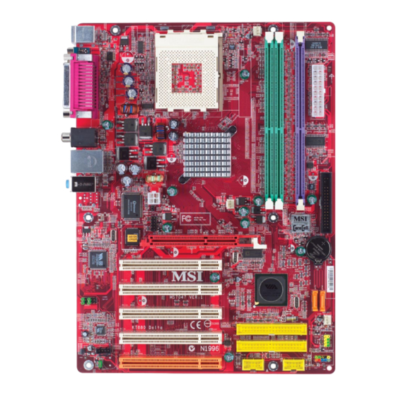
BATT PCI Slot 1 VT6122/VT6103L (Optional) PCI Slot 2 SATA1 SATA2 VT8237 PCI Slot 3 JAUD1 SFAN1 IDE 1 PCI Slot 4 VT1617A IDE 2 JFP2 JCD1 PCI Slot 5 JUSB1 JUSB2 JBAT1 JFP1 KT880 Delta (MS-7047) v1.X ATX Mainboard... -
Page 12: Msi Special Features
Getting Started MSI Special Features Color Management MSI has a unified color management rule for some connectors on the mainboards, which helps you to install the memory modules, expansion cards and other peripherals devices more easily and conveniently. Standard IDE ATA66/100/133 connector: yellow... -
Page 13: Round Cable (Optional)
MS-7047 ATX Mainboard Round Cable (Optional) Round cable is an enhanced cable for PCI IDE and Ultra DMA controller. It has the following benefits: Data transfer rate started by 133MB/s Backward compatibility (ATA33/66/100/133) Higher performance than traditional Flat cable (data rate) Improved data robustness Better airflow due to thinner ATA/133 cable Connect to the system... -
Page 14: Core Cell Tm Chip
Getting Started Core Cell Chip By diagnosing the current system utilization, the CoreCell™ Chip automatically tunes your motherboard to the optimal state, leading to less noise, longer duration, more power-saving and higher performance. Features of CoreCell™ Speedster -- Advanced O.C. design. -- Superior O.C. -
Page 15: Dynamic Overclocking Technology
D.O.T D.O.T Dynamic Overclocking Technology MSI Reminds You... Even though the Dynamic Overclocking Technology is more stable than manual overclocking, basically, it is still risky. We suggest user to make sure that your CPU can afford to overclocking regularly first. -
Page 16: Chapter 2. Hardware Setup
Hardware Setup Chapter 2. Hardware Setup Hardware Setup This chapter tells you how to install the CPU, memory modules, and expansion cards, as well as how to setup the jumpers on the mainboard. Also, it provides the instructions on connecting the peripheral devices, such as the mouse, keyboard, etc. -
Page 17: Quick Component Guide
MS-7047 ATX Mainboard Quick Components Guide CPU, p.2-3 JPW1, p.2-8 CFAN1, p.2-13 DDR DIMMs, p.2-6 J1, p.2-16 SO CKET 462 JWR1, p.2-8 Back Panel I/O, p.2-9 NBFAN1, 2-13 FDD1, p.2-13 JLED1, p.2-17 AGP Slot, p.2-20 PCI Slots, p.2-20 SATA1,SATA2, p.2-15 JAUD1, p.2-18 SFAN1, p.2-13 JFP2, p.2-16... -
Page 18: Central Processing Unit: Cpu
If you do not find the heat sink and cooling fan, contact your dealer to purchase and install them before turning on the computer. For the latest information about CPU, please visit http://www.msi.com.tw/ program/products/mainboard/mbd/pro_mbd_cpu_support.php Memory Speed/CPU FSB Support Matrix... -
Page 19: Cpu Installation Procedures For Socket 462
MS-7047 ATX Mainboard CPU Installation Procedures for Socket 462 1. Please turn off the power and unplug the power cord before installing the CPU. Open Lever Sliding 90 degree Plate 2. Pull the lever sideways away from the socket. Make sure to raise the lever up to a 90-de- gree angle. -
Page 20: Installing Amd Athlon Cpu (Socket 462) Cooler Set
MSI Reminds You... Please apply some heat sink paste on top of CPU to dissipate the... -
Page 21: Memory
Line Memory Module) modules and supports the memory size up to 3GB. You can install DDR400 / 333 / 266 modules on the DDR DIMM slots (DIMM 1~3). For the updated supporting memory modules, please visit http://www.msi. com.tw/program/products/mainboard/mbd/pro_mbd_trp_list.php. DDR DIMM Slots DIMM 1~3... -
Page 22: Installing Ddr Modules
System Density 128MB~1GB 128MB~1GB 256MB~2GB MSI Reminds You... Dual-channel DDR works ONLY in the DIMM1-DIMM3 combination listed in the table above. Installing DDR Modules 1. The DDR DIMM has only one notch on the center of module. The module will only fit in the right orientation. -
Page 23: Power Supply
5V_SB JWR1 ATX 12V Power Connector: JPW1 This 12V power connector is used to provide power to the CPU. JPW1 Pin Definition SIGNAL JPW1 MSI Reminds You... Power supply of 300 (and up) watt is highly recommended for system stability. -
Page 24: Back Panel
Hardware Setup Back Panel The back panel provides the following connectors: L-in Parallel SPDIF Out Mouse Keyboard USB Ports USB Ports L-out COMA Mouse Connector (in green) ® The mainboard provides a standard PS/2 mouse mini DIN connector for at- ®... -
Page 25: Serial Port Connector: Com A
SPDIF-out is a jack for coaxial fiber connection for digital audio transmission. Line In Line Out S/PDIF Out-Coaxial MSI Reminds You... For advanced audio application, VIA VT1617 audio chip is provided to offer support for 6-channel audio operation and can turn rear audio connectors from 2-channel to 4-/6-channel audio. 2-10... - Page 26 Hardware Setup RJ-45 LAN Jack: Giga-bit LAN (VT6122) / 10/100 LAN (VT6103L) (Optional) The mainboard provides two standard RJ-45 jacks for connection to Local Area Network (LAN). Giga-bit LAN enables data to be transferred at 1000, 100 or 10Mbps. You can connect a network cable to either LAN jack. Link Indicator Activity Indicator For 10/100 LAN Jack...
-
Page 27: Parallel Port Connector: Lpt1
MS-7047 ATX Mainboard Parallel Port Connector: LPT1 The mainboard provides a 25-pin female centronic connector as LPT. A parallel port is a standard printer port that supports Enhanced Parallel Port (EPP) and Ex- tended Capabilities Parallel Port (ECP) mode. Pin Definition SIGNAL DESCRIPTION STROBE... -
Page 28: Connectors
+12V +12V CFAN1 SFAN1 NBFAN1 MSI Reminds You... 1. Always consult the vendors for proper CPU cooling fan. ® 2. Please refer to the recommended CPU fans at AMD official website. 3. CFAN1 supports the fan control. You can install Core Center utility that will automatically control the CPU fan speed according to the actual CPU temperature. -
Page 29: Ata133 Hard Disk Connectors: Ide1 & Ide2
IDE2 (Secondary IDE Connector) IDE2 can also connect a Master and a Slave drive. MSI Reminds You... If you install two hard disks on cable, you must configure the second drive to Slave mode by setting its jumper. Refer to the hard disk documentation supplied by hard disk vendors for jumper setting instructions. -
Page 30: Serial Ata/Serial Ata Raid Connectors Controlled By Via Vt8237: Sata1, Sata2 (Optional)
Take out the dust cover and connect to the hard disk devices Connect to serial ATA ports MSI Reminds You... Please do not fold the serial ATA cable in a 90-degree angle, which will cause the loss of data during the transmission. 2-15... -
Page 31: Chassis Intrusion Switch Connector: J1
MS-7047 ATX Mainboard Chassis Intrusion Switch Connector: J1 This connector is connected to a 2-pin chassis switch. If the chassis is opened, the switch will be short. The system will record this status and show a warning message on the screen. To clear the warning, you must enter the BIOS utility and clear the record. -
Page 32: Cd-In Connector: Jcd1
Hardware Setup CD-In Connector: JCD1 The connector is for CD-ROM audio connector. GND R JCD1 D-Bracket™ 2 Connector: JLED1 The mainboard comes with a JLED1 connector for you to connect to D-Bracket™ 2. D-Bracket™ 2 is a USB Bracket that supports both USB1.1 & 2.0 spec. It integrates four LEDs and allows users to identify system problem through 16 various combina- tions of LED signals. -
Page 33: Front Usb Connectors: Jusb1 & Jusb2
Left channel audio signal to front panel AUD_RET_L Left channel audio signal return from front panel MSI Reminds You... If you don’t want to connect to the front audio header, pins 5 & 6, 9 & 10 have to be jumpered in order to have signal output directed to the rear audio ports. -
Page 34: Jumper
JBAT1 Keep Data Clear Data MSI Reminds You... You can clear CMOS by shorting 2-3 pin while the system is off. Then return to 1-2 pin position. Avoid clearing the CMOS while the system is on; it will damage the mainboard. -
Page 35: Slots
MS-7047 ATX Mainboard Slots The motherboard provides one AGP slot, and five 32-bit PCI bus slots. AGP (Accelerated Graphics Port) Slot The AGP slot allows you to insert the AGP graphics card. AGP is an interface specification designed for the throughput demands of 3D graphics. It introduces a 66MHz, 32-bit channel for the graphics controller to directly access main memory. -
Page 36: Chapter 3. Bios Setup
SETUP. You want to change the default settings for customized features. MSI Reminds You... 1. The items under each BIOS category described in this chapter are under continuous update for better system performance. -
Page 37: Entering Setup
MS-7047 ATX Mainboard Entering Setup Power on the computer and the system will start POST (Power On Self Test) process. When the message below appears on the screen, press <DEL> key to enter Setup. DEL: Setup F11: Boot Menu F12: Network boot TAB: Logo F10: Flash Recovery If the message disappears before you respond and you still wish to enter Setup,... -
Page 38: Control Keys
The preset Optimal Defaults of the BIOS setup program provide optimal performance settings for all devices and the system. MSI Reminds You... The items under each BIOS category described in this chapter are under continuous update for better system performance. Therefore, the description may be slightly different from the latest BIOS and should be held for reference only. -
Page 39: The Main Menu
MS-7047 ATX Mainboard The Main Menu Once you enter AMIBIOS NEW SETUP UTILITY, the Main Menu will appear on the screen. Use arrow keys to move among the items and press <Enter> to enter the sub-menu. Standard CMOS Features Use this menu for basic system configurations, such as time, date etc. Advanced BIOS Features Use this menu to setup the items of AMI ®... - Page 40 BIOS Setup Cell_Menu Use this menu to specify your settings for frequency/voltage control. Load Fail-Safe Defaults Use this menu to load the default values set by the BIOS vendor for stable system performance. Load Optimized Defaults Use this menu to load the default values set by the mainboard manufacturer specifi- cally for optimal performance of the mainboard.
-
Page 41: Standard Cmos Features
MS-7047 ATX Mainboard Standard CMOS Features The items in Standard CMOS Features Menu includes some basic setup items. Use the arrow keys to highlight the item and then use the <PgUp> or <PgDn> keys to select the value you want in each item. Date (MM:DD:YY) This allows you to set the system to the date that you want (usually the current date). - Page 42 BIOS Setup Device/Vendor/Size These 3 items show the information about the specified item. Read-only. LBA/Large Mode This item allows you to enable or disable the LBA (Logical Block Address, the logical block size in hard disk) mode. Setting options: [Auto], [Disabled]. DMA Mode This item allows you to enable or disable the DMA (Direct Memory Access) mode.
-
Page 43: Advanced Bios Features
MS-7047 ATX Mainboard Advanced BIOS Features Quick Boot Setting the item to [Enabled] allows the system to boot within 5 seconds since it will skip some check items. Available options: [Enabled], [Disabled]. Boot Sector Protection This function protects the BIOS from accidental corruption by unauthorized users or computer viruses. - Page 44 These items allow you to set the sequence of boot devices where AMIBIOS attempts to load the operating system. MSI Reminds You... Available settings for “1st/2nd/3rd Boot Device” vary depending on the bootable devices you have installed. For example, if you did not install a floppy drive, the setting “Floppy”...
-
Page 45: Advanced Chipset Features
MS-7047 ATX Mainboard Advanced Chipset Features MSI Reminds You... Change these settings only if you are familiar with the chipset. Configure DRAM Timing by SPD Selects whether DRAM timing is controlled by the SPD (Serial Presence Detect) EEPROM on the DRAM module. Setting to [Auto By SPD] enables DRAM timings and the following related items to be determined by BIOS based on the configurations on the SPD. - Page 46 BIOS Setup to precharge. If insufficient time is allowed for the RAS to accumulate its charge before DRAM refresh, refresh may be incomplete and DRAM may fail to retain data. This item applies only when synchronous DRAM is installed in the system. Available settings: [6T], [7T], [8T], [9T].
-
Page 47: Integrated Peripherals
MS-7047 ATX Mainboard Integrated Peripherals USB 1.1 Ports Configuration This setting is used to enable/disable the onboard USB ports. Setting options: [Disabled], [USB 2 Ports], [USB 4 Ports], [USB 6 Ports], [USB 8 Ports]. USB Device Legacy Support Set to [Enabled] if you need to use any USB 1.1/2.0 device in the operating system that does not support or have any USB 1.1/2.0 driver installed, such as DOS and SCO Unix. - Page 48 BIOS Setup IDE Devices Configuration Press <Enter> to enter the sub-menu and the following screen appears: On-Chip IDE Controller The integrated peripheral controller contains a IDE interface with support for two IDE channels. Select [Disabled] to disable the integrated IDE controller, [Primary] to enable only the primary IDE controller, [Secondary] to enable only the secondary IDE controller, or [Both] to enable both IDE controllers.
- Page 49 MS-7047 ATX Mainboard Parallel Port Mode This item selects the operation mode for the onboard parallel port: [ECP], [Normal], [Bi- Dir] or [EPP]. Parallel Port IRQ This item allows you to set parallel port IRQ. Setting options: [IRQ5], [IRQ7]. SATA Devices Configuration Press <Enter>...
-
Page 50: Power Management Features
BIOS Setup Power Management Features MSI Reminds You... S3-related functions described in this section are available only when your BIOS supports S3 sleep mode. ACPI Standby State This item specifies the power saving modes for ACPI function. If your operating... - Page 51 MS-7047 ATX Mainboard Suspend Time Out (Minute) If system activity is not detected for the length of time specified in this field, all devices except CPU will be shut off. Settings: [Disabled], [1], [2], [4], [8], [10], [20], [30], [40], [50], [60]. Power Button Function This feature allows users to configure the Power Button function.
- Page 52 Time (HH:MM:SS) 00 ~ 23 : 00 ~ 59 : 00 ~ 59 MSI Reminds You... If you have changed this setting, you must let the system boot up until it enters the operating system, before this function will work.
-
Page 53: Pnp/Pci Configuration
MS-7047 ATX Mainboard PNP/PCI Configurations This section describes configuring the PCI bus system and PnP (Plug & Play) feature. PCI, or Peripheral Component Interconnect, is a system which allows I/O devices to operate at speeds nearing the speed the CPU itself uses when communicating with its special components. - Page 54 BIOS Setup PCI Slot1 IRQ, PCI Slot2 IRQ, PCI Slot3 IRQ, PCI Slot4 IRQ These items specify the IRQ line for each PCI slot. Setting options: [3], [4], [5], [7], [9], [10], [11], [12], [14], [15], [Auto]. Selecting [Auto] allows BIOS to automatically deter- mine the IRQ line for each PCI slot.
-
Page 55: H/W Monitor
MS-7047 ATX Mainboard H/W Monitor This section shows the status of your CPU, fan, overall system status, etc. Monitor function is available only if there is hardware monitoring mechanism onboard. CPU Shutdown Temperature If the CPU temperature reaches the upper limit preset in this setting, the system will be shut down automatically. - Page 56 BIOS Setup CPU/System Temperature, CPU/System FAN Speed, Vcore, +3.3 V, +5.0 V, +12.0V, -12.0V, -5.0V These items display the current status of all of the monitored hardware devices/ components such as CPU voltages, temperatures and all fans’ speeds. 3-21...
-
Page 57: Cell Menu
Cell Menu The items in Cell Menu includes some important settings of CPU, AGP, DRAM and overclocking functions. MSI Reminds You... Change these settings only if you are familiar with the chipset. Current CPU Clock, Current DDR Memory Frequency These two items show the current clocks of CPU & DDR memory frequency. Read- only. - Page 58 5th level of overclocking, increasing the CPU frequency by 10%. [Commander] 6th level of overclocking, increasing the CPU frequency by 15%. MSI Reminds You... 1. Even though the Dynamic Overclocking Technology is more stable than manual overclocking, basically, it is still risky. We suggest user to make sure that your CPU can afford to overclocking regu- larly first.
- Page 59 Options: [Disabled], [Enabled]. MSI Reminds You... The settings shown in different color in CPU Voltage, Memory Voltage and AGP Voltage help to verify if your setting is proper for your system.
-
Page 60: Bios Setting Password
Always, the password is required both at boot and at entry to Setup. If set to Setup, password prompt only occurs when you try to enter Setup. MSI Reminds You... About Supervisor Password & User Password: Supervisor password: Can enter and change the settings of the Setup menu. -
Page 61: Load Fail-Safe/Optimized Defaults
MS-7047 ATX Mainboard Load Fail-Safe/Optimized Defaults The two options on the main menu allow users to restore all of the BIOS settings to the default Fail-Safe or Optimized values. The Optimized Defaults are the default values set by the mainboard manufacturer specifically for optimal performance of the mainboard. -
Page 62: Chapter 4. Introduction To Digicell
Chapter 2. Hardware Setup Introduction to DigiCell DigiCell, the most useful and powerful utility that MSI has spent much research and efforts to develop, helps users to monitor and configure all the integrated peripherals of the system, such as audio program, power management, MP3 files management and communication / 802.11g WLAN... -
Page 63: Main
Introduction: Click on each icon appears above to enter the sub-menu to make further configuration. Click on this button and to link to MSI website: http://www.msi.com.tw. Quick Guide Click on this button and the quick guide of DigiCell will be displayed for you to review. - Page 64 Power on Agent In this sub-menu, you can configure date, time and auto-executed programs of the power-on, power-off and restarting features. MSI Reminds You... Click on back button in every sub-menu and it will bring you back to the main menu.
-
Page 65: H/W Diagnostic
In the H/W Diagnostic sub-menu, you can see the information, status and note of each DigiCell. You can double check the connection and installation of the item marked as gray. You may also click on the Mail to MSI button to send your questions or suggestions to MSI’s technical support staff. -
Page 66: Communication
Introduction to DigiCell Communication In the Communication sub-menu, you can see the status of all the LAN / WLAN / Bluetooth on the screen if the hardware is installed. The first icon indicates the onboard LAN on your system, the second icon indicates the wireless LAN status, and the third one is the information about the bluetooth on your system. -
Page 67: Software Access Point
MS-7047 ATX Mainboard MSI Feature Software Access Point In the Software Access Point sub-menu, you can see the status of communicating on your system and choose the desired software access point mode by clicking on the desired icon, in which the default settings are configured for your usage. The default software access point mode is set to WLAN Card Mode. -
Page 68: Access Point Mode
Introduction to DigiCell Access Point Mode Click on “Setting” button of the Access Point Mode and the following screen will display. IP Sharing Click on this icon to enable/disable the IP sharing. The default of this s e t t i n g disabled. -
Page 69: Wlan Card Mode
MS-7047 ATX Mainboard MSI Feature enable this feature, only PCs with MAC address located in Association Control List can connect to the wireless LAN. MAC Address MAC stands for Media Access Control. A MAC address is the hardware address of a device connected to a network. -
Page 70: Live Update
BIOS/drivers/VGA BIOS/VGA Driver/OSD/Utility online so that you don’t need to search for the correct BIOS/driver version throughout the whole Web site. To use the function, you need to install the “MSI Live Update 3” application. After the installation, the “MSI Live Up- date 3”... -
Page 71: Mega Stick
MS-7047 ATX Mainboard MSI Feature MEGA STICK In the MEGA STICK sub-menu, you can configure the settings of MSI MEGA STICK and the media files (*.m3u, *.mp3, *.wav, *.cda, *.wma) on your system. Basic Function Here you can edit your own play list with the buttons “load”, “save”, “delete”, “shuttle”, “repeat”... - Page 72 Introduction to DigiCell There is also a toolbar for you to execute some basic function, like play, stop, pause, previous/next song, song info and volume adjusting. There is also a scroll bar on the top for you to forward/rewind. pause previous next forward/rewind...
-
Page 73: Non-Unicode Programs Supported
MS-7047 ATX Mainboard MSI Feature Non-Unicode programs supported If you are using an operating system in European languages, and you’d like to play the media files in MEGA STICK with East-Asian languages (such as Chinese, Japanese... etc.), it is possible that the file names display incorrectly. - Page 74 Introduction to DigiCell 3. Then go to the [Advanced] tab and select the language you want to be supported (the language of the filename in the MegaStick) from the drop- down list in the [Language for non-Unicode programs], then click [Apply]. The system will install the necessary components from your Microsoft Setup CD immediately.
-
Page 75: Core Center (For Amd K8 Processor)
MS-7047 ATX Mainboard MSI Feature Core Center Click on the Core Center icon in the main menu and the Core Center program will be enabled. (TM) CoreCenter - contains OC Menu panel, users can determine their processor and memory type to optimize its memory capacity. Including powerful function with hard-... - Page 76 Introduction to DigiCell Left-wing: Current system status In the left sub-menu, you can configure the settings of FSB, Vcore, Memory Voltage and AGP Voltage by clicking the radio button in front of each item and make it available (the radio button will be lighted as yellow when selected), use the “+” and “-” buttons to adjust, then click “OK”...
-
Page 77: Audio Speaker Setting
MS-7047 ATX Mainboard MSI Feature Audio Speaker Setting In the Audio Speaker Setting sub-menu, you can configure the multi-channel audio operation, perform speaker test, and choose the environment you prefer while en- joying the music. You can scroll the bar of each equalizer to regulate for current playing digital sound source. - Page 78 Introduction to DigiCell Click on the “Speaker test” button and the following dialogue box will appear: In this Speaker Configuration dialogue box, select the audio configuration which is identical to the audio jack on your mainboard. Once the correct audio configuration is selected, click “Apply”...
-
Page 79: Power On Agent
Click “OK” to restart the computer right away or click “Later” to restart your computer later. MSI Reminds You... Please note that the new setting will not take effect until you restart your computer. -
Page 80: Power Off / Restart
Delete. delete the added program MSI Reminds You... You can also enable the Every turn on function, which will enable the specified program(s) and file(s) every time the Digi Cell utility runs. -
Page 81: Auto Login
MS-7047 ATX Mainboard MSI Feature Auto Login Since the Power On function allows the system to power on automatically, you may have to enable this Auto Login function in the following situations: 1. If you are using a computer belonging to a domain in office, and you need to enter your user name &... -
Page 82: Chapter 5. Via Vt8237 Serial Ata Raid Introduction
VIA VT8237 Serial ATA RAID Introduction Chapter 5. VIA VT8237 Serial ATA RAID Introduction VIA VT8237 Serial ATA RAID Appendix. Using 4- or 6-Channel Introduction Audio Function The Southbridge VT8237 provides a hybrid solution that combines two independent SATA ports for support of up to two Serial ATA (Serial ATA RAID) drives. -
Page 83: Introduction
MS-7047 ATX Mainboard Introduction This section gives a brief introduction on the RAID-related background knowledge and a brief introduction on VIA SATA RAID Host Controller. For users wishing to install their VIA SATA RAID driver and RAID software, proceed to Driver and RAID Software Installation section. -
Page 84: Bios Configuration
VIA VT8237 Serial ATA RAID Introduction BIOS Configuration When the system powers on during the POST (Power-On Self Test) process, press <Tab> key to enter the BIOS configuration. The Serial ATA RAID volume may be configured using the VIA Tech. RAID BIOS. Always use the arrow keys to navigate the main menu, use up and down arrow key to select the each item and press <Enter>... -
Page 85: Create Disk Array
Create Disk Array Use the up and down arrow keys to select the Create Array command and press <Enter>. MSI Reminds You... The “Channel”, “Drive Name”, “Mode” and “Size (GB)” in the following example might be different from your system. - Page 86 VIA VT8237 Serial ATA RAID Introduction After array mode is selected, there are two methods to create a disk array. One method is “Auto Setup” and the other one is “Select Disk Drives”. Auto Setup allows BIOS to select the disk drives and create arrays automatically, but it does not duplicate the mirroring drives even if the user selected Create and duplicate for RAID 1.
-
Page 87: Delete Disk Array
MS-7047 ATX Mainboard MSI Reminds You... Even though 64KB is the recommended setting for most users, you should choose the block size value which is best suited to your specific RAID usage model. 4KB: For specialized usage models requiring 4KB blocks... -
Page 88: Create And Delete Spare Hard Drive
VIA VT8237 Serial ATA RAID Introduction Create and Delete Spare Hard Drive If a RAID 1 array is created and there are drives that do not belong to other arrays, the one that has a capacity which is equal to or greater than the array capacity can be selected as a spare drive for the RAID 1 array. -
Page 89: Duplicate Critical Raid 1 Array
MS-7047 ATX Mainboard Duplicate Critical RAID 1 Array When booting up the system, BIOS will detect if the RAID 1 array has any inconsis- tencies between user data and backup data. If BIOS detects any inconsistencies, the status of the disk array will be marked as critical, and BIOS will prompt the user to duplicate the RAID 1 in order to ensure the backup data consistency with the user data. - Page 90 VIA VT8237 Serial ATA RAID Introduction 1. Power off and Check the Failed Drive: This item turns off the computer and replaces the failed hard drive with a good one. If your computer does not support APM, you must turn off your computer manually. After replacing the hard drive, boot into BIOS and select Choose replacement drive and rebuild to rebuild the broken array.
-
Page 91: Installing Raid Software & Drivers
Windows XP installation Existing Windows XP Driver Installation 1. Insert the MSI CD into the CD-ROM drive. 2. The CD will auto-run and the setup screen will appear. 3. Under the Driver tab, click on VIA SATA RAID Utility. -
Page 92: Installation Of Via Sata Raid Utility
VIA SATA RAID utility RAID0 and RAID1 functions Insert the MSI CD and click on the VIA SATA RAID Utility to install the software. The InstallShield Wizard will begin automatically for installation. Click on the Next button to proceed the installation in the welcoming window. - Page 93 MS-7047 ATX Mainboard Put a check mark in the check box to install the feature you want. Then click Next button to proceed the installation. 5-12...
-
Page 94: Using Via Raid Tool
VIA VT8237 Serial ATA RAID Introduction Using VIA RAID Tool Once the installation is complete, go to Start ---> Programs --->VIA --->raid_tool. exe to enable VIA RAID Tool. After the software is finished installation, it will automatically started every time Windows is initiated. You may double-click on the icon shown in the system tray of the tool bar to launch the VIA RAID Tool utility. - Page 95 MS-7047 ATX Mainboard Click on button to determine the viewing type of left window pane. There are two viewing types: By controllers and by device. Click on the object in the left window pane to display the status of the object in the right windowpane. The following screen shows the status of Array 0---RAID 0.
- Page 96 VIA VT8237 Serial ATA RAID Introduction You may also use the same button to view the statuses of Array 0- --RAID 1. Click on the plus (+) symbol next to Array 0---RAID 1 to see the details of each disk. 5-15...
-
Page 97: Appendix A: Using 2-, 4- & 6-Channel Audio Function
Using 2-, 4- & 6-Channel Audio Function Appendix A: Using 2-, 4- & 6-Channel Audio Function The mainboard is equipped with VIA VT1617A chip, which provides support for 6-channel audio output, including 2 Front, 2 Rear, 1 Center and 1 Subwoofer channel. -
Page 98: Installing The Audio Driver
MS-7047 ATX Mainboard Installing the Audio Driver You need to install the driver for VIA VT1617 chip to function properly before you can get access to 4-/6-channel audio operations. Follow the procedures described below to install the drivers for different operating systems. Installation for Windows 98SE/ME/2000/XP ®... -
Page 99: Using 2-, 4- & 6-Channel Audio Function
Using 2-, 4- & 6-Channel Audio Function 3. Click Next to install the AC’97 Audio software, and click Finish to restart the system. 4. You will find the icon in the system tray and on the desktop. Double-click the icon on the desktop or right-click on the icon in the system tray. Also, you can right- click on the icon in the system tray and choose Properties, and the following screen will appear to show some basic settings about the audio configuration. - Page 100 MS-7047 ATX Mainboard Software Configuration After installing the audio driver, you are able to use the 4-/6-channel audio feature now. Click the audio icon from the window tray at the lower-right corner of the screen to activate the AC97 Audio Configuration. Playback Here you can regulate the volume of each output.
-
Page 101: Speaker Test
Using 2-, 4- & 6-Channel Audio Function SPDIF & Speaker Configuration Here you can configure and enable the functions related to S/PDIF & speakers. Move between the items in S/PDIF Control and Advanced control and the representing description and illustrations will display. If you’d like to use the S/PDIF function for digital audio transmission, please check the S/PDIF Enable and/or Analog in to S/PDIF Out check boxes as wished. - Page 102 MS-7047 ATX Mainboard Information Here it provides the information about Vinyl Deck, including the driver version, codec type, and OS version... etc. A - 6...
- Page 103 Using 2-, 4- & 6-Channel Audio Function Using 2-, 4- & 6- Channel Audio Function Connecting the Speakers When you have set the Multi-Channel Audio Function mode properly in the software utility, connect your speakers to the correct phone jacks in accord- ance with the setting in software utility.
- Page 104 MS-7047 ATX Mainboard 4-Channel Mode for 4-Speaker Output The audio jacks on the back panel always provide 2-channel analog audio output function, however these audio jacks can be transformed to 4- or 6- channel analog audio jacks by selecting the corresponding multi-channel operation from No.
- Page 105 Out function when 6-Channel Mode for 6-Speaker Output is selected. MSI Reminds You... If the audio signals coming from the Center and Subwoofer speaker are swapped when you play video or music on the computer, a con- verter may be required to exchange center and subwoofer audio signals.
Need help?
Do you have a question about the KT880 Delta and is the answer not in the manual?
Questions and answers