Table of Contents
Advertisement
Advertisement
Table of Contents

Related Manuals for MSI 661FM2-V ILSR


Summary of Contents for MSI 661FM2-V ILSR
- Page 1 661FM2 Series MS-7060 (v1.X) Micro ATX Mainboard G52-M7060X4...
-
Page 2: Fcc-B Radio Frequency Interference Statement
Manual Rev: 1.2 Release Date: July 2004 FCC-B Radio Frequency Interference Statement This equipment has been tested and found to comply with the limits for a class B digital device, pursuant to part 15 of the FCC rules. These limits are designed to provide reasonable protection against harmful interference when the equip- ment is operated in a commercial environment. -
Page 3: Copyright Notice
Copyright Notice The material in this document is the intellectual property of MICRO-STAR INTERNATIONAL. We take every care in the preparation of this document, but no guarantee is given as to the correctness of its contents. Our products are under continual improvement and we reserve the right to make changes without notice. -
Page 4: Safety Instructions
Safety Instructions Always read the safety instructions carefully. Keep this User’s Manual for future reference. Keep this equipment away from humidity. Lay this equipment on a reliable flat surface before setting it up. The openings on the enclosure are for air convection hence protects the equipment from overheating. -
Page 5: Table Of Contents
FCC-B Radio Frequency Interference Statement ... ii Copyright Notice ... iii Revision History ... iii Safety Instructions ... iv Chapter 1. Getting Started ... 1-1 Mainboard Specifications ... 1-2 Mainboard Layout ... 1-4 Chapter 2. Hardware Setup ... 2-1 Quick Components Guide ... 2-2 Central Processing Unit: CPU ... - Page 6 Audio Port Connectors ... 2-13 Parallel Port Connector: LPT1 ... 2-14 Connectors ... 2-15 Floppy Disk Drive Connector: FDD1 ... 2-15 Fan Power Connectors: CPUFAN1 & SYSFAN1 ... 2-15 Hard Disk Connectors: IDE1 & IDE2 ... 2-16 Serial ATA HDD Connectors: SATA1 & SATA2 ... 2-17 IEEE 1394 Connector: J1394_2 (Optional) ...
- Page 7 Power Management Setup ... 3-17 PNP/PCI Configurations ... 3-21 PC Health Status ... 3-23 Frequency/Voltage Control ... 3-24 Load Fail-Safe/Optimized Defaults ... 3-25 Set Supervisor/User Password ... 3-26 Chapter 4. Introduction to SiS964 SATA RAID ... 4-1 Introduction ... 4-2 System Requirement ...
- Page 8 Appendix: Using 4- or 6-Channel Audio ... A-1 Installing the Audio Driver ... A-2 Installation for Windows 98SE/ME/2000/XP ... A-2 Using 4- or 6-Channel Audio Function ... A-4 Using the Back Panel ... A-4 Testing the Connected Speakers ... A-9 Testing Each Speaker ...
-
Page 9: Chapter 1. Getting Started
Chapter 1. Getting Started Getting Started Thank you for purchasing 661FM2 Series (MS-7060 v1.X) Micro ATX mainboard. The 661FM2 series is based on SiS system efficiency. Designed to fit the advanced Intel the 478-pin package, the 661FM2 series delivers a high performance and professional desktop platform solution. -
Page 10: Mainboard Specifications
MS-7060 Micro ATX Mainboard Mainboard Specifications Socket 478 for P4 Celeron/Celeron D(FSB 400/533 Mhz)/Northwood/ Prescott CPUs with FSB400/533/800MHz up to 3.4GHz. (For the latest information about CPU, please visit http://www.msi.com.tw/program/ products/mainboard/mbd/pro_mbd_cpu_support.php ) Chipset ® 661FX - Supports Intel Pentium 4 processors with data transfer rate up to 800MHz - Supports 64-bit high performance DDR400/DDR333/DDR266 memory controller - Supports high performance &... -
Page 11: Hardware Setup
On-Board Peripherals On-Board Peripherals include: - 1 floppy port supports 2 FDDs with 360K, 720K, 1.2M, 1.44M and 2.88 Mbytes. - 2 serial ports (one is pinheader) + 1 VGA port - 1 PS2 keyboard + 1 PS2 mouse connectors - 1 parallel port supports SPP/EPP/ECP mode - 8 high speed USB 2.0/1.1 ports (Rear * 4 / Front * 4) - 1 audio (Line-In/Line-Out/Mic-In) port... -
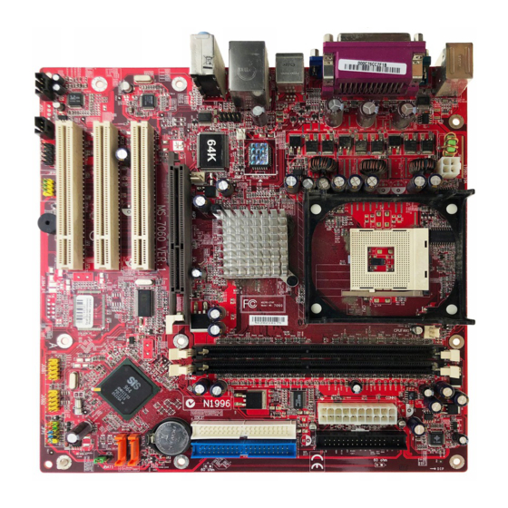
Page 12: Mainboard Layout
MS-7060 Micro ATX Mainboard Mainboard Layout Top : mouse Bottom: keyboard JPW1 Top : Parallel Port Bottom: COM port VGA port Top: 1394 port (Optional) Bottom: USB ports Top: LAN Jack JCI1 Bottom: USB ports Winbond Line-In JCOM1 W83697HF Line-Out SYSFAN1 Realtek 8201BL... -
Page 13: Chapter 2. Hardware Setup
Chapter 2. Hardware Setup Hardware Setup This chapter tells you how to install the CPU, memory modules, and expansion cards, as well as how to setup the jumpers on the mainboard. It also provides the instructions on connecting the peripheral devices, such as the mouse, keyboard, etc. -
Page 14: Quick Components Guide
MS-7060 Micro ATX Mainboard Quick Components Guide JPW1, p.2-9 Back Panel I/O, p.2-10 JCOM1, p.2-18 JCI1, p.2-19 SYSFAN1, p.2-15 PCI Slots, p.2-23 JCD1, p.2-20 JSP1, p.2-21 JAUD1, p.2-20 JFP2, p.2-19 CPUFAN1, p.2-15 CPU, p.2-3 CONN1, p.2-9 AGP Slot, p.2-23 J1394_2, p.2-18 JUSB1, p.2-21 JUSB2, p.2-21 DDR DIMMs, p.2-7... -
Page 15: Central Processing Unit: Cpu
Memory Speed/CPU FSB Support Matrix Memory 400 MHz 533 MHz 800 MHz MSI Reminds You... Overheating Overheating will seriously damage the CPU and system. Always make sure the cooling fan can work properly to protect the CPU from overheating. Replacing the CPU While replacing the CPU, always turn off the ATX power supply or unplug the power supply’s power cord from grounded outlet first to ensure the... -
Page 16: Cpu Installation Procedures For Socket 478
MS-7060 Micro ATX Mainboard CPU Installation Procedures for Socket 478 1. Please turn off the power and unplug the power cord before installing the CPU. 2. Pull the lever sideways away from the socket. Make sure to raise the lever up to a 90-degree angle. -
Page 17: Installing The Cpu Fan
CPU cooling fan and heatsink on top of the CPU. Follow the instructions below to install the Heatsink/Fan: 1. Locate the CPU and its retention mechanism on the motherboard. retention mechanism 3. Mount the fan on top of the heatsink. - Page 18 MS-7060 Micro ATX Mainboard 5. Connect the fan power cable from the mounted fan to the 3-pin fan power connector on the board. fan power cable NOTES...
-
Page 19: Memory
The mainboard provides two 184-pin unbuffered DDR266/DDR333/DDR400 DDR SDRAM, and supports the memory size up to 2GB without ECC. To operate properly, at least one DIMM module must be installed. (For the updated supporting memory modules, please visit http://www.msi.com.tw/ program/products/mainboard/mbd/pro_mbd_trp_list.php ) DDR DIMM Slots... -
Page 20: Ddr Module Combination
3. The plastic clip at each side of the DIMM slot will automatically close. MSI Reminds You... You can barely see the golden finger if the module is properly inserted in the socket. -
Page 21: Power Supply
CONN1 ATX 12V Power Connector: JPW1 This 12V power connector is used to provide power to the CPU. JPW1 MSI Reminds You... Power supply of 300-watt (and above) is highly recommended for system stability. Power Supply CONN1 Pin Definition SIGNAL 3.3V... -
Page 22: Back Panel
MS-7060 Micro ATX Mainboard The back panel provides the following connectors: Parallel Mouse Keyboard COM Port Mouse Connector The mainboard provides a standard PS/2 ® mouse. You can plug a PS/2 location and pin assignments are as follows: PS/2 Mouse (6-pin Female) 2-10 Back Panel 1394... -
Page 23: Keyboard Connector
Keyboard Connector The mainboard provides a standard PS/2 PS/2 keyboard. You can plug a PS/2 ® PS/2 Keyboard (6-pin Female) USB Connectors The mainboard provides a UHCI (Universal Host Controller Interface) Universal Serial Bus root for attaching USB devices such as keyboard, mouse or other USB-compatible devices. -
Page 24: Serial Port Connector
MS-7060 Micro ATX Mainboard Serial Port Connector The mainboard offers one 9-pin male DIN connector. It is 16550A high speed communi- cation port that sends/receives/ 16 bytes FIFOs. You can attach a serial mouse or other serial device directly to it. 1 2 3 4 5 6 7 8 9 9-Pin Male DIN Connector... -
Page 25: Rj-45 Lan Jack
Tape player, or other audio devices. Mic is a connector for microphones. 1/8” Stereo Audio Connectors MSI Reminds You... For advanced audio application, Realtek ALC 655 is provided to offer support for 6-channel audio operation and can turn rear audio connectors from 2-channel to 4-/6-channel audio. -
Page 26: Parallel Port Connector: Lpt1
MS-7060 Micro ATX Mainboard Parallel Port Connector: LPT1 The mainboard provides a 25-pin female centronic connector as LPT. A parallel port is a standard printer port that supports Enhanced Parallel Port (EPP) and Extended Capa- bilities Parallel Port (ECP) mode. SIGNAL STROBE DATA0... -
Page 27: Connectors
System Hardware Monitor chipset on-board, you must use a specially designed fan with speed sensor to take advantage of the CPU fan control. +12V SENSOR CPUFAN1 MSI Reminds You... Always consult the vendors for proper CPU cooling fan. Connectors FDD1 SENSOR... -
Page 28: Hard Disk Connectors: Ide1 & Ide2
IDE2 (Secondary IDE Connector) IDE2 can also connect a Master and a Slave drive. MSI Reminds You... If you install two hard disks on cable, you must configure the second drive to Slave mode by setting its jumper. Refer to the hard disk documentation supplied by hard disk vendors for jumper setting instructions. -
Page 29: Serial Ata Hdd Connectors: Sata1 & Sata2
1.0 specifications. Each Serial ATA connector can connect to 1 hard disk drive. SATA2 SATA1 Optional Serial ATA cable MSI Reminds You... Please do not fold the Serial ATA cable into 90-degree angle. Otherwise, the loss of data may occur during transmission. Hardware Setup... -
Page 30: Ieee 1394 Connector: J1394_2 (Optional)
MS-7060 Micro ATX Mainboard IEEE 1394 Connector: J1394_2 (Optional) The mainboard provides one IEEE1394 pin header that allows you to connect IEEE 1394 ports via an external IEEE1394 bracket (optional). J1394_2 Connected to J1394_2 Foolproof design Serial Port Connector: JCOM1 The mainboard offers one serial port JCOM1. -
Page 31: Chassis Intrusion Switch Connector: Jci1
Chassis Intrusion Switch Connector: JCI1 This connector is connected to 2-pin connector chassis switch. If the Chassis is open, the switch will be short. The system will record this status. To clear the warning, you must enter the BIOS setting and clear the status. CINTRU Front Panel Connectors: JFP1 &... -
Page 32: Cd-In Connector: Jcd1
HP_ON AUD_FPOUT_L AUD_RET_L MSI Reminds You... If you don’t want to connect to the front audio header, pins 5 & 6, 9 & 10 have to be jumpered in order to have signal output directed to the rear audio ports. Otherwise, the Line-Out connector on the back panel will not function. -
Page 33: Front Usb Connectors: Jusb1 & Jusb2
Front USB Connectors: JUSB1 & JUSB2 The mainboard provides two USB 2.0 pin headers JUSB1/JUSB2 that are compliant with Intel I/O Connectivity Design Guide. USB 2.0 technology increases data transfer ® rate up to a maximum throughput of 480Mbps, which is 40 times faster than USB 1.1, and is ideal for connecting high-speed USB interface peripherals such as USB HDD, digital cameras, MP3 players, printers, modems and the like. -
Page 34: Jumper
MS-7060 Micro ATX Mainboard The motherboard provides the following jumpers for you to set the computer’s function. This section will explain how to change your motherboard’s function through the use of jumpers. Clear CMOS Jumper: JBAT1 There is a CMOS RAM on board that has a power supply from external battery to keep the data of system configuration. -
Page 35: Slots
The motherboard provides one AGP slot, three 32-bit PCI bus slots. AGP (Accelerated Graphics Port) Slot The AGP slot allows you to insert the AGP graphics card. AGP is an interface specifi- cation designed for the throughput demands of 3D graphics. It introduces a 66MHz, 32- bit channel for the graphics controller to directly access main memory. -
Page 36: Chapter 3. Bios Setup
An error message appears on the screen during the system booting up, and requests you to run SETUP. You want to change the default settings for customized features. MSI Reminds You... 1. The items under each BIOS category described in this chapter are under continuous update for better system performance. Therefore, the description may be slightly different from the latest BIOS and should be held for reference only. -
Page 37: Entering Setup
MS-7060 Micro ATX Mainboard Power on the computer and the system will start POST (Power On Self Test) process. When the message below appears on the screen, press <DEL> key to enter Setup. Press DEL to enter SETUP If the message disappears before you respond and you still wish to enter Setup, restart the system by turning it OFF and On or pressing the RESET button. -
Page 38: Getting Help
<F1>. The Help screen lists the appropriate keys to use and the possible selections for the highlighted item. Press <Esc> to exit the Help screen. MSI Reminds You... The items under each BIOS category described in this chapter are under continuous update for better system performance. Therefore, the description may be slightly different from the latest BIOS and should be held for reference only. -
Page 39: The Main Menu
MS-7060 Micro ATX Mainboard The Main Menu Once you enter Award BIOS CMOS Setup Utility, the Main Menu (figure below) will ® appear on the screen. The Main Menu allows you to select from twelve setup functions and two exit choices. Use arrow keys to select among the items and press <Enter> to accept or enter the sub-menu. - Page 40 BIOS Setup Load Fail-Safe Defaults Use this menu to load the BIOS values for the best system performance, but the system stability may be affected. Load Optimized Defaults Use this menu to load factory default settings into the BIOS for stable system perfor- mance operations.
-
Page 41: Standard Cmos Features
MS-7060 Micro ATX Mainboard Standard CMOS Features The items in Standard CMOS Features Menu are divided into 11 categories. Each category includes no, one or more than one setup items. Use the arrow keys to highlight the item and then use the <PgUp> or <PgDn> keys to select the value you want in each item. - Page 42 If you select [Manual], related information is asked to be entered to the following items. Enter the information directly from the keyboard. This information should be provided in the documentation from your hard disk vendor or the system manufacturer. Access Mode Capacity Cylinder Head...
-
Page 43: Advanced Bios Features
MS-7060 Micro ATX Mainboard Advanced BIOS Features Quick Boot Setting the item to [Enabled] allows the system to boot within 5 seconds since it will skip some check items. Setting options: [Disabled], [Enabled]. Full Screen LOGO Show This item enables you to show the company logo on the bootup screen. Settings are: [Enabled] Shows a still image (logo) on the full screen at boot. - Page 44 Setting options: [Auto], [Enabled], [Disabled]. MSI Reminds You... 1. Available settings for “1st/2nd/3rd Boot Device” vary depending on the bootable devices you have installed. For example, if you did not install a floppy drive, the setting “Floppy”...
- Page 45 To find out which version to use, consult the vendor of your operating system. Setting options: [1.4], [1.1]. MSI Reminds You... Enabling the functionality of Hyper-Threading Technology for your com- puter system requires ALL of the following platform Components:...
-
Page 46: Advanced Chipset Features
Advanced Chipset Features MSI Reminds You... Change these settings only if you are familiar with the chipset. DRAM Clock/Timing Control Press <Enter> and the following sub-menu appears: Current CPU/DRAM/DDR Frequency These items allow you to view the current CPU/DRAM/DDR frequency. - Page 47 MS-7060 Micro ATX Mainboard DRAM Timing Control This field allows you to select the DRAM timing setting. Setting to [By SPD] enables Max Memclock (Mhz) automatically to be determined by SPD. Selecting [Manual] allows users to configure these fields manually. DRAM CAS Latency When the DRAM Timing Control is set to [Manual], this field is adjustable.
- Page 48 AGP & P2P Bridge Control Press <Enter> and the following sub-menu appears: AGP Aperture Size This setting controls just how much system RAM can be allocated to AGP for video purposes. The aperture is a portion of the PCI memory address range dedicated to graphics memory address space.
-
Page 49: Integrated Peripherals
MS-7060 Micro ATX Mainboard Integrated Peripherals SiS OnChip IDE Device Press <Enter> and the following sub-menu appears: Internal PCI/IDE The field specifies the internal primary and secondary PCI/IDE controllers. Setting options: [Disabled], [Primary], [Secondary], [Both]. IDE Primary/Secondary Master/Slave PIO The four IDE PIO (Programmed Input/Output) fields let you set a PIO mode (0-4) for each of the four IDE devices that the onboard IDE interface supports. - Page 50 IDE DMA transfer access Setting to [Enabled] will open DMA bus master and execute DMA action in DOS, which will make the data transferring faster. Setting options: [Disabled], [Enabled]. SiS OnChip PCI Device Press <Enter> and the following sub-menu appears: SiS USB Controller Select [Enabled] if your system contains a Universal Serial Bus (USB) controller and you have USB peripherals.
- Page 51 MS-7060 Micro ATX Mainboard Onboard SuperIO Device Press <Enter> and the following sub-menu appears: Onboard FDC Controller Select [Enabled] if your system has a floppy disk controller (FDD) installed on the system board and you wish to use it. If you install add-on FDC or the system has no floppy drive, select [Disabled] in this field.
-
Page 52: Power Management Setup
Power Management Setup ACPI Function This item is to activate the ACPI (Advanced Configuration and Power Management Interface) function. If your operating system is ACPI-aware, such as Windows 98SE/ 2000/ME, select [Enabled]. Setting options: [Enabled], [Disabled]. Sleep State This item specifies the power saving modes for ACPI function. Options are: [S1/POS] The S1 sleep mode is a low power state. - Page 53 MS-7060 Micro ATX Mainboard MODEM Use IRQ This setting names the interrupt request (IRQ) line assigned to the modem (if any) on your system. Activity of the selected IRQ always awakens the system. Setting options: [3], [4], [5], [7], [9], [10], [11], [Auto]. Hot Key Function As This setting specifies the function of the preset hot key (Ctrl+Alt+Backspace).
- Page 54 PS2MS Wakeup From S3/S4/S5 This controls how the PS/2 mouse can power on the system. Setting options: [Click], [Move & Click], [Disabled]. MSI Reminds You... S3-related functions described in this section are available only when your BIOS supports S3 sleep mode.
-
Page 55: Time (Hh:mm:ss) Alarm
MS-7060 Micro ATX Mainboard Resume By Alarm The field is used to enable or disable the function of Resume By Alarm. Setting options: [Disabled], [Enabled]. Month Alarm When Resume By Alarm is set to Enabled, the field specifies the month for Resume By Alarm. -
Page 56: Pnp/Pci Configurations
BIOS Setup PNP/PCI Configurations This section describes configuring the PCI bus system and PnP (Plug & Play) feature. PCI, or Peripheral Component Interconnect, is a system which allows I/O devices to operate at speeds nearing the speed the CPU itself uses when communicating with its special components. - Page 57 MS-7060 Micro ATX Mainboard IRQ Resources The items are adjustable only when Resources Controlled By is set to Manual. Press <Enter> and you will enter the sub-menu of the items. IRQ Resources list IRQ 3/4/5/7/9/10/11/12/14/15 for users to set each IRQ a type depending on the type of device using the IRQ.
-
Page 58: Pc Health Status
BIOS Setup PC Health Status This section shows the status of your CPU, fan, overall system status, etc. Monitor function is available only if there is hardware monitoring mechanism onboard. Smart Fan Target Temp. ( W83697HF provides the Smart Fan system which can control the fan speed automati- cally depending on the current temperature to keep it with in a specific range. -
Page 59: Frequency/Voltage Control
(EMI). Setting options: [Enabled], [Disabled]. Spread Spectrum When the motherboard’s clock generator pulses, the extreme values (spikes) of the pulses creates EMI (Electromagnetic Interference). The Spread Spectrum function reduces the EMI generated by modulating the pulses so that the spikes of the pulses are reduced to flatter curves. -
Page 60: Load Fail-Safe/Optimized Defaults
BIOS Setup Load Fail-Safe/Optimized Defaults The two options on the main menu allow users to restore all of the BIOS settings to the default Fail-Safe or Optimized values. The Optimized Defaults are the default values set by the mainboard manufacturer specifically for optimal performance of the mainboard. The Fail-Safe Defaults are the default values set by the BIOS vendor for stable system performance. -
Page 61: Set Supervisor/User Password
Security Option of the Advanced BIOS Feature menu. If the Security Option is set to [System], the password is required both at boot and at entry to Setup. If set to [Setup], password prompt only occurs when you try to enter Setup. MSI Reminds You... About Supervisor Password & User Password: Supervisor password:... -
Page 62: Chapter 4. Introduction To Sis964 Sata Raid
Mirroring increases read performance through load balanc- ing and elevator sorting while creating a complete backup of your files. Span would increase the logic hard disk space. MSI Reminds You... All the information/volumes listed in your system might differ from the illustrations in this appendix. -
Page 63: Introduction
MS-7060 Micro ATX Mainboard System Requirement Operating System Support Microsoft Windows 98 Second Edition Microsoft Windows ME Microsoft Windows 2000 Professional and Server Microsoft Windows XP RAID Basics This section will give you an overview about the RAID system and introduce the basic background and glossary which you need to know before using “SiS RAID Controller Application”. -
Page 64: Raid 0 (Striping Array)
RAID 0 (Striping array) Any combination to 2, 3 or 4 Hard disks would combine to a stripe system. HDD Population Rules for RAID 0 (Striping) Ultra ATA (Master) Ultra ATA (Slave) Serial ATA (Master 1) Serial ATA (Master 2) V = Selected;... -
Page 65: System Bios Setup
MS-7060 Micro ATX Mainboard System BIOS Setup Power on the computer and the system will start POST (Power On Self Test) process. When the message below appears on the screen, press <DEL> key to enter Setup. For Award BIOS: Press DEL to enter SETUP If the message disappears before you respond and you still wish to enter Setup, restart the system by turning it OFF and On or pressing the RESET button. -
Page 66: Bios Configuration
BIOS Configuration Starting BIOS Utility 1. Boot your system. If this is the first time you have booted with the SiS964 and the drives installed, the BIOS will display the following screen: Silicon Integrated Systems Corp. RAID BIOS Setting Utility v1.04_964 (c) 2003-2005 Silicon Integrated Systems Corp. - Page 67 MS-7060 Micro ATX Mainboard 2. Press <Ctrl-S> keys to display the SiS964 Utility Main Menu. 3. Press <R> to display the RAID setup menu below. This is the fastest and easiest method to create your first array. The [A] and [D] key will appear randomly in the different conditions.
- Page 68 Introduction to SiS964 SATA RAID [b]. No available disk existing but have RAID existing: [c]. Available disks and RAID existing simultaneously: 4 - 7...
-
Page 69: Create A Raid 0 (Stripe) Array For Performance
MS-7060 Micro ATX Mainboard [d]. Available disk is not enough to create RAID: Create a RAID 0 (Stripe) Array for performance To create an array for best performance, please follow these steps: 1. Press <A> to start creating a RAID array. 2. - Page 70 Introduction to SiS964 SATA RAID 3. You will have two selections to create a RAID 0 array. The default value is <1>. If you select <1>Auto Create, you can create a RAID 0 array faster and easier. The Blocksize will be selected by its default value “64K”. The result after auto creating will be shown on step 6.
- Page 71 MS-7060 Micro ATX Mainboard 5. Use < > < > to select disk , and press <Enter> to select disk, <Q> to exit. When you press <Enter> on the disk you wanted, the RAID Type will be changed from Single to RAID 0. And the disk you select first will be the SOURCE disk. 6.
- Page 72 Introduction to SiS964 SATA RAID 7. Starting splitting action, the following frame will be shown. 8. After all steps finished, press <Q> until escape the setup menu and RAID 0 array will be shown on the top of the main frame. 4-11...
-
Page 73: Create A Raid 1 (Mirror) Array For Performance
MS-7060 Micro ATX Mainboard 9. Press <Q> until exit this BIOS utility and the red message frame will show. Press <Y> and <Enter> to save changes. 10. Once the array has been created, you will need to FDISK and FORMAT the array as if it were a new single hard drive. - Page 74 Introduction to SiS964 SATA RAID 3. You will have two selections to create a RAID 1 array. The default value is <1>. If you select <1>Auto Create, you can create a RAID 1 array faster and easier. The result after creating will be shown on step 5. Besides, you also can select <2> Manual Create, see following steps.
- Page 75 MS-7060 Micro ATX Mainboard 5. Next, you will see a message “Duplicate the SOURCE(Disk x) data to RAID disks?”. Press <N> and <Enter> to create RAID 1 array only or press <Y> and <Enter> to duplicate the data from source disk to mirror disk. 6.
- Page 76 Introduction to SiS964 SATA RAID 7. After all steps finished, press <Q> until escape the setup menu and RAID 1 array will be shown on the top of the main frame. 8. Press <Q> until exit this BIOS utility and the red message frame will show as the same as the creation of the RAID 0 array.
-
Page 77: Create A Jbod Array For Performance
MS-7060 Micro ATX Mainboard Create a JBOD Array for performance To create a JBOD array for best performance, please follow these steps: 1. Press <A> to start creating a RAID array. 2. Press <1> and <Enter> to select JBOD. 3. You will have two selections to create a JBOD array. The default value is <1>. If you select <1>Auto Create, you can create a JBOD array faster and easier. - Page 78 Introduction to SiS964 SATA RAID 4. Use< > < > to select disk , and press <Enter> to select disk, <Q> to exit. When you press <Enter> on the disk you wanted, the RAID Type will be changed from Single to JBOD. 5.
-
Page 79: Delete A Raid Array
MS-7060 Micro ATX Mainboard Delete a RAID array 1. After enter the SiS964 Utility Main Menu, press <R> to display the RAID setup menu below. This is the fastest and easiest method to delete your first array. 2. Press <D> to start deleting a RAID array, and use< > < > to select RAID array you wanted to delete. - Page 80 Introduction to SiS964 SATA RAID 3. Press <Enter> to select the RAID array that you want to delete. And a message “Are you sure to delete this RAID?” will show on this frame. 4. Press <Y> and <Enter>, the deleting action finish. And the RAID Type of all disk members of this RAID array will be changed from RAID 0 to Single.
- Page 81 MS-7060 Micro ATX Mainboard 5. Press <Q> until escape the BIOS Utility, and the red message frame will show on it. 6. Press <Y> and <Enter> to save all changes. 4-20...
-
Page 82: Installing Software
(The information of this driver diskette exists in MSI CD. Please prepare for one formatted floppy disk to copy the contents in the Floppy folder of the following access: Insert MSI CD and start the menu --> click IDE folder --> SIS --> 180RAID --> Floppy) 4. -
Page 83: Installation Of Sis Sata Raid Driver
South Bridge SiS964 SATA controller support Serial ATA w/ RAID0, RAID 1 and JBOD by installing SiS RAID driver. Insert the MSI CD and click on the SiS SATA RAID Driver to install the software. Click on this item 4-22... -
Page 84: Appendix: Using 4- Or 6-Channel Audio
Appendix: Using 4- or 6-Channel Audio Function The motherboard is equipped with Realtek ALC655 chip, which provides support for 6-channel audio output, including 2 Front, 2 Rear, 1 Center and 1 Subwoofer channel. ALC655 allows the board to attach 4 or 6 speakers for better surround sound effect. -
Page 85: Installing The Audio Driver
2. Click Realtek AC97 Audio Drivers. MSI Reminds You... The AC97 Audio Configuration o u s u p d a t e t o e n h a n c e a u d i o screens shown here in this appendix may be slightly different from the latest software utility and shall be held for reference only. - Page 86 3. Click Next to start installing files into the system. 4. Click Finish to restart the system. Using 4- or 6-Channel Audio Function Select this option...
-
Page 87: Using 4- Or 6-Channel Audio Function
MS-7060 Micro ATX Mainboard Using 4- or 6-Channel Audio Function After installing the audio driver, you are able to use the 4-/6-channel audio feature now. To enable 4- or 6-channel audio operation, first connect 4 or 6 speakers to the appropriate audio connectors, and then select 4- or 6-channel audio setting in the software utility. - Page 88 Using 4- or 6-Channel Audio Function...
-
Page 89: Connecting The Speakers
MS-7060 Micro ATX Mainboard Connecting the Speakers When you have set the Multi-Channel Audio Function mode properly in the soft- ware utility, connect your speakers to the correct phone jacks in accordance with the setting in software utility. 2-Channel Mode for Stereo-Speaker Output Refer to the following diagram and caption for the function of each phone jack on the back panel when 2-Channel Mode is selected. - Page 90 4-Channel Mode for 4-Speaker Output The audio jacks on the back panel always provide 2-channel analog audio output function, however these audio jacks can be transformed to 4- or 6- channel analog audio jacks by selecting the corresponding multi-channel operation from No. of Speakers. Refer to the following diagram and caption for the function of each jack on the back panel when 4-Channel Mode is selected.
- Page 91 Line Out func- tion when 6-Channel Mode for 6-Speaker Output is selected. MSI Reminds You... If the Center and Subwoofer speaker exchange their audio channels when you play video or music on the computer, a converter may be required to exchange center and subwoofer audio signals.
-
Page 92: Testing The Connected Speakers
Front Left Rear Left MSI Reminds You... 6 speakers appear on the “Speaker Test” window only when you select “6-Channel Mode” in the “No. of Speakers” column. If you select “4- Channel Mode”, only 4 speakers appear on the window. - Page 93 MS-7060 Micro ATX Mainboard 4. While you are testing the speakers in 6-Channel Mode, if the sound coming from the center speaker and subwoofer is swapped, you should select Swap Center/ Subwoofer Output to readjust these two channels. Select this function A-10...
-
Page 94: Playing Karaok
Using 4- or 6-Channel Audio Function Playing KaraOK The KaraOK function will automatically remove human voice (lyrics) and leave melody for you to sing the song. Note that this function applies only for 2-channel audio operation. Playing KaraOK 1. Click the audio icon from the window tray at the lower-right corner of the screen.
Need help?
Do you have a question about the 661FM2-V ILSR and is the answer not in the manual?
Questions and answers