
Related Manuals for Atlas Copco Pulsor C


Summary of Contents for Atlas Copco Pulsor C
- Page 1 User Guide Pulsor C Pulsor C System manual Atlas Copco Tools and Assembly Systems 9836 4841 01 Software release 5.9 2011-10 Edition 4.1...
- Page 3 Contents – chapter overview Contents - chapter overview Part I: Getting started with Pulsor C Introduction to Pulsor C Connecting and installing the Pulsor system Introducing the Pulsor system's user interface Tool Control box and tool introduction Performing Tool Setup...
-
Page 4: Table Of Contents
Overview of the Pulsor system................. 11 Pulsor components....................14 Pulsor accessories ....................16 Connecting and installing the Pulsor C system ..........17 Required hardware and software ................17 Connect the physical parts of the system..............18 Install the ToolsTalk Pulsor C software ..............18 Initial connection of ToolsTalk Pulsor............... - Page 5 Contents 5.7.2 Performing Tool Setup from Pulsor Focus front panel ..........35 Changing parameters after a Tool Setup..............36 5.8.1 Changing Torque Tuning..................36 5.8.2 Changing Control parameters .................36 Working with ToolsTalk Pulsor................37 Connecting the computer to Pulsor Focus..............37 6.1.1 Connecting via USB cable..................37 6.1.2 Connecting via serial cable..................38 6.1.3...
- Page 6 Contents Completing Monitoring Setup ................... 65 Result values from a Monitoring Setup ..............66 Making Monitoring Setup via Pulsor Focus front panel ..........67 Job........................68 10.1 Creating a standalone Job ..................69 10.2 Creating Multi Pulsor Focus Jobs................71 10.3 Running Jobs ......................71 10.3.1 Running Jobs using ToolsTalk Pulsor ..............
- Page 7 Contents 13.3.2 TCB air hose test.....................89 13.4 Maintenance ......................90 13.4.1 Tool service and Service indicator ................90 13.4.2 Tool drift alarm......................91 13.5 Air sensor tuning.......................95 Identifier .......................97 14.1 Barcode data string....................97 14.2 Identifier setup ......................98 FieldBus ......................100 15.1 General setup ......................100 15.1.1 Parameters in General setup.................101 15.2 From/To PF setup....................102...
- Page 8 Contents 20.4 Stacklight........................ 126 20.4.1 Setting up a stack light using ToolsTalk ............... 127 20.5 RE-Alarm........................ 129 20.5.1 Setup of RE-Alarm....................129 20.6 Other accessories ....................129 20.6.1 Barcode reader ..................... 129 20.6.2 Operator panel...................... 129 Configurable memory ..................130 21.1 Configurable memory conditions................130 21.2 ToolsTalk Pulsor operations...................
- Page 9 Contents 23.4.3 D3xx System diagnostics ..................160 23.4.4 23.4.5 D9xx Tool Drift alarm.....................161 23.5 Identifier ........................162 23.5.1 I1xx Identifier setup ....................162 23.6 FieldBus........................162 RBU information....................165 24.1 RBU functionality ....................166 24.2 Connecting the RBU ....................167 24.3 Start-up instructions....................167 Pulsor Focus hardware description ..............169 25.1 Physical data ......................169 25.1.1 Dimension drawing ....................169...
- Page 10 Contents 30.6 DeviceNet....................... 199 30.6.1 DeviceNet for Pulsor Focus .................. 199 30.7 InterBus ........................203 30.7.1 InterBus for Pulsor Focus ..................203 30.8 ModBusPlus ......................206 30.8.1 ModBusPlus for Pulsor Focus ................206 30.9 EtherNet ......................... 210 30.9.1 EtherNet for Pulsor Focus ..................210 30.10 Profinet ........................
-
Page 11: Introduction To Pulsor C
Description Part I Getting started with Pulsor C – This part introduces Pulsor C and is also a step by step instruction on how to get chapter 1-5 to the point of doing real tightenings with your Pulsor C system. - Page 12 Introduction to Pulsor C Ideal pulse (calculated) Ideal pulse (calculated) Real pulse Real pulse torque torque Target torque Target torque Pulsor Control Pulsor Control The regulator controls the The regulator controls the Current pressure Current pressure pressure for each pulse for pressure for each pulse for best accuracy.
- Page 13 Introduction to Pulsor C The main features of Pulsor C are: Functions Description Tool setup Pulsor C features an easy to use to help you get ready to use the system as quickly as Tool Setup possible. By performing a couple of tightenings and telling the system what torque is actually achieved, the system parameters are automatically set to appropriate values.
-
Page 14: Pulsor Components
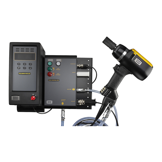
RBU. ToolsTalk This software offers simple and user-friendly system setup and monitoring of the Pulsor Pulsor Focus units in real time. All settings in the Pulsor C system can be set from ToolsTalk Pulsor. 14 (223) 9836 4841 01... - Page 15 Introduction to Pulsor C The following is an illustration of a standard configuration of a Pulsor system: Pulsor Focus controller RBU (backside of Tool Control Box Pulsor Focus) Air hose Tool cable ToolsTalk Tool Pulsor Cable to PC Serial / Ethernet See chapter 25, Pulsor Focus hardware description for detailed information about the Pulsor Focus connections.
-
Page 16: Pulsor Accessories
Introduction to Pulsor C Pulsor accessories A number of external accessories are available for the Pulsor C system. The following are the most important: Product Name Description Selector Selector is a socket rack that selects which Pset (parameter set) the tool shall use. -
Page 17: Connecting And Installing The Pulsor C System
Connecting and installing the Pulsor C system Connecting and installing the Pulsor C system This chapter will take you through connecting and installing the Pulsor C system. The major steps are: • Make sure that all required hardware and software is included. -
Page 18: Connect The Physical Parts Of The System
Connecting and installing the Pulsor C system Connect the physical parts of the system Wall Lock Pulsor Focus Before performing step 9 below, make sure the Tool Control Box is fit with the correct air sockets. A socket that is “locked” when no air hose is connected, i.e. a female socket, must be used for the Tool Control Box air outlet to the tool. -
Page 19: Initial Connection Of Toolstalk Pulsor
• From ToolsTalk Pulsor C, first connect serially as described above. Then, go to Communication under Config (see chapter 11.1, Introduction to Config and 11.3, Network for more information on how to do this). Set the IP address, subnet mask and, where applicable, the default gateway. Store and restart Pulsor Focus. -
Page 20: Exchange Of Tools (Hot Swap)
Connecting and installing the Pulsor C system Exchange of tools (Hot swap) You can exchange tools while the system is on (Hot swap) even if the system is connected to ToolsTalk Pulsor. 20 (223) 9836 4841 01... -
Page 21: Introducing The Pulsor System's User Interface
Introducing the Pulsor system’s user interface Introducing the Pulsor system’s user interface Signal lights on the tool The tool has three signal lights – green, yellow and red. Color Description Green Tightening approved. Flashing red Active monitoring parameter is exceeded. Flashing yellow An active monitoring parameter is below limits and/or the operator has released the trigger before tool shut- off. -
Page 22: Pulsor Focus Front Panel
Introducing the Pulsor system’s user interface Pulsor Focus front panel The front panel of the Pulsor Focus consists of a display, indicator lights, buttons and a red and white power switch. Pulsor Focus front panel Pulsor Focus front panel Indicator Indicator lights lights... -
Page 23: Indicator Lights
Introducing the Pulsor system’s user interface 3.3.1 Indicator lights Light Indicator light Description The OK light indicates that the result of the tightening is within the specified limits. The indicator remains active until the next tightening starts. The NOK red light indicates that the result of the tightening falls outside the specified limits. The light is active until the next tightening starts. -
Page 24: Keys
Introducing the Pulsor system’s user interface 3.3.2 Keys Function Function Pset Setup Pset Setup Enter Enter Description Plus (+) Navigates through menus on the display and increase numbers. Minus (-) Navigate through menus on the display and decrease numbers. Function (F) Press F (Function button) to display functions F1 –... -
Page 25: Toolstalk Pulsor
Introducing the Pulsor system’s user interface Description Press Enter to create and select the Pset. Press F to exit (no save). F7 - Torque Tuning adjustment – set new measured torque “F7”/”nEtq” alternates on the display. Press Enter to access the Torque tuning value. The value shown is equal to the target torque for the Pset. Press the +/- buttons to change this value to the mean torque achieved during recent tightenings. -
Page 26: Tool Control Box And Tool Introduction
The Air Hose Test The Pulsor C system supports air hose lengths of up to 10 meters between TCB and tool. It may work with a longer hose, but the quality of the tightenings will decrease when using a long hose. -
Page 27: Starting Air Hose Test From Tool Control Box
Tool Control Box and tool introduction 4.1.3 Starting Air Hose Test from Tool Control Box The white TCB button is by default set to start an Air Hose Test. The functions associated with the TCB buttons can be changed from ToolsTalk Pulsor. 4.1.4 Lights The TCB features two signal lights, one green and one red. -
Page 28: The Tool
Tool Control Box and tool introduction The tool Consult www.atlascopco.com/tools for the latest list of available tools. Recommended air hose diameters for the tools available when this manual is printed are: Tool size Air hose diameter EPP6C32 – EPP10C90 10 mm EPP11C110 –... -
Page 29: Performing Tool Setup
The Torque Tuning Factor translates the torque recognized by the tool into the actual torque installed in the joint. To perform a Tool Setup, you will need a Pulsor C system, test joints (the actual application joints) and your preferred torque measurement tool e.g. torque wrench or inline torque transducer. -
Page 30: Starting Tool Setup From Toolstalk, Method 2
Performing Tool Setup 5.2.2 Starting Tool Setup from ToolsTalk, method 2 Make sure the correct Pset is activated and that the Pset window for that Pset is open. Start Tool Setup by clicking the Perform Tool Setup button, located in the Pset window, Programming->Tool Setup. If the correct Pset is active, the Tool Setup window will be shown. -
Page 31: Tool Setup Monitor
Performing Tool Setup Tool Setup Monitor In the Tool Setup Monitor all tightenings performed during Tool Setup will be shown. The tightenings you perform and the measured torque values you enter in this window will help the system determine how to reach the target at the desired speed. -
Page 32: Making Tool Setup Tightenings, Toolstalk Pulsor
Performing Tool Setup to write in measured torque and press Apply after each representative tightening. The Apply button will be greyed out before the first tightening is performed. By pressing the button a torque over time graph will appear on the right hand side of the Tool Traces Setup Monitor window. -
Page 33: Deletion Of Tool Setup Tightenings
Performing Tool Setup A Tool Setup can be performed without writing in any measured torque value at all, although this is not recommended. In such cases the Torque Tuning factor is set to 1, i.e. the basic calculated torque value will be used. -
Page 34: Manual Tool Setup
Performing Tool Setup Manual Tool Setup If the joint is particularly difficult the Tool Setup may fail to find the correct parameters. In this case you can perform a manual Tool Setup. Start Tool Setup as usual. Set Tightening Strategy, Target Torque and Speed. -
Page 35: Performing Tool Setup From Pulsor Focus Front Panel
Performing Tool Setup 5.7.2 Performing Tool Setup from Pulsor Focus front panel Note that the Pulsor Control strategy will always be used when performing Tool Setup from the Pulsor Focus front panel. Press the Pset Setup button once. If no Tool Setup has been done for this Pset previously, air hose test will be performed and Tool Setup is started. -
Page 36: Changing Parameters After A Tool Setup
Performing Tool Setup Changing parameters after a Tool Setup The settings mentioned below can be found in the Pset window for the actual Pset. 5.8.1 Changing Torque Tuning After a Tool Setup has been performed all necessary parameters for the current application are stored in the Pset. -
Page 37: Working With Toolstalk Pulsor
Working with ToolsTalk Pulsor Working with ToolsTalk Pulsor This chapter describes how to connect your computer to the Pulsor Focus and how to use ToolsTalk Pulsor. Connecting the computer to Pulsor Focus The computer can be connected to the Pulsor Focus by using any of the following options: 1. -
Page 38: Connecting Via Serial Cable
Connecting via serial cable Connect your computer to the Pulsor Focus with an Atlas Copco serial cable. The serial port can be found on the backside of the Pulsor Focus, serial port #2. No special installation has to be done. Jump to chapter 6.2, Starting ToolsTalk Pulsor for more information on how to use serial communication together with... -
Page 39: Hardware Required
Working with ToolsTalk Pulsor Hardware required • A Pulsor Focus unit. • A crossover Ethernet cable (RX/TX crossed). • A PC with an Ethernet connection (the PC shall not be connected to the network). Configuring the PC ® • Go into Windows network settings (e.g. - Page 40 Working with ToolsTalk Pulsor Start on the PC for example by double- ToolsTalk Pulsor clicking on the ToolsTalk Pulsor icon on your desktop. If running the demo version, select Continue evaluation or select to register now. Register Connect to Pulsor Focus by either: •...
-
Page 41: Toolstalk Pulsor User Interface
Working with ToolsTalk Pulsor ToolsTalk Pulsor user interface The figure below shows the principal areas in ToolsTalk Pulsor’s user interface: Menu row Menu row Selection panel Selection panel Toolbar Toolbar PF Map PF Map There are several ways to start a function in ToolsTalk Pulsor. Generally, all functions can be reached by a menu item in the menu row, by clicking on a tool button in the toolbar or by double clicking on the item in the PF Map. -
Page 42: Selection Panel
Working with ToolsTalk Pulsor 6.3.2 Selection panel Name Description Selected Controller The following options are available: Serial connection, Ethernet connection or Offline mode. If the selected Pset source (Config. Parameter [C222]) is in Ethernet/Serial mode you can select Pset from Running Pset this window. -
Page 43: Toolbar
Working with ToolsTalk Pulsor 6.3.3 Toolbar Icon Name Description Tool Setup Clicking this button will start Tool Setup for the active Pset. Click the arrow to the right of this button button to show a drop down list of available Psets and an option to create a new Pset. After a Pset is activated or created, the Pset will be selected and Tool Setup for that Pset will automatically be started. -
Page 44: Event Codes In Toolstalk Pulsor
Working with ToolsTalk Pulsor Event codes in ToolsTalk Pulsor There are two kinds of event codes you may get when using the Pulsor system: Types of event code Display on the front Activity from the user panel in Pulsor Focus Event codes that need The event code flashes This type of event is of such severity that it needs to be attended to before... -
Page 45: Creating A New Pset
Working with ToolsTalk Pulsor 6.5.1 Creating a new Pset Each type of joint has its own characteristics. If you want to use the tool on different joints you therefore need one Pset for each type of joint. Proceed as follows to create a new Pset: Create a new Pset by clicking the on Pset in the PF Map. -
Page 46: Settings In Toolstalk Pulsor
Working with ToolsTalk Pulsor Settings in ToolsTalk Pulsor This section describes the Settings functionality in ToolsTalk Pulsor. Select from the Options menu. Settings The Settings window has four tabs: • - Information about communication and Communication connection. • - Settings for displaying information in Application ToolsTalk Pulsor. -
Page 47: Settings - Application
Working with ToolsTalk Pulsor Via the button you can make special setup Advanced for logging. is activated the size of “log.txt”- file Split Log cannot exceed the value set in . When the Logfile size file is full the file will be renamed to “log~.txt” and the contents of “log.txt”... -
Page 48: Settings - Pf List
Working with ToolsTalk Pulsor 6.6.4 Settings - PF List From the tab you can manage the . You can add, modify and remove items. An item PF List PF available list is a Pulsor Focus unit with Name, IP address, port number and controller type. If you want to use multiple PF list files you can select which one you want to use. -
Page 49: Storing Programming On File
Working with ToolsTalk Pulsor Storing programming on file To store the programmed settings on file, open the menu. The following options are available: File Read . <Object> could be Pset, Job, Config, <object> Read PF from File Save <object> Store PF to File Identifier or Diagnostics depending on which corresponding window is currently active. -
Page 50: Offline Mode
Working with ToolsTalk Pulsor Offline mode mode gives the user the opportunity to conduct programming and configuration without being Offline connected to a Pulsor Focus unit. All programming will be stored to or read from a file. This file can be copied to one or more Pulsor Focus units. -
Page 51: Miscellaneous Toolstalk Pulsor Tasks
Working with ToolsTalk Pulsor Miscellaneous ToolsTalk Pulsor tasks 6.9.1 New user for an existing ToolsTalk Pulsor installation When a new user is added to the computer running ToolsTalk Pulsor, the PF List may be inaccessible due to user access rights or due to the list being stored in an unexpected folder or with an unexpected filename. This section describes how you point out the PF list you want to use for an existing ToolsTalk Pulsor installation. -
Page 52: Pset And Batch Count
Pset and batch count Pset and batch count All Pulsor tightenings are performed in the context of a (Parameter set). The Pset contains the set of Pset parameters that controls and monitors the tightening process, including the result of Tool and Monitoring Setup. -
Page 53: Control Parameters
Pset and batch count Open the relevant Pset from the PF Map. Select Tightening options under programming from the navigation area. Activate Batch count by selecting Pset from the list in and then enter the Batch count number in the Batch size field. The parameter Max coherent NOK’s will count how many NOK tightenings that may be performed consecutively until air will be shut... -
Page 54: Pset Administration
Pset and batch count regular joints, this parameter should be set to 0%. For prevailing torque joints, 40% is often a good value but this depends on the torque in the rundown pulses, the threshold should lie a bit above the torque of typical rundown pulses. -
Page 55: Tightening And Monitoring
Tightening and monitoring Tightening and monitoring This chapter describes the parameters that are measured when performing tightenings and how they can be used. Advices on what to think of and how different problems can be resolved are given. Go directly to sections 8.4, Tightening monitoring, and 8.5, Changing limits and activate monitor parameters, if you want to get started quickly and adjust the tightening monitoring. -
Page 56: A Tightening And Its Parameters
Tightening and monitoring A tightening and its parameters The above graph shows the torque (black), angle (dashed) and the air pressure at the air motor in the tool (dotted) for a typical tightening. The tightening starts (t=0) when the tool trigger is pressed. During the first 0.2 seconds the thread is run down and then the first pulse occurs and the actual tightening is started. -
Page 57: Viewing Results
Tightening and monitoring Parameter Description Pulse filter Sometimes a pulse occurs during rundown that has nothing to do with the tightening. Examples of this are when locknuts are used or the thread is damaged. The pulse filter identifies such pulses and removes them from the calculations of torque, relative angle, number of pulses, tightening time, rundown time, pulse frequency and pulse pressure. - Page 58 Tightening and monitoring Display for instructions on how to use ToolsTalk Pulsor to set the display. When using ToolsTalk Pulsor, the Tracking result monitor shows all results from the tightenings. See chapter 16, Monitors for more information. 58 (223) 9836 4841 01...
-
Page 59: Tightening Monitoring
Tightening and monitoring Tightening monitoring Monitoring is used to determine if a tightening is OK or not OK. If, after a tightening, a parameter that is monitored lies outside of its accepted interval that tightening will be rejected. How the system should react on a rejected tightening is configurable. -
Page 60: Using The Tightening Monitoring Options
Tightening and monitoring Using the tightening monitoring options A change in Tightening angle start and Rundown pulse filter will affect the values of the corresponding tightening results. If this is changed the limits for monitoring may need to be adjusted as well. Limit values, Tightening angle start and Rundown pulse filter can be changed, activated or deactivated arbitrarily at any time. -
Page 61: Analysis Of Improvements
Tightening and monitoring : If there is a risk that prevailing torque nuts (for example nyloc® nuts) are mistaken for standard Self-lock nuts or vice versa, this error can be captured using the rundown time. The rundown time is often longer for prevailing torque nuts. -
Page 62: Performing A Monitoring Setup
Performing a Monitoring Setup Performing a Monitoring Setup Introduction A Pset may be set to monitor on a lot of tightening parameters. To automatically generate suggestions for these limit parameters you can perform a Monitoring Setup. This will teach the Pset the difference between “good”... -
Page 63: Making Monitoring Setup Tightenings
Performing a Monitoring Setup Making Monitoring setup tightenings Important information regarding tightenings: • Use the tool on the actual target joint. • Perform the tightenings. • Do not release the tool trigger prematurely. The tool must shut off after each tightening (tightenings where the tool has not shut off are not included in Monitoring Setup). -
Page 64: Making Setups During Monitoring Setup
Performing a Monitoring Setup 9.3.1 Making setups during Monitoring Setup By pressing the Set reference values button you can change the following parameters while carrying out a Monitoring Setup. These parameters affect the measurement values, also for tightenings already done during Monitoring Setup. -
Page 65: Completing Monitoring Setup
Performing a Monitoring Setup Completing Monitoring Setup Check that the result from the Monitoring Setup tightenings is reasonable. Review the max/min results: Identify and delete any deviating tightenings. When enough tightenings have been made, the Accept button will be marked in yellow, or, if Tools Talk identifies a problem with the Monitoring Setup, see below. -
Page 66: Result Values From A Monitoring Setup
Performing a Monitoring Setup Result values from a Monitoring Setup When a Monitoring Setup is complete, the proposed limit values are stored in the tightening monitoring parameters. The result values from the Monitoring Setup are saved for later reference. In the window of the active Pset, click on under Monitoring View Result setup to check the saved values from Monitoring Setup. -
Page 67: Making Monitoring Setup Via Pulsor Focus Front Panel
Performing a Monitoring Setup Making Monitoring Setup via Pulsor Focus front panel It is possible to make a Monitoring Setup without ToolsTalk Pulsor, but there are some limitations. It is important to know the following when making a Monitoring Setup via the front panel. •... -
Page 68: Job
The Job function is useful when an object requires tightenings in a controlled sequence, often with more than one Pset used for the application. Instead of manually selecting the Pset you can create a Job and let Pulsor Focus keep track of the parameters that are needed to perform the task. For parameter descriptions see Parameter list, section 23.2, Job. -
Page 69: Creating A Standalone Job
10.1 Creating a standalone Job The Job creation section is accessible from ToolsTalk Pulsor. Every Job has a unique ID number (1..100). Create a Job by combining Psets as shown below. Right click on in the PF Map and select Create New Job Select and give the Job a name... - Page 70 The topmost list is the list of available Psets. The list in the middle is the list of Psets currently in the job. Between the two lists are three buttons: Manual select, Auto select and Remove. The first two are used to add Psets from the available list to the Job list (list of Psets in the Job).
-
Page 71: Creating Multi Pulsor Focus Jobs
10.2 Creating Multi Pulsor Focus Jobs More than one Pulsor Focus can be used to perform a Job. If this functionality is desired, the Pulsor Focuses used in the Job needs to be members of the same Cell, see chapter 18, Cell and Net for details about how to set up Cells. -
Page 72: Running Jobs Using Toolstalk Pulsor
• If a Job is chosen from then it is possible to select a new Job from the same Job select source [C221] source or from Job select source override [C227] • If a Job is chosen from then it is only possible to select a new Job from Job select source override [C227] the same source. -
Page 73: Loosening In Job
Function Description The batch counter will be set equal to the batch size value and the Pset will be considered as completed when a Pset is bypassed. The Job Status will be OK/NOK depending on parameter Batch status at increment/bypass [J311] If using Job reference: In Job with Free order, only the JobClient with the active Pset is able to use Bypass functionality. -
Page 74: Config
Config Config 11.1 Introduction to Config contains the configuration parameters that are common to all Psets and is unique for each Config Pulsor Focus unit. This chapter gives an overview of the Config functionality in Pulsor and how to perform some common configuration tasks such as: •... -
Page 75: Config
Config 11.2 Config 11.2.1 Tightening Used to shut off the air supply to the tool after a NOK tightening. [C130] Determines if non-tightening events, e.g. loosenings or batch increments and decrements, shall [C139] generate results. 11.2.2 Loosening Used to shut off the air supply to the tool when a loosening is started after an OK tightening. [C131] 11.2.3 Batch... -
Page 76: Network
Config 11.3 Network Pulsor Focus communicates by both Ethernet and Serial communication links and can work together with ToolsTalk Pulsor and database applications such as ToolsNet, etc. Parameters such as IP addresses and baud rate are set up in this window. If unsure about what Ethernet settings to use, ask your system administrator. -
Page 77: Toolstalk, Toolsnet, Multicast And Open Protocol Setup
Config 11.3.4 ToolsTalk, ToolsNet, Multicast and Open protocol setup Pulsor Focus communicates through a number of protocols. This window contains the settings for each communication protocol. selects which TCP port to use for ToolsTalk Pulsor. Do not change unless you really have a [C400] problem using the default port. -
Page 78: Display
Config 11.5 Display 11.5.1 Display setup 1 is used to select what result parameter is to be shown on the display of the Pulsor Focus unit. [C114] Parameter Display Relative torque [%] 123.P Number of pulses Tightening time [s] t6.47 Rundown time [s] r0.59 Completed in batch 01.05... -
Page 79: Printer Setup
Config 11.5.3 Printer setup The connected are set here. is turned on or Printer type [C160] Paper size [C161] Continuous print [C162] off. 11.6 Memory 11.6.1 Reset Here it is possible to or to perform a . A total reset will clear all Pulsor Focus Delete all results Total reset settings including network configuration. -
Page 80: Tool Parameters
Config The date and time of the unit can be set using the . It is important that the unit has correct Set date and time date and time settings, otherwise the results is stamped with wrong time data. 11.8 Tool parameters 11.8.1 Pulsor tool Config... - Page 81 Config The tool lock wizard provides a quick way of setting conditions for locking the tool. All these settings can be done in the respective Psets and Jobs as well, the tool lock wizard merely presents an easy way to overview and set lock functionality.
-
Page 82: I/O Setup
Config 11.9 I/O setup Pulsor Focus has extensive I/O capabilities, configured in branch . Apart from the internal I/O I/O Setup ports (I/O device 0) it is also possible to connect up to 15 external I/O devices to the Pulsor Focus I/O Bus. 11.9.1 Internal I/O Pulsor Focus has four connections to internal digital inputs and relays. -
Page 83: Other I/O:s 2
Config 11.9.3 Other I/O:s 2 : When using a selector, the operator can be forced to use the right socket, even when the selector is [C226] not used to select Psets. : Determines whether last selected Pset or “no Pset” is selected when communication with a selector [C230] is lost. -
Page 84: Tool Control Box
Tool Control Box Tool Control Box The Tool Control Box item contains parameters and diagnostic tools for the Tool Control Box. Here you can view firmware information, set what action to assign to the TCB buttons and check that the buttons work correctly. -
Page 85: Diagnose Accessories
Tool Control Box 12.2 Diagnose Accessories Pressing this button will open up a list of items that can be diagnosed in your system. The common item selectable is the Tool Control Box. This item will be selected by default on a system where only the TCB of the accessories can be diagnosed this way. -
Page 86: Diagnostics And Service
Diagnostics and service Diagnostics and service This chapter describes how to use Diagnostic in ToolsTalk Pulsor. The functionality can be Diagnostics used for retrieving information from Pulsor Focus containing general tool information, service status, hardware- and software configuration and also includes important Pulsor features such as settings for service indicator, and performing an tool drift alarm... -
Page 87: Controller Diagnostics
Diagnostics and service 13.2 Controller diagnostics The Controller information window shows the software versions and hardware configuration installed on the Pulsor Focus unit. is not set, you can write in the serial number from the back of the PF here. Press PF Serial number [D211] store to save in PF. - Page 88 Diagnostics and service The status of all internal and external I/O devices can be viewed in . You can also set System I/O diagnostic the status of relays. All configured I/O devices will appear on the list of available devices. This function is useful when you want to test the interaction between Pulsor Focus and different external devices, for instance when trouble shooting complex systems with one or several PLC’s connected to the controller.
-
Page 89: Tool Tracking
Diagnostics and service 13.3.1 Tool tracking Here you can set a pressure to be delivered from the TCB. Press start to start tracking mode. Press up or down arrows to set the requested pressure. The delivered TCB pressure, Tool pressure and Tool speed will be shown. -
Page 90: Maintenance
Diagnostics and service 13.4 Maintenance 13.4.1 Tool service and Service indicator The service parameters are stored in the tool. If any active service parameter exceeds a preset alarm limit the “alarm” light on Pulsor Focus comes on and an event code will state which parameter has caused the alarm. -
Page 91: Tool Drift Alarm
Diagnostics and service 13.4.2 Tool drift alarm Tool drift alarm is a function that detect changes in tool performance (tool drift) before it has an impact on production. The cause of this performance change can be lack of oil in the pulse mechanism, a technical fault in the tool or a change in line air pressure. - Page 92 Diagnostics and service Set the number of tightenings to be used in calculation of average (500 is default, generally the sample size should be an approximation of the average number of tightenings during 24 hours or the maximum 1000.) Select Tightenings to be included (All or Only approved). Tick the checkboxes below Tool Drift alarm limits that is of interrest.
- Page 93 Diagnostics and service Restarting Tool Drift alarm Tool Drift alarm can be restarted at any time, for example after the tool has been serviced. When having pressed Reset Tool Drift alarm and acknowledged that historical data really is to be deleted, a message will pop up asking whether the alarm limits should be reset as well.
- Page 94 Diagnostics and service Tool drift alarm graphical view After the number of tightenings passes the sample size, it is possible to see a graphical view of the tool drift. Press button to view the information. View Tool Drift alarm results The graph will show a staple diagram containing maximum 80 values depicting the maximum and minimum values of the subgroup for each parameter.
-
Page 95: Air Sensor Tuning
An incorrectly performed air sensor tuning may cause the tool to malfunction. When performing the tuning a valve pin (can be obtained from Atlas Copco Tools, order no. 4080 1340 00 for EPP6 – EPP13, 4080 1340 01 for EPP15 – EPP19) must be fit in according to the first figure in the table below. - Page 96 Diagnostics and service Select under Tool configuration Air sensor tuning in the navigation area. In the Air sensor tuning window you can see the pressure value (in the unit selected) and date of the last adjustment in the current tool. Click on to make a new Perform air sensor tuning...
-
Page 97: Identifier
Identifier Identifier It is possible to send an (barcode) string to the Pulsor Focus. This string is normally generated Identifier from a barcode reader connected to one of the serial ports on the Pulsor Focus (this barcode is usually called VIN or ESN in car plants). When entered, the Pulsor Focus will use this number and send it together with the results to ToolsNet software etc. -
Page 98: Identifier Setup
Identifier 14.2 Identifier setup Start by connecting ToolsTalk and the Identifier (Barcode reader) to the Pulsor Focus. To select Psets via a barcode reader, parameter Pset select source [C222] should be set to Identifier. Start ToolsTalk and click on in the PF Map. Identifier Under , select wanted... - Page 99 Identifier Unmark the positions of the barcode string that must not be saved with the tightening result. Click on Set Identifier setup In this window you enter the different combinations of the significant numbers that you need. Enter a string (same length as in parameter significant number above) in the Add Identifier field and click...
-
Page 100: Fieldbus
FieldBus FieldBus communication can be used for data communication between the Pulsor Focus unit FieldBus and PLC’s. It is an effective and fast way for data transferring of short data packages. It is normally used to send discrete I/O data instead of using a large number of discrete cables that have to be hard wired to relays and DigIn. -
Page 101: Parameters In General Setup
FieldBus 15.1.1 Parameters in General setup The table below shows the parameters available for the selected FieldBus type. Parameter DeviceNet ProfiBus-DP InterBus ModBusPlus ModBus/TCP Ethernet/IP Profinet F100 FieldBus Type F102 From PF DataLength F103 To PF DataLength F104 From PF Global DataLength F105 To PF Global DataLength... -
Page 102: From/To Pf Setup
FieldBus 15.2 From/To PF setup By selecting the bitmap that is sent out from the Pulsor Focus can be configured. From PF Setup By selecting the bitmap that is sent in to the Pulsor Focus can be configured. To PF Setup 15.2.1 Add item When the... -
Page 103: Delete Item
FieldBus 15.2.2 Delete item To delete an item, highlight it in the Item list and click the key. Delete item 15.3 Other functions 15.3.1 Diagnostic mode When is on, one can set FieldBus data in ToolsTalk and send the data to Pulsor Focus Diagnostic mode controller by clicking on button. -
Page 104: Monitors
Monitors Monitors ToolsTalk Pulsor offers several ways of displaying the tightening result: Functions Description Result monitor The tightening result for the latest tightening. Job Monitor Displays created Jobs and provide functionality for managing Jobs. Operator monitor and Displays detailed information on the tightening results as well as a graphic representation with status Picture monitor indicators. -
Page 105: Result Monitor
Monitors 16.1 Result monitor presents the latest tightening results from the Pulsor Focus and the used Pset. Result Monitor The tightening result includes those parameters that are monitored in the currently used Pset. Final torque will be shown if torque monitoring is on and at least one manually measured torque value was written in during Tool Setup. -
Page 106: Operator Monitor And Picture Monitor
Monitors 16.3 Operator monitor and Picture monitor 16.3.1 Operator monitor Select Operator monitor Press Operator monitor window appears. anywhere in the window to open options menu. Right-click • : User preferences for the content of the Operator Activate Presentation monitor. •... -
Page 107: Picture Monitor
Monitors Part Description Pulsor The name of the Pulsor Focus unit. Pset Pset used to perform the tightening. Vehicle Identification Number. Over all status Indicator for the overall status of the tightening. Torque Torque of the tightening. Torque status Status-indicator for torque (Yellow-Low/ Green-OK/Red-High). Tightening Angle The Tightening angle of the tightening. - Page 108 Monitors Picture monitor is not adjusted for Pset with batch counter. Only one picture per Pset is allowed. To edit Picture monitoring, choose after selecting Picture Monitor. Picture Setup The user has the possibility to associate an image file with a Pset. Select a Pset from the list.
-
Page 109: Tracking Results
Monitors 16.4 Tracking Results Tracking Results continuously shows the tightening data as they are performed. Select Tracking Results under in the PF Map. Monitors The following are displayed in the Tracking Results window: • Rejected tightenings are shown by NOK in red. •... -
Page 110: Get All Results
Monitors 16.5 Get all results This displays result information from all tightenings stored in the Pulsor Focus memory. Start the function by selecting Get All Results from the Selection panel in ToolsTalk Pulsor. The information can be ® exported to a file such as a Microsoft Excel sheet. -
Page 111: Trace
Monitors 16.6 Trace There are three different ways to open the Trace section: • Select in the main menu and then click window activate-trace • Use the . Double click PF Map trace • Click the on the toolbar. trace icon •... -
Page 112: Statistics
Statistics Statistics 17.1 Introduction to Statistics in Pulsor Focus The Pulsor Focus statistics are measured after each tightening and can be sent to a PC via serial or Ethernet connection. It is also possible to send statistical reports to a printer. There is a stat alarm LED on the front panel of the Pulsor Focus unit. - Page 113 Statistics Display). The following statistical results are calculated and displayed for torque and angle parameters: Results Description # Results Total number of results that the stat calculations are based on for the analyzed Pset. Lowest result in analyzed Pset. Highest result in analyzed Pset. Range (Max –...
-
Page 114: Statistical Process Control (Spc)
Statistics Sub-group results Description Lowest result in the latest completed subgroup. Highest result in the latest completed subgroup. Range for the latest completed subgroup. Average value for the latest completed subgroup. σ Sigma for the latest completed subgroup. Other definitions Description Average of subgroup range (number of subgroups). -
Page 115: Trend Deviation Alarm
Statistics 17.4 Trend deviation alarm Trend deviation check and alarm are measured and compared against X-bar and the range for the currently used Pset. 7 points consecutively increasing 7 points consecutively decreasing 7 points consecutively above average ( and / or 7 points consecutively below average ( and / or ±... - Page 116 Statistics The formulas for the statistic parameters used by Pulsor Focus are as follows: X = value n = number of tightenings Min = minimum value from all the tightenings in the test series Max = maximum value from all the tightenings in the test series minl = minimum acceptable value maxl = maximum acceptable value −...
-
Page 117: Constants For Calculation Of Spc Variables
Statistics The formula for CAM is calculated using the first 6 subgroups. After that, a new calculation is made using each completed subgroup in conjunction with the last 5 subgroups. ⎡ ⎤ ∑ ⎢ ⎥ ⎣ ⎦ ⎡ ⎤ ∑ ⎢... -
Page 118: Cell And Net
PC with ToolsTalk software installed. All data traffic from Pulsor Focus could also be collected and compiled by ToolsNet (PC software from Atlas Copco). Via the Cell concept it is possible to arrange all Pulsor Focus units at an assembly station in a . -
Page 119: Network Setup Via Toolstalk Pulsor
Cell and Net 18.1 Network setup via ToolsTalk Pulsor Open (via Options from the menu bar). Settings In the Serial setup section, select the connected to the Pulsor Focus. Com port Connect the Pulsor Focus by clicking on the button. connect Open in the Config window. -
Page 120: Cell And Net Configuration Via Toolstalk Pulsor
Cell and Net 18.2 Cell and Net configuration via ToolsTalk Pulsor Open the tab (Config - Network - Cell). Cell IP address Subnet mask Default router address to the IP address of the NetMaster. NetMaster IP to the IP address of the CellMaster. CellMaster IP address To define current PF as a CellMaster or NetMaster, set CellMaster IP address/NetMaster IP address to same IP address as current PF. -
Page 121: Toolsnet
ToolsNet ToolsNet This chapter describes how to configure your Pulsor system together with ToolsNet. 19.1 Introduction is part of the ATS system (Assembly Tools Software) that consists of Factory ToolsNet Overview, Event Monitor and ToolsNet. ToolsNet collects, saves and displays historical tightening data from Pulsor Focus, Power Focus and PowerMacs units. -
Page 122: Enabling The Pulsor System For Toolsnet
ToolsNet 19.2 Enabling the Pulsor system for ToolsNet This section gives a step by step instruction on how to enable reporting from the Pulsor system to ToolsNet. These instructions assume that ToolsNet has already been installed. Proceed as follows to enable Pulsor reporting to ToolsNet: •... -
Page 123: Accessories
Accessories Accessories 20.1 Introduction This chapter describes available accessories that can be used together with your Pulsor system. This chapter focuses on the configuration aspects of ToolsTalk Pulsor, for detailed information on the specific accessory; see the corresponding for that accessory. Product Instructions document Some accessories are connected via relays and digital inputs and some are connected via the I/O Bus. -
Page 124: Software Setup
Accessories Software Setup In ToolsTalk Pulsor, open the Config dialog and select I/O Setup. Select Selector under appropriate I/O Device. This should be the same as the device number set with the rotating switch on the bottom of the selector. Device 5 is the default for Selector 4 and device 6 is the default for Selector 8. Click on Drag the Psets that you have created before to the desired positions of the socket tray or mark the Pset and press the Add button at the desired position. -
Page 125: I/O Expander
Accessories 20.3 I/O Expander enables the connection of additional inputs and I/O Expander relays when more than those built-in are required. There are 8 inputs and 8 relays with the same functionality as the four built-in I/Os. Each input and relay can be configured individually. I/O Expander order number: 8433 0564 38 20.3.1 Setup of I/O Expander... -
Page 126: Stacklight
Accessories 20.4 Stacklight The Stacklight features four lights piled on each other (it is possible to use up to five lights). The user is free to change the order of the lights and also replace lights with different colors. The Stacklight is configured as 2 I/O expanders. -
Page 127: Setting Up A Stack Light Using Toolstalk
Accessories 20.4.1 Setting up a stack light using ToolsTalk This section includes a step-by-step instruction on how to set up a Stacklight standard ESL-04 with: • Light 1 indicating tightening result with high torque. • Light 2 indicating tightening result OK. •... - Page 128 Accessories 1. Select “High” for Relay 1. This output is connected to light 1. 2. Select “OK” for relay 2. This output is connected to light 2. 3. Select “Low” for relay 3. This output is connected to light 3. 4.
-
Page 129: Re-Alarm
See chapter 14, , how to configure a barcode Identifier reader. There is no standard Atlas Copco barcode reader model. 20.6.2 Operator panel (OP) is an external device for Power Focus and Pulsor Focus. It is a general purpose lamp- Operator panel and switchbox, replacing the customer specials that are made today. -
Page 130: Configurable Memory
Configurable memory Configurable memory All data stored in the Pulsor Focus controller, except parameters IP address [C301] subnet , will be erased when changing memory setup. Therefore, mask [C302] default router [C303] use ToolsTalk Pulsor function “Store Pulsor Focus to file” to save the existing data configuration (including Psets and jobs). -
Page 131: Toolstalk Pulsor Operations
Configurable memory 21.2 ToolsTalk Pulsor operations This section shows only examples of possible parameter settings. 21.2.1 Memory setup In the PF Map, select Config - Memory - Configurable memory setup Make a selection for Configurable memory [C170] To have more Psets, select More psets Click to continue. -
Page 132: Store Pulsor Focus To File
Configurable memory Click to save the Store settings. The changes made in configurable memory setup will reset the Pulsor Focus memory at the next reboot. All data will be lost, except parameters IP address [C301] subnet mask [C302] default router [C303] Reboot of the Pulsor Focus controller is needed before changes take effect. -
Page 133: Read Pulsor Focus From File
Configurable memory 21.2.3 Read Pulsor Focus from file When memory setup is done and the system is running again after reboot, the PF3000 text file including the previous data configuration (saved before setup) can be restored into the Pulsor Focus controller again. Read Pulsor Focus from file will overwrite current programming and configuration in connected Pulsor Focus controller. -
Page 134: Event Codes
Event codes Event codes are displayed on the Pulsor Focus display and in ToolsTalk as popup windows to inform users Event codes about the status of the Pulsor Focus. All events are stored in the or the statistics event log general event , depending on the event code type. -
Page 135: Event Groups
Event codes 22.2 Event groups Event code Group Description E001-E099 Rundown failures E100-E199 Event related errors E200-E299 User input events E300-E399 Statistical events E400-E499 Communication events E500-E599 Hardware events (tool) E600-E699 Hardware events (DC3000/MC3000) E700-E799 Hardware events E800-E899 Software events E900-E999 Events MMI3000 9836 4841 01... -
Page 136: Event Code List
Event codes 22.3 Event code list 22.3.1 Abbreviations Abbreviation Description Acknowledgement Tool locked unconditionally. 22.3.2 Rundown failures Code Name of event Information Note E050 Tool calculation error Calculation error in the tool. The results are not reliable. E051 Tool communication error Communication error between tool and controller. - Page 137 Event codes E131 Tool Disconnected This event code is generated when communication can not be established between tool and PF. The tool may be disconnected from the Tool Control Box and/or the Tool Control Box is disconnected from the PF. The event code is also generated when an attempt to start a disconnected (logically or electrically) tool is done.
-
Page 138: User Input Events
Tool pressure sensor reading is not normal. The cause of this may be technical problems with the sensor or a bad air sensor tuning. Air sensor tuning is performed by Atlas Copco Tools service personnel. E193 Too many tightenings performed in... -
Page 139: Statistical Events
Event codes 22.3.6 Statistical events Code Name of event Information E333 Not allowed subscription The requested statistic subscription is not allowed. E334 No statistic available for this Pset The Pset strategy is not suitable to calculate statistics (no strategy is chosen, click wrench). -
Page 140: Communication Events
Event codes Code Name of event Information mean value of the average of the last ten subgroups 7 times consecutively. E372 7above r angle Trend deviation alarm, the subgroup angle range value has been above the average range value of the average of the last ten subgroups 7 times consecutively. E373 7below r angle Trend deviation alarm, the subgroup angle range value has been below the average range value of the average of the last ten subgroups 7 times consecutively. -
Page 141: Hardware Events (Tool)
Event codes Code Name of event Information Note E463 Fieldbus gen com fault Error detected in initialization of FieldBus. E464 Fieldbus hardware fault The FieldBus module is broken and has to be replaced. E465 Fieldbus dip switch error The software tries to configure the value of node address or baud rate, but the address switch on the FieldBus module is not in the right position to enable software setting. -
Page 142: Hardware Events
Event codes 22.3.10 Hardware events Code Name of event Information Note E700 PF started This event code is only visible in the event log and used when the Pulsor Focus is started. E701 Backup battery low level The backup battery level is low, it may be change soon. E702 Backup battery empty or missing The backup battery level is very low or the battery is missing. -
Page 143: Sub Information For Event Codes
Event codes 22.4 Sub information for event codes Each event code is logged together with four integer parameters. For some event codes these parameters are used to store extra information about the event. See section 22.1, ToolsTalk Pulsor operations how to display event code integers. -
Page 144: Parameter List
Parameter list Parameter list This chapter specifies the parameters of the Pulsor Focus functionality. To get a visual overview of all the parameters for each parameter type, click on the Parameter Overview button top-left in the current window. Clicking on a specific parameter in the displayed overview window is a shortcut way of going directly to that parameter in the programming window. -
Page 145: P4Xx Pset Setup
Parameter list P15x Batch count Parameter Parameter Description Default setup number name P150 Batch count A function that signals to the operator when a certain number of tightenings have been performed. The number of tightenings is set either in the Pset (P151) or by other means. -
Page 146: P5Xx Statistic Programming
Parameter list 23.1.3 P5xx Statistic programming P50x Statistic common parameters Parameter Parameter name Description Default setup number P502 Subgroup size Defines the subgroup size for statistical diagrams and control limits. If this parameter is changed, the results will be recalculated. Group size can be set between 1 and 500. -
Page 147: P6Xx Programming
Parameter list P58x SPC line pressure Statistic Process Control for line pressure. Parameter Parameter name Description Default setup number P580 Line pressure X-bar The lower control limit for mean value. Calculated automatically or entered manually. P581 Line pressure X-bar The upper control limit for mean value. Calculated automatically or entered manually. - Page 148 Parameter list P62x – P64x Monitoring parameters Parameter Parameter name Description Default setup number P620 Rundown time min Checkbox. With this setting it is possible to activate monitoring of active the current parameter. P621 Rundown time min Defines the lower limit for rundown time. P622 Rundown time max Checkbox.
- Page 149 Parameter list P66x – P68x Control Parameters Parameter Parameter name Description Editable number P660 Pset pressure For the Control strategy, this is the air pressure supplied to the tool before tightening. For the Pulsor Fixed strategy, this pressure is used throughout the whole tightening.
-
Page 150: Job
Parameter list 23.2 23.2.1 J1xx Setup J10x Admin Parameter Parameter name Description Default setup number J102 Name job The name of the Job helps the operator to identify the different Jobs None (Maximum 25 characters). 23.2.2 J3xx Programming J30x Configuration Parameter Parameter name Description... - Page 151 Parameter list Parameter Parameter name Description Default number setup J301 Job order type A Job must be defined as Forced order Job, Free order Job or Free and Forced Forced order Job. Free order: Offers the operator to perform Psets in any order. The JobMembers work independently from each other.
- Page 152 Parameter list J32x Timers Parameter Parameter name Description Default number setup J320 Max time to start job This parameter defines time limit, from the Job is running to the first tightening is started or Batch increment/bypass is performed. If the time limit is exceeded the Job will be aborted.
-
Page 153: Config
Parameter list 23.3 Config 23.3.1 C1xx System setup C10x Password and Name Parameter Parameter name Description Default setup number C100 Use password Prevents parameter updates on the Pulsor Focus keyboard and from ToolsTalk applications. C101 Password entry scope ToolsTalk/All Specify unit allowed to enter the password. C105 Ch ID number Identification number of the channel/system to which the... - Page 154 Parameter list C13x Options Parameter Parameter name Description Default setup number C130 Lock on reject Allows the air to be shut off whenever a non-approved tightening has been done. C131 Disable loosening Yes/No at OK When activated the Tool Control Box box will shut off the air if trying to loosen after an OK tightening.
-
Page 155: C2Xx I/O Setup
Parameter list C19x Pulsor Tool config Parameter Parameter name Description Default setup number C190 Work object LED Selects it Work object LED should be always on, always off or Tool Usage function turned on when the tool is used. C191 Work object LED Specifies the time the LED should be on when controlled by tool timeout... - Page 156 Parameter list Parameter Parameter name Description Default setup number C222 Pset select source Available options: Selector DigIn Ethernet/Serial Identifier PF Keyboard C223 Tool light con source Selection of tool light control source. PF-controlled:1 Available options: PF-controlled:1 PF-controlled:2 PF-controlled:3 Light off C224 Tool light mode On/Off...
-
Page 157: C3Xx Communication
Parameter list 23.3.3 C3xx Communication C30x Remote com Parameter Parameter name Description Default number setup C301 IP address The IP address is a number for identification in a network. 0.0.0.0 C302 Subnet mask Specifies the number of IP addresses on the subnet and also the number 0.0.0.0 of Pulsor Focus unit that can be placed below a NetMaster, if no router is used. -
Page 158: C4Xx Protocols
Parameter list 23.3.4 C4xx Protocols C40x ToolsTalk setup Parameter Parameter name Description Default setup number C400 Port Port number for ToolsTalk Ethernet communication. 6543 Do not use port number 6543 (default value) when the same IP address is shared between several Pulsor Focus units. -
Page 159: Diagnostics
Parameter list 23.4 Diagnostics 23.4.1 D1xx Tool configuration D10x Tool general information Parameter Parameter Name Description Number D100 Tool type Shows tool type information. D101 Motor size Shows information about size of the tool. Type formats are: 6, 8, 10 and 11. D102 Serial number Shows the serial number of the tool. -
Page 160: D2Xx Controller Diagnostics
Parameter list 23.4.2 D2xx Controller diagnostics D20x Software information Parameter Number Parameter Name Description D200 Main code version This is the version number of the Pulsor Focus software release. D201 Application-code version The version number of the application code. D202 Parameter-tree version The version number of the parameter tree. -
Page 161: D9Xx Tool Drift Alarm
Parameter list 23.4.5 D9xx Tool Drift alarm D90x Tool drift alarm general Parameter Parameter Name Description Default setup Number D900 Tool Drift alarm activated With this setting it is possible to activate tool drift alarm for the tool that is being used. D901 Pset used Determines which Psets are included in the tool drift alarm... -
Page 162: Identifier
Parameter list 23.5 Identifier 23.5.1 I1xx Identifier setup I10x General setup Parameter Parameter Name Description Default setup Number I100 Identifier input source Defines what source is to be accepted when a VIN number is to be read. Available options: Off, Scanner, Ethernet/Serial and Ethernet/Serial &... - Page 163 Parameter list Parameter Parameter Name Description Default value Number F103 To PF DataLength To PF DataLength is the total length of the data string send from the PLC to the Pulsor Focus controller. The length must be the same as defined in the PLC. Because swap bytes are needed for some FieldBus types, only even numbers should be programmed (2, 4, 8, 10, etc).
- Page 164 Parameter list Parameter Parameter Name Description Default value Number The settings in the Pulsor Focus controller and the PLC must be the same. F120 Set node address from ModBusPlus global data exchanges require a source address, which is a node address where you want to get the global data from.
-
Page 165: Rbu Information
RBU information RBU information , Rapid Backup Unit, is a software key and data storage unit for the Pulsor Focus. The RBU unlocks software/functions available for each version of the Pulsor Focus. It also stores a backup copy of the Pulsor Focus configuration. The RBU backup copy makes it possible to move functionality and configurations between different Pulsor Focus units. -
Page 166: Rbu Functionality
RBU information 24.1 RBU functionality The table below displays the functionality for the RBU available at the time of print. Capacity Gold RBU Number of Psets (max) Number of Jobs (max) Number of tightening results (max) 5000 Number of events stored (max) 1000 Functionality Gold RBU... -
Page 167: Connecting The Rbu
RBU information 24.2 Connecting the RBU Connect the RBU to the 15-pin connector on the back panel of the Pulsor Focus (see figure below). Make sure that the power is switched off when connecting and disconnecting the RBU. 24.3 Start-up instructions At start-up, the Pulsor Focus checks for inconsistencies between the controller and RBU configurations. - Page 168 RBU information The table describes the selections available and how to choose configuration. If the Pulsor Focus and RBU are incompatible for other reasons than a configuration mismatch (e.g. they have an older software version), either the Pulsor Focus unit or the RBU is considered as NOK. Status Message at start up Action...
-
Page 169: Pulsor Focus Hardware Description
Pulsor Focus hardware description Pulsor Focus hardware description 25.1 Physical data 25.1.1 Dimension drawing 25.1.2 Weight The Pulsor Focus weighs about 12 kg. 9836 4841 01 169 (223) -
Page 170: Electrical Data
Pulsor Focus hardware description 25.2 Electrical data 25.2.1 Line voltage Pulsor Focus operates on a single-phase 110 VAC (90-120) or 230 VAC (200-240) line voltage. Pulsor Focus has a function for sensing the line voltage automatically. This means that the Pulsor Focus automatically switches to the voltage you connect to. -
Page 171: Tool Control Box Hardware Description
Tool Control Box hardware description Tool Control Box hardware description See the TCB instruction manual (Product Instructions) for information about the Tool Control Box. 9836 4841 01 171 (223) -
Page 172: Digital Inputs And Outputs
Digital inputs and outputs Digital inputs and outputs 27.1 Digital inputs Name Description Available The input is not used. Reset batch Reset Batch counter for current Pset. Unlock tool This input is present for Power Focus compatibility, use “Pulsor Tool Enable”... - Page 173 Digital inputs and outputs Name Description Available Ack error message Acknowledge an event/error message. Fieldbus digin [1-4] These inputs give a direct link to FieldBus. Fieldbus digital input numbers must be configured in Pulsor Focus, I/O expander and in FieldBus. Fieldbus mimics the status of a digital input.
-
Page 174: Digital Outputs (Relays)
Digital inputs and outputs 27.2 Digital outputs (relays) Name Description Duration Output is not used. All results are within the specified limits. Some result is above or below any of the programmed max or min limits, or some other not approved result such as re-hit. The result is below any of the programmed min limits. - Page 175 Digital inputs and outputs Name Description Duration Line control start Line control start signal is received. Line control done A Job with Line control has been completed without receiving Line control alert 2. Line control alert 1 Line control warning. Line control alert 2 Line control warning.
-
Page 176: Connector Descriptions
Connector descriptions Connector descriptions 28.1 Printer : 25-pin DSUB female. Connector : Parallel printer Function : Normal TTL levels. Electrical data High level signal : High > 2.4 V; Low < 0.4 V Outputs : High > 2.0 V; Low < 0.8 V Inputs Function Function... -
Page 177: Serial Rs232 #2
Function The RBU unlocks the software you need and works as a backup memory for your Pulsor Focus setup data. The pin configuration is propriety information for Atlas Copco. This connector cannot be used for other purposes. 9836 4841 01... -
Page 178: Tool Connector
Connector descriptions 28.6 Tool connector : (16 + 4) pin Connector : For connection of Atlas Copco Tensor electric tools. Function Description Not Used Not Used Not Used Not Used Not Used Not Used Not Used +15VDC GND (0V) GND (0V) -
Page 179: Digital Inputs
This input can be connected to run both positive and negative logic (active high or active low). Isolated 24 VDC output. (19 V - 30 V) 1 A maximum load. This output can be used to feed external equipment such as Stack lights and buzzers. Atlas Copco I/O Bus accessories are also powered from this output. -
Page 180: Digital Outputs (Relays)
Connector descriptions 28.8 Digital outputs (relays) : 12-pin detachable screw terminal. Mating connector Phoenix MCVR 1.5/12-ST-3.81 or Connector compatible. : Two way dry contact relays. Isolated outputs. Logical function is set in the configuration of the Function Pulsor Focus. : Max 50 V DC/AC. Switching load: min 1 mA, max 500 mA resistive load. Electrical data Function Relay 1 Normally open... -
Page 181: I/O Bus #1
I/O Bus #1 : 9-pin DSUB male. Connector : To connect Atlas Copco I/O Bus accessories. Parallel with I/O Bus connector #2. Function There is a range of Pulsor Focus accessories that connect over the proprietary Pulsor Focus I/O Bus, for example: •... -
Page 182: Pulsor Quick Guide
Pulsor Quick Guide Pulsor Quick Guide 29.1 Introduction The Quick guide is provided as a separate document. The purpose of the guide is to clarify the minimum that needs to be done in order to get started with the system and give some additional information regarding common tasks. -
Page 183: Fieldbus Configuration Appendix
FieldBus configuration appendix FieldBus configuration appendix This appendix describes the different possible selections for the . It also describes the different FieldBus data types that are used in the FieldBus configuration. 30.1 Bit map select (Endian Mode) 30.1.1 Motorola Endian Byte 0 Byte 1 7 6 5 4 3 2 1 0 7 6 5 4 3 2 1 0... -
Page 184: Character String
FieldBus configuration appendix Data type Description increase each time when the character string is entered to be able to detect a new input. If you want to enter the same value again (e.g. the same Job number), just change the counter. This type makes Intel Endian character string follows the byte order, the integer counter is the lowest byte in the String. -
Page 185: Fixed Point Number
FieldBus configuration appendix Intel Endian Data Type Word Byte 1 Byte 0 Convert to PF data CharStringChange PSET2 CharStringInput 1 (counter) PSET2 CharStringChangeIntelF PSET2 CharStringInputIntelF 1 (counter) PSET2 30.2.2 Fixed point number Fixed Point Number integer part is in low number word, and decimal part is in high number word. The table below shows the conditions valid for the integer and decimal parts (i.e. -
Page 186: Integer
FieldBus configuration appendix Motorola Endian Data type Word Byte 0 Byte 1 Convert to PF data FixedPointNumber 12.15 Intel Endian Data type Word Byte 1 Byte 0 Convert to PF data FixedPointNumber 12.04 30.2.3 Integer Unsigned16 is a 16-bit integer and Unsigned32 is a 32-bit integer. U32_HMW is a special case of Unsigned32, which is used in Intel Endian. - Page 187 FieldBus configuration appendix Intel Endian Data type Word Byte 1 Byte 0 Convert to PF data Unsigned16 Unsigned32 0 (MSB) 0 (LSB) 65536 U32_HNW 1 (LSB) 0 (MSB) 9836 4841 01 187 (223)
-
Page 188: Items From Pf
FieldBus configuration appendix 30.3 Items From PF In this section follows a description of the possible items to select when data from the Pulsor Focus is configured. Items From PF Description Data type String Value length AngleStatus Status Angle result. Character 1 byte O = OK... - Page 189 FieldBus configuration appendix Items From PF Description Data type String Value length JobDoneStatus Job OK (done) or NOK (done) or Character 1 byte O =OK aborted (reset). ASCII N = NOK A = Aborted Bit Field Bit Field 00 = Not used 01 = OK 10 = NOK 11 = Aborted...
- Page 190 FieldBus configuration appendix Items From PF Description Data type String Value length 16 bits in 00….0001 = CH 1 one word 00….1000 = CH 8 PFReady No severe errors in PF. 1 bit 0 = Errors in PF 1 = No errors in PF PsetFinalTarget Shows running Pset “Final target”...
- Page 191 FieldBus configuration appendix Items From PF Description Data type String Value length TighteningDateYear The tightening date (year part only) 16 bit Year number 4 digits taken from the most recent result. (one word) TighteningStatus Combined status for all tightening Character 1 byte OK = O result parameters that are used.
- Page 192 FieldBus configuration appendix Items From PF Description Data type String Value length VINInput Shows the VIN number inputted Character 24-208 One ASCII sign for each from FieldBus, serial or Ethernet. string input bit (3-26 character. Changes as soon as the number is bytes) First byte is counter.
-
Page 193: Items To Pf
FieldBus configuration appendix 30.4 Items To PF This section contains a description of the items that can be selected when data to the Pulsor Focus is configured. Items To PF Description Data type String Value length AbortJob Aborts the running Job. 1 bit 0 = Not used 1 = Abort... - Page 194 FieldBus configuration appendix Items To PF Description Data type String Value length KeepAlive Send to PF to check if FieldBus Bit Field 2 - 8 bits in 00000000 = 0 communication alive. the same 11111111 = 255 byte LineControlAlert1 Job not finished alarm 1. 1 bit 0 = Not Used 1 = Line Control alert 1...
- Page 195 FieldBus configuration appendix Items To PF Description Data type String Value length ToolTighteningDisable The function is similar to Tool 1 bit 0 = TighteningEnable Disable, but only for tightening. 1 = TighteningDisable UnlockTool Unlock tool if tool locked by 1 bit 0 = Not used batch ok or lock on reject 1 = Unlock tool...
-
Page 196: Profibus-Dp
FieldBus configuration appendix 30.5 ProfiBus-DP is a FieldBus normally used in industrial automation, to transfer fast data for motor ProfiBus-DP controllers, MMI, I/O units and other industrial equipment. ProfiBus has an international user organisation called ProfiBus International, PI, and other local and national organizations. General technical questions regarding the FieldBus should be addressed to your local ProfiBus User Group in the first instance. -
Page 197: Fieldbus Connectors
FieldBus configuration appendix Hardware FieldBus connectors The ProfiBus-DP standard EN 50170 (DIN 19245) recommends the use of a 9 pin female D-sub connector. Depending on the protection class and type of application, other connector designs are also allowed. Connector 9-pin female DSUB Name Function Housing... -
Page 198: Bus Termination
File name: pf3profb.gsd Icon File Contact you local Atlas Copco representative to get a copy of the Icon file for Pulsor Focus. This file can be used to have a Power Focus Icon in PLC configuration SW. The file is a bitmap. -
Page 199: Devicenet
FieldBus configuration appendix 30.6 DeviceNet is used for industrial automation, normally for the control of valves, sensors and I/O units and DeviceNet other automation equipment. The DeviceNet communication link is based on a broadcast-oriented communications protocol, Controller Area Network (CAN). This protocol has I/O response and high reliability even for demanding applications, e.g. - Page 200 FieldBus configuration appendix Hardware LED 1: Not used LED 2: Network status LED 3: Module status LED 4: Not used On = 1 Off = 0 Function Dip switch # Baud rate (Bit/sec) Dip 1 - 2 125k 250k 500k Reserve (SW-setting) Address Dip 3 –...
- Page 201 FieldBus configuration appendix Mac ID (Node address) If you want to set the Mac ID from ToolsTalk all DIP switches must be set to On (11 111 111). The Mac ID cannot be changed when the power is switched on. FieldBus connector Connector 5-pin 5.08mm detachable screw terminal.
- Page 202 File name: pf3devn.eds Icon file Contact you local Atlas Copco representative to get a copy of the Icon file for Pulsor Focus. This file can be used to have a Power Focus Icon in PLC configuration SW. File name: pf3devn.ico...
-
Page 203: Interbus
FieldBus configuration appendix 30.7 InterBus is normally used for industrial automation applications, such as valve, sensor and I/O unit control. InterBus InterBus is used in many different types of industry, including: Automobile Industry, Food Industry, Building Automation, Plant Construction, Paper Converting, Wood Processing and Process Engineering. InterBus has a user organisation called the InterBus Club. - Page 204 FieldBus configuration appendix InterBus module Variable Limits Node Address Auto select Number of nodes in an InterBus network Baud rate 500 kbit/sec Process string length <= 20 bytes Parameter string length (send with PCP) 122 byte – Process string length The string length in the Pulsor Focus is limited to 122 bytes.
- Page 205 Active GREEN, is monitoring Layer 2 Icon file Contact you local Atlas Copco representative to get a copy of the Icon file for Pulsor Focus. This file can be used to have a Power Focus Icon in the PLC configuration SW. File name: pf3intb.ico.
-
Page 206: Modbusplus
FieldBus configuration appendix 30.8 ModBusPlus is a local area network system designed for industrial control ModBusPlus and monitoring applications, developed by Modicon, Inc. The network enables programmable controllers, host computers and other devices to communicate throughout plants and substations. ModBusPlus transfers fast data for motor controllers, MMI, I/O units and other industrial equipment. - Page 207 FieldBus configuration appendix ModBusPlus module information Variable Limits Information Node Address 1 - 64 The node address cannot be changed during operation. Source Address 1 - 64 The node address cannot be changed during operation. Number of nodes in a ModBusPlus network Max 32 (with repeaters 64) Bus length Max 2000 m with repeaters...
- Page 208 FieldBus configuration appendix Functionality of the indication LEDs The module is equipped with four color LEDs, used for debugging purposes. The function of the LEDs is described in the table and figure below. Name Color Function Error Indicates that the communication is not OK. (LED 2) Turned Off –...
-
Page 209: Source Address
FieldBus configuration appendix Source address Source address is set using the second dip switch (the one close to LED) on the FieldBus module, this enables address settings from 1-64 in binary format. If the set source address is from SW2, ModBusPlus takes SW source address regardless of hardware switch position. -
Page 210: Ethernet
FieldBus configuration appendix 30.9 EtherNet Ethernet is one of the most popular network technologies in use today. The major reasons for the popularity are a suitable mix of speed, cost and ease of installation. These benefits, the market acceptance, and the possibility to support, more or less, any non-real-time critical protocol, makes the Ethernet an ideal networking technology for most systems. -
Page 211: Status Indicators
FieldBus configuration appendix Variable Limits Information 1024 bytes data. Data from PF total length 0 - 122 bytes Must be the same in PF and PLC. The data length is in PF limited to 122 bytes. ModBus/TCP and EtherNet/IP standard allows 1024 bytes data. -
Page 212: 30.10 Profinet
FieldBus configuration appendix 30.10 Profinet The embedded Profinet interface is a complete Profinet solution for a Profinet IO device. All analogue and digital components that are needed for a complete Profinet IO interface with soft-real time (RT) are mounted on the module. The module is based on the Siemens Profinet I/O software technology. The Profinet module works as an I/O-Device on the Profinet network. - Page 213 FieldBus configuration appendix Connector Connector RJ45 standard Ethernet connector is used. 9836 4841 01 213 (223)
-
Page 214: Troubleshooting
Troubleshooting Troubleshooting Use the following table to get possible solutions to problems that may arise when using the Pulsor C system. Symptom Possible problem Solution ∗ The tool is weak and the pulse frequency Not enough oil in the pulse unit. -
Page 215: Abbreviations
Abbreviations Abbreviations Abbreviation Description The centre line The mean The mean of the average <= => Arrow (button) σ Sigma (standard deviation) α Alpha (often a symbol for angle) µ Mu (the values of the mean) Ampere Alternating Current Acknowledged Admin Administration Controller area network... - Page 216 Abbreviations Abbreviation Description PFNR Pulsor Focus Not Ready (PF Not Ready) Product Information Programmable Logic Controller PROG Program (button) Pset Parameter set Pound per square inch R chart Range chart Random Access Memory Remote Access Server Rapid Backup memory Revolutions per minute RS232 Serial communication link Relative Torque...
-
Page 217: General Safety Instructions For Pulsor Focus Unit
General safety instructions for Pulsor Focus unit General safety instructions for Pulsor Focus unit Read and understand all instructions. Failure to follow all the instructions listed below may result in electric shock, fire and/or serious personal injury. All locally legislated safety rules with regard to installation, operation and maintenance must be respected at all times. -
Page 218: Service
Do not force the tool. Use the correct Atlas Copco tool for your application. The correct tool will do the Job better and safer at the rate for which it is designed. - Page 219 General safety instructions for Pulsor Focus unit 9836 4841 01 219 (223)
-
Page 221: Ec Declaration Of Conformity
EG-DEKLARATION OM ÖVERENSSTÄMMELSE Emeiw h Atlas Copco Tools AB – STOCKHOLM SWEDEN dhlönoyme We Atlas Copco Tools AB – STOCKHOLM SWEDEN declare under our sole re- ypeäuyna óti to proión sto opoío aforá h paroúsa dqlvsh brisketai se sponsibility that the product: to which this declaration relates, is in conformity with plqrh symmórfvsh me tiw apaitqseiw toyw kavoviguovs h kataókeyaótikéw... - Page 223 9836 4841 01 Software release 5.9 2011-03 Edition 4. www.atlascopco.com...
Need help?
Do you have a question about the Pulsor C and is the answer not in the manual?
Questions and answers