
Related Manuals for Atlas Copco PowerMACS 4000


Summary of Contents for Atlas Copco PowerMACS 4000
- Page 1 User guide PowerMACS 4000 Atlas Copco Tools and Assembly Systems 9836 3521 01 2010-11 Edition 10.3.0...
-
Page 3: Table Of Contents
Contents Contents Introduction ............................15 1.1 Introduction - Overview ........................15 1.1.1 ToolsTalk PowerMACS, the friendly user interface ..............16 1.1.2 Intelligent tightening controllers, TCs ..................16 1.2 Tightening and Gauging ........................18 1.2.1 Gauging Functions ........................18 1.2.2 Gauging Applications ........................ 18 1.2.2.1 Torque To Turn Gauging Application ............... - Page 4 Contents 3.6.1 Assembly Overview ........................57 3.6.1.1 Station Views ......................60 3.6.2 System Map ..........................61 3.6.3 View Cycle Data ........................64 3.6.4 View Statistics ........................... 66 3.6.5 View Trace ..........................68 3.6.5.1 Select which trace to display ..................69 3.6.5.2 View of trace curves ....................
- Page 5 Contents 4.4.1.3 Bolt node ........................128 4.4.1.4 Programs node ......................128 4.4.1.5 Reporters node ......................129 4.4.2 Hardware node ........................130 4.4.2.1 TC node ........................131 4.4.2.2 Spindle node......................133 4.4.2.3 Other device nodes ....................134 4.5 Station Set Up ............................. 135 4.5.1 Advanced Station Settings.......................
- Page 6 Contents 4.16 Handling of the setup in the target system ..................178 4.16.1 Backup of the setup ......................... 178 4.16.2 Replacement of TCs ........................ 180 4.17 Maintenance ............................181 4.17.1 Select Target System ....................... 184 4.17.2 Test Bolts ..........................186 4.17.3 Calibration procedures in PowerMACS ..................
- Page 7 Contents 5.6 PLC Parameters ..........................256 5.7 Display PLC Status ..........................257 Tightening............................258 6.1 Tightening - Overview........................258 6.2 Create a new Tightening Program ...................... 259 6.3 The Tightening Program form ......................260 6.3.1 Tightening Program step operations ..................262 6.4 The Mode Table form .........................
- Page 8 Contents 6.5.2.28 POS - Run to Position (only available for Gauging) ..........305 6.5.3 Step – Restriction ........................307 6.5.3.1 Fail Safe Torque ....................... 308 6.5.3.2 Fail Safe Time ......................309 6.5.3.3 Fail Safe Angle ......................310 6.5.3.4 Min Torque Restriction .................... 311 6.5.3.5 Gradient ........................
- Page 9 Contents Ramps & Other – Other ................... 365 6.5.6.2 Ramps & Other – Store Position (only available for Gauging) ........ 366 6.5.6.3 Ramps & Other – Signals at step start and end (only available for Gauging) ..367 6.5.6.4 6.5.7 Zones (only available for Gauging) ..................368 6.6 Bolt Monitoring ..........................
- Page 10 Contents 8.9.1 Type specific parameters ......................430 8.9.1.1 Barcode scanner ....................... 430 8.9.1.2 Pepperl + Fuchs escort memory ................431 8.9.1.3 Allen Bradley escort memory .................. 432 8.9.1.4 Omron escort memory ..................... 433 8.9.1.5 Euchner card reader ....................435 8.10 ToolsNet ............................. 436 8.11 Ethernet Protocols ..........................
- Page 11 Contents 8.12.1.1 PLC Areas ......................487 8.12.1.2 Complex data types ....................488 8.12.1.3 Set up shared variables ................... 491 8.12.1.4 Fieldbus form ......................495 8.12.2 Access to Process data ......................498 8.12.2.1 Using the extended format ..................504 8.12.3 Fieldbus specific Information ....................506 8.12.3.1 DeviceNet ......................
- Page 12 Contents 8.14.4.14 GetPLCByte ......................557 8.14.4.15 SetPLCByte......................557 8.14.4.16 GetPLCInt ......................558 8.14.4.17 SetPLCInt ......................558 8.14.4.18 GetPLCReal ......................559 8.14.4.19 SetPLCReal ......................559 8.14.4.20 GetPLCString ....................... 560 8.14.4.21 SetPLCString ....................... 560 8.14.4.22 GetCycleData ....................... 561 8.14.4.23 GetCycleDataBin ....................561 8.14.4.24 GetLastCycleData ....................
- Page 13 Contents 8.14.4.55 GetTime ....................... 574 8.14.4.56 SetTime ........................ 574 8.14.5 System object .......................... 575 8.14.5.1 Properties ....................... 575 8.14.6 Stations object (collection) ...................... 576 8.14.6.1 Properties ....................... 576 8.14.6.2 Item ........................576 8.14.6.3 Exists ........................577 8.14.7 Station object ........................... 578 8.14.7.1 Properties .......................
- Page 14 Contents 8.17 Process data ............................606 8.17.1 Data types ..........................608 8.17.2 Layout of Cycle data in Process data ..................608 8.17.3 Layout of Events in Process data .................... 609 8.17.4 Layout of Traces in Process data ..................... 610 8.17.5 Layout of Setup Item Descriptions ..................611 8.17.5.1 Bolt.........................
-
Page 15: Introduction
Introduction Introduction Introduction - Overview The PowerMACS 4000 system is the seventh generation of tightening systems from Atlas Copco Tools and Assembly Systems. It is the perfect solution for all tightening applications in your assembly plant, however complex. Building on the successfull PowerMACS concept the PowerMACS 4000 delivers even more performance and benefits to customers by increased intelligence in tightening controllers and simplified configuration through the new ToolsTalk PowerMACS software. -
Page 16: Toolstalk Powermacs, The Friendly User Interface
Templates which guide you through the most common tightening sequences, Spare Parts Lists with drawings and article numbers, service, fault-finding and FAQ functions, and a complete on-line manual. If you need to configure the system for Ethernet or Fieldbus communication, the PowerMACS 4000 Set Up Wizards make the task simple. - Page 17 PLCs. The Application Program Interface (API) ensures easy external access to the system. Peripherals simply added A wide range of peripherals can be connected to the PowerMACS 4000 TC including printers, bar code readers, operator table, operator annunciators, etc.
-
Page 18: Tightening And Gauging
Introduction Tightening and Gauging There are two types of PM4000 products: PM4000 Tightening PM4000 Gauging PM4000 Tightening contains all functions needed for normal tightening of bolts. It can read and write Tightening setups on disk or a TC. It cannot read or write a Gauging setup. PM4000 Gauging has all the functions of PM4000 Tightening but also additional functions for gauging applications. -
Page 19: Torque To Turn Gauging Application
Introduction 1.2.2.1 Torque To Turn Gauging Application An example of a Torque To Turn application is when an engine manufacturer wants to rotate the crank or cam shaft under controlled conditions for the first time. Metal chips, burrs, sharp edges (spot distortions) may cause excessive drag and eventually lead to early bearing shell failure and warranty repairs. -
Page 20: Valve Lash Gauging Application
Introduction 1.2.2.2 Valve Lash Gauging Application In a Valve Lash application a bolt and a nut should be rotated and locked to each other to achieve a specific valve lash. This can be done with a special coaxial spindle, e.g. QMX 42-2RT. It is easy to create a program that operates the two spindles in a controlled way to make up perfectly adjusted valve lash. -
Page 21: Installing Toolstalk Powermacs
Introduction Installing ToolsTalk PowerMACS You can install ToolsTalk PowerMACS from CD or from a hard disk. To install PM4000 Tightening you excecute the file “PM4000 10.X.X ToolsTalk.exe” located in the folder ToolsTalk. PM4000 Gauging is installed with the file “PM4000 10.X.X ToolsTalk Gauging.exe” located in the folder ToolsTalk Gauging. After installing ToolsTalk PowerMACS you have up to 90 days to register it. - Page 22 Introduction When registering please note that there are two types of products: PM4000 Tightening PM4000 Gauging The license only covers one of the products. For more information on differences between these products see Tightening and Gauging. Until registered ToolsTalk PowerMACS will display an extra status bar at the bottom of the main window showing you the number of days left of the evaluation period.
-
Page 23: System Architecture
System Architecture System Architecture System Architecture - Overview This section describes the architecture of the PowerMACS 4000 system. It includes the descriptions of the hardware components, including computers and devices, the structures of the system, station and spindles. 9836 3521 01... -
Page 24: System Structure
System Architecture System Structure A PowerMACS System consists of one or more stations where each station may control one or more bolts. A one station PowerMACS System A three station PowerMACS System Station Station Station Station Bolt Bolt Bolt Bolt Spindle Spindle Spindle... - Page 25 One or more angle sensors ToolsTalk ToolsTalk PowerMACS is a Windows application used to set up a PowerMACS 4000 system. It is not needed for automatic running, but it can optionally be used to monitor the system and to collect and display various data.
-
Page 26: Hardware Structure
System Architecture Hardware Structure The figure below describes the hardware structure of a PowerMACS 4000 system, i.e. how hardware components are used. Peripheral Router Factory Network Console with ToolsTalk Ethernet Peripheral Serial bus Field bus .... I/O bus TC 1 (primary) TC 2 (secondary) .. -
Page 27: Tightening Controller
For security and redundancy a back up copy of the setup is maintained on the second TC in a PowerMACS 4000 system. This means that the System TC in a system can be replaced without requiring the setup to be downloaded to the new System TC before starting the system again. See chapter: Handling of the setup in the target system for details. - Page 28 System Architecture The TC board has the following layout: ST bus Ethernet Local I/O MACS I/O Emerg. Stop Flash-PROM Serial SRAM Battery 9836 3521 01...
- Page 29 System Architecture Item Function Ethernet Ethernet interfaces For communication with other TCs. In System TC:s the second Ethernet interface is used for communication with the Consol Computer (ToolsTalk PowerMACS), 100 MBits Central Processing Unit PowerPC 880, 120 MHz Random Access Memory For storage of program and data when executing, 32 Flash-PROM Programmable Read Only...
-
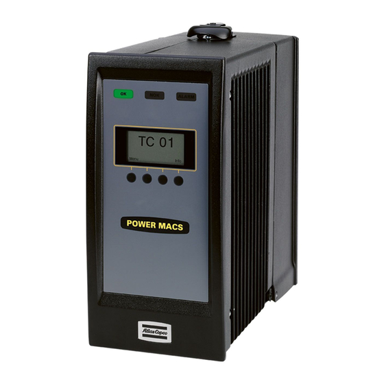
Page 30: Ptc Description
System Architecture 2.3.1.1 PTC Description All indicators are located on the front of the PTC: LEDs HMI Display Soft buttons Reset emergency stop The following LED indicators can be found on top of the PTC and are common with the LEDs found on regular TCs. - Page 31 System Architecture The Reset emergency stop button acknowledges an emergency stop for a station. Sockets on the PTC The following picture shows the input and output sockets on the PTC. Em Stop In: 12 pole Em Stop Out: 12 Dig In: 10 pole Phoenix pole Phoenix Phoenix.
-
Page 32: Tc Description
System Architecture 2.3.1.2 TC Description All indicators are located on the front of the TC. LEDs HMI Display Soft buttons The following LED indicators can be found on top of the TC and are common with the LEDs found on PTCs. - Page 33 System Architecture Sockets on the TC The following picture shows the input and output sockets on the TC. Em Stop In: 12 pole Phoenix Emergency stop in Em Stop Out: 12 pole Phoenix Emergency stop out Power Connector QST Spindle Connector 24V Input 2 pole Int Eth: RJ45 Phoenix.
-
Page 34: The Tc Hmi Menu System
System Architecture 2.3.1.3 The TC HMI Menu System The TC HMI menu system provides a flexible and intuitive interface to configure and interact with individual TCs. The TC HMI also show the status for certain operations, these include downloading of software, copying or restoring the setup from System TC to a Spindle TC and possible version conflicts detected in the system. - Page 35 System Architecture TC node. The selected default menu is remembered between TC restarts. Setup Menu The setup menu is divided into two group Basic Setup and IP Setup. Press the Select button to enter a settings group or press the Back button to return to the Default menu. Basic Setup Basic Setup Basic settings for a TC...
- Page 36 System Architecture Setup Menu – IP Setup The IP Setup is used to configure the IP addresses of the TC. PTC:s are equipped with two interfaces (internal and external) whereas regular TC:s only have one interface (internal). The following options can be set in IP Setup. Menu Description IF 1 IP Address...
- Page 37 System Architecture The events menu contains all hardware and critical system errors that have occured on the TC since the last reset. When the ALARM led is lit on a TC the error message can be found in the events menu. Show Event Ev# 5094 DC Bus Low...
-
Page 38: Version Conflict Message
System Architecture HW Serial No Spindle Hardware Serial Number HW Ver Spindle Hardware Version Serial No Spindle Serial Number Type Spindle Type 2.3.2 Version conflict message All TCs in a system, System TCs as well as Spindle TCs, must use the same TC System Software version in order to function properly. -
Page 39: Ethernet
System Architecture 2.3.4 Ethernet Communication between the Console Computer and the Tightening Controllers or between two Tightening Controllers is done with use of an Ethernet network. This runs with 100 Mbit/s and uses TCP/IP as protocol. Physical media is 10Base-TX, i.e. twisted pair, max length 100 m. By use of commercially available products it is possible to build a network with optically isolated components. -
Page 40: Peripheral Devices
System Architecture 2.3.5 Peripheral Devices The following peripheral devices can be connected to the TC or Console Computer: I/O device Printer on CC (Console Computer running ToolsTalk PowerMACS) Printer on TC ID device Communication via serial protocols ... -
Page 41: Automatic Update Of Tc, Servo And Spindle
System Architecture Automatic update of TC, Servo and Spindle 2.4.1 Automatic update Overview All TCs in a system, System TCs as well as Spindle TCs, must use the same TC System Software version in order to function properly. There are several methods to verify that this is the case for all TCs in a system. - Page 42 System Architecture Fig 1. Version conflict. Ver. Conflict Is this a Replacement TC? Press Yes if this is replacement TC. Press No if not. If the operator presses No, no software update is made and the TC panel shows the normal version conflict text.
-
Page 43: Replacement Of The System Tc And Backup Tc
System Architecture 2.4.3 Replacement of the System TC and Backup TC If the System TC detects a conflict compared with the backup TC then this situation must first be resolved before updating any other TC in the system. If the System TC detects that a backup TC with different software version exists in the system then there is no possibility to automatically detect which TC that has been replaced. -
Page 44: Automatic Update Of Servo Software
System Architecture 2.4.7 Automatic Update of Servo software When the TC is powered up a control is made to verify if the software that is running in the servo is different than the servo software stored in the TC flash memory. If it is found to be different and older that the software stored in the TC the servo is automatically updated with the newer version. -
Page 45: Automatic Update Of Spindle Software
System Architecture 2.4.8 Automatic Update of Spindle software When the TC is powered up or when a spindle is connected a control is made to verify if the software that is running in the spindle is different than the spindle software stored in the TC flash memory. If it is found to be different and older that the software stored in the TC the spindle is automatically updated with the newer version. - Page 46 System Architecture 9836 3521 01...
-
Page 47: Basic Functions
Basic Functions Basic Functions Basic Functions - Overview This part covers the basic functions, like how to handle windows and screen, security, help, etc. 9836 3521 01... -
Page 48: Windows
Basic Functions Windows This chapter gives a general presentation of the parts of ToolsTalk PowerMACS and how to operate them. Title bar On top of the screen there is a title bar. In this you can see the name and version of the application (ToolsTalk PowerMACS 7.3.0) and the name and version of the setup that you currently are working with. - Page 49 Basic Functions Commonly used Windows controls The following Windows controls are commonly referred to in this document: Textbox – Holds text that you can either enter or change Frame – Groups a number of controls that belongs together ...
- Page 50 Basic Functions Handling of windows With the menu View you can select which dockable windows you want to show and also if the toolbar and/or the status bar should be displayed. It is also possible to restore the factory default view from here and save your own view configuration.. If you have a number of windows on the screen at the same time you can get these rearranged in a structured way.
-
Page 51: Help
Basic Functions Help Function key F1 When running the ToolsTalk PowerMACS application you can get all information you need, by a press of a button. Whenever in trouble, press the function key F1 F1 activates the help system and displays information relevant the topic you are just using. This is called context sensitive help. -
Page 52: The File Menu
Basic Functions The File menu On the File menu you can find basic functions for ToolsTalk PowerMACS. The items New, Open, Close, Save, and Save as are for handling setups. Convert is used to convert an old setup to a newer version. Import and Export are also used in connection with setups. Handling setups are described in chapter: Set Up and Maintenance. - Page 53 Basic Functions An MRU list (Most Recently Used) shows previous setups that has been opened recently. Select one of these to get an instant opening of it, instead of using the Open item. Use Exit to shut down the ToolsTalk PowerMACS application. If you have modified the current setup you will be asked to save it first.
-
Page 54: How To Start Up
Basic Functions How to Start up Depending on what you want to do you start ToolsTalk PowerMACS in either Connected or Disconnected mode. If ToolsTalk PowerMACS was connected when it was last shut down it will try and reconnect to the same system upon startup. - Page 55 Basic Functions To edit a setup when Disconnected This is how you start up when you want to check or edit a setup, without connecting to a running system: 1. From the File menu select Open, or from the welcome screen, select Open an existing setup 2.
- Page 56 Basic Functions If the setup version and the TC software version differ, you will be notified and if there is a solution to the version conflict a solution will be suggested. If there is no setup loaded in ToolsTalk PowerMACS the setup will automaticly be fetched from the System TC and ToolsTalk will connect normally.
-
Page 57: Viewing
Basic Functions Viewing If you have your console PC connected to the tightening controllers (connected), you can view several items in the system. You can start View displays by use of the menu View or by pressing one of the corresponding buttons on the tool bar. - Page 58 Basic Functions The color of the items indicates the current status of the item. Color Status Green OK - Idle after OK cycle NOK – Idle after NOK cycle Orange NOKRM - Idle NOK only due to reject management after a cycle. For bolts only Yellow Running cycle Blue...
- Page 59 Basic Functions result information and background color remains. When the cycle is finished, the background color and result information is updated. In the case that the cycle is ended without any cycle data being produced (for example a sub cycle is ended in a stitching cycle using PLC station output variable DATAHOLD);...
-
Page 60: Station Views
Basic Functions 3.6.1.1 Station Views For a station, different background pictures and layouts of the station and bolt boxes can be used. The currently selected Mode number triggers which so called Station View to display. The mapping between Station Views and Mode numbers are done using the Assembly Overview Set Up form. The Station View change is triggered by a change in the Mode number. -
Page 61: System Map
Basic Functions 3.6.2 System Map The System Map gives an overview of all functional parts in the system. It can be used both as an indicator of current status for all parts, but also as a navigation tool within the system. The default location for the System Map is on the left side of ToolsTalk PowerMACS but it can be placed anywhere on the screen. - Page 62 Basic Functions When connected to a system the Station and Bolt nodes will display certain colors depending on the last status. Color Status Green OK - Idle after OK cycle NOK - Idle after NOK cycle Orange NOKRM - Idle NOK only due to reject management after a cycle. For bolts only Yellow Running cycle Blue...
- Page 63 Basic Functions Problems with equipment (hardware or devices) are indicated with a red cross over the icon. For certain devices Online info is shown below the Details window. 9836 3521 01...
-
Page 64: View Cycle Data
Basic Functions 3.6.3 View Cycle Data The Cycle Data window is used to display data from the tightening cycles. The display shows the last cycle. When new cycles are added older cycles are scrolled upwards. By use of the vertical scrollbar you can go back to earlier cycles. If the text is wider than the window, a horisontal scrollbar appears. - Page 65 Basic Functions Note! To be able to filter out the results for a specific program you must have included the bolt level result variable “Program” in the reporter named “Screen”. The result will include all cycles where at least one bolt has executed the selected program. Cycle data can be saved to file when pressing the “Get cycledata”...
-
Page 66: View Statistics
Basic Functions 3.6.4 View Statistics The Statistics window displays the statistical curves generated by the function "SPC, Statistical Process Control". First select with Station, Bolt or Spindle, Program, Variable, and Step what variable you want to study the statistics for. Only values earlier configured for SPC using the SPC set up form can be displayed. Then use the radio buttons in the upper right corner of the form to select which type of display you want. - Page 67 Basic Functions If there is a subgroup, which has possible corrupt data, you can delete it. Click in the diagram on the subgroup you want to delete. Press Delete Subgroup. This is possible only when the selection SPC and TDA is active. To the left current capability values are displayed.
-
Page 68: View Trace
Basic Functions 3.6.5 View Trace The Trace viewing window is used to present the traces of current and prior cycles. For each individual bolt's tightening cycle a trace can be generated and recorded. The maximum length of a trace is 20 seconds. If a trace is recorded for longer time than 20 seconds the oldest values will be overwritten with new samples. -
Page 69: Select Which Trace To Display
Basic Functions 3.6.5.1 Select which trace to display The controls in the top of the Trace viewing window is used to select which cycles to show traces for and which quantities to show for these cycles. You can also save and open traces from both file and the TC. Select cycle Select the bolt you are interested in by use of the Station and Bolt fields. - Page 70 Basic Functions Angle - Displays values over recorded angle. Pos. Angle - Displays values over positive angle. All angle movements are positive, i.e. the angle of the cycle is always increasing, even if the bolt was moving backwards. If Advanced view is enabled it is also possible to select the following for the second angle channel: ...
- Page 71 Basic Functions If you see a trace that is interesting in some respect you can choose to save it, either in the TC or to a disk file on your PC. To save it in the TC select the Save at TC from the Trace menu. This will cause the currently displayed trace to be tagged for save which protects it.
-
Page 72: View Of Trace Curves
Basic Functions 3.6.5.2 View of trace curves In the middle of the Trace viewing window, the curves are plotted for the selected traces and selected quantities. Zoom With the cursor you can mark a specific part of the trace to zoom in. Place the mouse pointer on the corner of the area you want to enlarge. - Page 73 Basic Functions Under the heading Selected Trace, information about the currently selected trace is displayed. When several traces are displayed (using the Select option to open traces from TC) you can use the buttons to browse through all traces. Note that two curves can be displayed for each trace. In the identity list (displayed by clicking on the button Identity>>) more information can be found for the trace.
- Page 74 Basic Functions The curves of the selected trace are highlighted compared to the other traces. This makes it easy to study a specific trace while still having several others displayed. Change the selected trace to highlight another trace. This makes it possible to browse through all traces viewing them one by one. Show Tightening limits and parameters If you select Extras | Show from the View menu the form is expanded and displays controls that are used to specify additional data to be displayed in the diagram.
- Page 75 Basic Functions The following additional data may be added to the diagram: Fail Safe limits Restrictions Checks Monitor Limits Control Parameters Step Starts and Stops To include any of the groups above in the trace check the corresponding checkbox. The respective limits or parameters are displayed only if they are relevant with respect to the trace curves currently displayed.
- Page 76 Basic Functions Show Single Step It is possible to view only one step at the time. Select Extras | Show from the View menu to bring forward the Show Single Step frame. Mark the checkbox "Show Single Step" and select which step number to show in the combobox. If quantity Angle is used on either a vertical axis or the horisontal axis, you can select to show the step angle instead of the cycle angle with the checkbox "Show Step Angle".
- Page 77 Basic Functions Show Cycle Data If you select View | Extras | Show cycle data the lower part of the window is expanded and displays more data. Press the Layout button to set up the layout of the cycle data. This will invoke the Trace Reporter, see chapter: Edit reporter.
- Page 78 Basic Functions Reference trace It is possible to save any displayed trace as a reference trace. The reference trace is stored by selecting Trace | Save as reference from the menu. There can only be one reference trace on ToolsTalk PowerMACS.
- Page 79 Basic Functions Identity of traces Select View | Extras | Identify from the menu to display a list with identity information about each trace. It is possible to change color of one or many traces at the same time. To change color of one trace, simply click on the colored button to the left in the list.
-
Page 80: Select Trace
Basic Functions 3.6.5.3 Select Trace This dialogue is invoked from the View Trace form by selecting the Trace | Select from TC menu option and is used for selecting one or several traces to display. The list shows traces stored. By use of the Show traces for… frame you can select which traces to show. In the ID field write as many characters you like. -
Page 81: View Tightening Path
Basic Functions 3.6.6 View Tightening Path The Tightening Path window displays how one or more bolts executed a cycle as a gantt chart. This layout makes it more easy to see how reject management procedures affected a cycle. To display the tightening path for a cycle, either select a cycle data by pressing the Select Cycle Data button or select one or more traces to compare. -
Page 82: View Event Log
Basic Functions 3.6.7 View Event Log In the PowerMACS system events could happen that the operator should be informed of. These can be of following types: Event type Num. Id Example General Events that do not belong to any of the specific categories below. Access Operator log-in and log-out, failed log-in attempts Power up... - Page 83 Basic Functions For each event the following information can be displayed (from left to right): If the event is observed or not (a check mark if observed) The severity of the event The date and time when the event occurred ...
- Page 84 Basic Functions Events that have been dealt with can be marked as “Observed”. Select one or more events in the list and press the Observed button. A single event can be marked by just double clicking it. An observed event shows a red check mark in the leftmost column.
-
Page 85: View I/O Signals
Basic Functions 3.6.8 View I/O signals When ToolsTalk PowerMACS is connected you can display the current status of all digital inputs and output connected to a particular TC. Use menu choice View-IO to open the IO Map form. (You can also open it from the Hardware on the System Map form. -
Page 86: Reporter
Basic Functions Reporter The reporter is a very flexible and powerful tool that is used to configure which data to display and output from a PowerMACS system. Reporters can be added, edited and removed from either the Reporter menu item or the system map. It can be seen as a function that helps you select various data from the system. -
Page 87: New Reporter
Fieldbus available using fieldbus devices available using the PowerMACS API (Application Programmer Interface) for access by other PC based computer applications via the network ToolsNet sent to a Atlas Copco ToolsNet server 9836 3521 01... - Page 88 Basic Functions You cannot create (or delete) reporters for the Screen, that is the ToolsTalk PowerMACS Cycle Data window, or the Trace, that is the cycle data display in the Trace window. On the other hand, these reporters are always available in the system. If wanted, specify an additional name of the reporter.
- Page 89 Basic Functions For most of the types you must select which device this reporter should connected to. The Device list box displays all devices, of the relevant type, existing in the system. See Add a device for how to add new devices if you need to that.
-
Page 90: Remove Reporter
Basic Functions 3.7.3 Remove reporter You can remove a reporter by menu item Reporter-Remove… Select a reporter and press Remove. You can also delete reporters by right-clicking on them in the system map and select Remove Reporter. 9836 3521 01... -
Page 91: Edit Reporter
Basic Functions 3.7.4 Edit reporter The reporter is used to specify what data to collect for a device and the layout of the data when presented on the device. All devices that should handle process data; Cycle Data, Events and Traces, must have a reporter set up for it in order for any data to be output. - Page 92 Basic Functions It is possible to adjust the preview according to a station and mode number. It is possible to hoover with the mouse above the individual fields in the address map to view the actual variable. Advanced Event settings form. ...
-
Page 93: Adding Cycle Data Variables
Basic Functions For the Screen, ToolsTalk Printer and Trace reporters you can specify which font to use. Please keep in mind that you must use a font with fix width to make the variables be printed in columns (for example when printing cycle data as table as described in chapter: Adding Cycle Data Variables. - Page 94 Basic Functions Use the check boxes in the top of the form to select variables to present in the list. If e.g. the SPC checkbox is marked the list will include SPC variables, otherwise not. It is also possible to drag & drop variables from the Dynamic Tool to the three variable list boxes. The Settings property grid shows the settings for the currently selected variable.
-
Page 95: Layout Of Cycle Data
Basic Functions Type Controls the data type of the variable when printed. Valid only when format is binary (Data/Binary selected). Takes the following values I1 - Value is formatted as a one-byte integer. Any fractional part is truncated. I2 - Data is formatted as a two-byte integer. - Page 96 Basic Functions as “blank” (all spaces) when Data is set to Printable. With Data set to Binary all undefined numerical variables are set to the value –32768 while text variables are set to an empty string, that is “”. For a description of all variables see chapter: Result variables. The parameter Type of layout controls how the printed result is formatted.
- Page 97 Basic Functions of the targeted device output area. It is possible to select where bolt data should start after the station data and how much each bolt should occupy. Within each bolt it is possible to specify the same details for step data. See Cycle Data layout example for examples of the different formats.
-
Page 98: Cycle Data Layout Example
Basic Functions Choose 1/0 (OK=1) to have an OK result, that is, OK and OKR, reported with value 1 (one) and a NOK result, that is, NOK, NOKRM, and TERMNOK, reported with value 0 (zero). Choose 0/1 ASCII (OK=0) to have the status using ASCII digits. An OK result is then reported as the digit "0"... - Page 99 Basic Functions Will produce the following print out: Station: Stn 01 Time: 011030 09:40:58 Status: OK Bolt No: 1 Bolt T: 15.1 Bolt A: 435 Status: OK Step No: 1 Peak T: 2.4 A: 125 Step No: 2 Peak T: 15.2 A: 310 Bolt No: 2 Bolt T: 2.5...
- Page 100 Basic Functions Table layout Using the same variable settings but with Type of layout set to "Table" and Header frequency to 2 gives the below printout: Station Time Status Bolt No Bolt T Bolt A Status Step No Peak T A ---------------------------------------------------------------------------------------- Stn 01 011030 09:40:58...
- Page 101 Basic Functions Standard + Table layout Using the same variable settings but with Type of layout set to "Standard + Table" and Header frequency to 2 gives the below printout: Station: Stn 01 Time: 011030 09:40:58 Status: OK Bolt No Bolt T Bolt A Status Step No Peak T A ---------------------------------------------------------- 15.1 15.1...
- Page 102 Basic Functions Fixed Positions layout Std. + TableSetting Type of layout to "Fixed Positions", the Bolts to report parameter to 5 (on the Advanced CD settings form) and the following variable settings: Station variables: Variable Width Text Station Time Status <New Line>...
-
Page 103: Reporter Preview
Basic Functions 3.7.4.4 Reporter Preview For binary reporters it is possible to preview how the generated data will be formatted. It is possible to adjust the preview according to a station and mode number. It is possible to hoover with the mouse above the individual fields in the address map to view the actual variable. -
Page 104: Advanced Event Settings
Basic Functions 3.7.4.5 Advanced Event settings Using the Advanced Event settings you can configure a filter for which events that should be sent to the device and, for reporters configured to report data in binary format, how they should be formatted. Events can be filtered on their type and their severity. - Page 105 Basic Functions Enter the text to be printed at the top of the document in the field Header on top of page/Text. For the ToolsTalk Printer you may also use the Bitmap combo box to select a bitmap to be displayed as header. Enter the text to be printed at the bottom of the document in the field Footer at bottom of page/Text.
-
Page 106: Security
Basic Functions Security PowerMACS contains a security system that prevents unauthorized access. All personnel must then be registered as users with password and access level. The access level makes it possible to allow personnel as a group or individuals to have access at these levels: ... -
Page 107: Registering Users
Basic Functions Enter the Group Name, use the controls located in the Set Access On All frame to set the access of all forms to No Access, Read or Write. It is then possible to select access level for each ToolsTalk PowerMACS window by selecting the access level in the Form Access list. -
Page 108: Login And Logout
Basic Functions The following dialog box is shown. Enter Name, Password, and select Group. Press OK to register the user. To change data for an existing user, select the name from the list and press Change…. The same dialog box appears as for a new user. Change the data and press OK. Recommendation: when security is used the group for user “Anonymous”... - Page 109 Basic Functions If no actions are made on the Console for ten minutes the system will make an automatic log out. If you have made changes to the system and you log out you will automatically be asked to enter a message in the Service Log.
-
Page 110: Printing
Basic Functions Printing Use the menu item File-Print… to print the different tables in the setup. First select the type of table you want to print in the combo labeled Table. This will display all tables of the selected type in the Source frame. Select one table by clicking on it. -
Page 111: Set Up And Maintenance
Set Up and Maintenance Set Up and Maintenance Set Up and Maintenance - Overview This part handles how to set up and maintain the system. Note! Be careful when changing data in setups. If you are connected and your system is running, a change will affect the system immediately when you press the Apply button in the current form. -
Page 112: Setups And How To Handle Them
Set Up and Maintenance Setups and How to handle them A setup is a group of data that completely describes how a system should work. The PowerMACS system uses the information in the setup to know what to do. A setup can also be called a configuration. A setup can be stored on the console computer in a file on a hard disk or on a usb memory stick. -
Page 113: Backwards Compatibility
Set Up and Maintenance If you have a setup that is too old for the software in the TC, you can Convert it to a later version (see section Backwards compatibility). If you want to copy separate tables from one setup to another you can use the Export and Import choices. -
Page 114: Plc Conversion
Set Up and Maintenance ToolsTalk is only able to emulate versions from 10.0.0 to the ToolsTalk version. Setups older than this must be converted or an older version of ToolsTalk must be used. 4.2.1.1 PLC conversion Note: When converting to a version older than 7.5.0, the PLC is not touched at all by the conversion function. -
Page 115: Compatibility Between Pm4000 Tightening And Gauging
Set Up and Maintenance b. else, variable is moved to the I/O area Then, with the remaining variables in the shared area: 2. Variables mapped by fieldbus: a. Variable is moved to the fieldbus area Drivers for the I/O area and the fieldbus areas are added automatically if not already present in the PLC program (the drivers are located in the “I/O Configuration”... -
Page 116: Set Up Of A New System
Set Up and Maintenance Set up of a new system After you have decided what physical hardware you will have in your new system you should make a setup. A setup is a file, which contains all information that is needed for the system to execute its task properly. - Page 117 Set Up and Maintenance Enter the number of bolts and spindles you want to have in the first station using the fields No. of Bolts in the Station and No. of Spindles in the Station. Enter in Default Spindle type that you have in your system. If you have more than one type select the alternative you have most of.
- Page 118 Set Up and Maintenance Here you may also change the type of the spindle and the TC corresponding to it. Press Next >>. If you specified fewer spindles than bolts in the second wizard dialog you will be displayed the following dialog: Use the combo boxes in the Spindle column to select the spindle to be used to control each of the bolts.
- Page 119 Set Up and Maintenance Enter the number of modes you want to have in the Mode table for the station (max is 50) and press Next >>. This will present the following dialog: Specify programs for the number of modes selected. You can select predefined programs located in the installation directory for ToolsTalk PowerMACS under the subdirectory Programs.
- Page 120 Set Up and Maintenance If you specified more than one station in the system the wizard will repeat the sequence above from dialog two for each station. In the next step you can add and set up devices that you will have in your system. Devices are used to get information in and out of the system, like printers, fieldbuses etc.
- Page 121 Set Up and Maintenance What data to enter depends on type of device. All parameters come up with default values. If you know what exact values you will have, you can change the values now. You can also wait and change values later, with use of the System Map.
- Page 122 Set Up and Maintenance Here you can select which predefined reporter settings that will be used for the Screen and Trace reporter. Note that it is not possible to leave these selections blank. Note that this dialog is only displayed if you have placed more than one file in the special directory for the reporter in question.
- Page 123 Set Up and Maintenance Spindle and bolt setup‟s, one for each item specified. Specified programs. A mode table for each station specifying the programs you have selected. SPC configured for measuring the final torque and angle for each of the bolts. ...
-
Page 124: System Map
Set Up and Maintenance System Map The System Map by default docked on the left side of ToolsTalk PowerMACS main window is the place to check and alter the system configuration (setup). You can expand or collapse the tree structure by clicking on an item or clicking in the small squares with + and -. -
Page 125: Logical View
Set Up and Maintenance To add or remove items simply right-click in the system map. However, even though it is possible to add/remove logical items, such as stations and bolts, displayed on the System tab it is recommended that you use the File-New Wizard (see chapter: Creating a new system using the Set Up Wizard) when doing major structural changes to your system. -
Page 126: System Node
Set Up and Maintenance 4.4.1.1 System node Select the System node by clicking on it using the mouse. This will make all properties of the System to be displayed to in the Details window. Use the Name field to change the name of the System. It identifies the system, and setup, and may be up to 20 characters long. - Page 127 Set Up and Maintenance See chapter: Station Set Up for a description of the parameters. 9836 3521 01...
-
Page 128: Bolt Node
Set Up and Maintenance 4.4.1.3 Bolt node Select a Bolt node to display the most common properties of the Bolt. Use the Name field to change the name of the Bolt. This name will identify the Bolt in cycle data reports, etc. -
Page 129: Reporters Node
Set Up and Maintenance A program can be opened in The Tightening Program form by double clicking it or right clicking and selecting Open Program, to remove a program right click and select Remove Program. 4.4.1.5 Reporters node Clicking on the Reporters node will in fold/unfold a list of all reporters defined in the system. A reporter can be opened in the Reporter form by double clicking a reporter or right clicking and select Open Reporter. -
Page 130: Hardware Node
Set Up and Maintenance 4.4.2 Hardware node The Hardware node of the System Map contains all hardware in the system, this node is the primary resource when configuring or monitoring the hardware configuration. The tree level below Hardware contains a list of all TCs in the system. 9836 3521 01... -
Page 131: Tc Node
Set Up and Maintenance 4.4.2.1 TC node The TC node represent a TC in the system. For each TC it is possible to change name and select which monitoring buffer to use for the TC HMI:s Torque and Angle values. By default the internal and external Ethernet ports are configured from the TC front panel. - Page 132 Set Up and Maintenance device and then right click and select Add Device. This will bring up the Add Unit form in which you select the type of device to add. Most devices that should handle result data require a Reporter to function properly. The Reporter controls what data that is reported over the device, and how it is formatted.
-
Page 133: Spindle Node
Set Up and Maintenance Note! Upgrading the spindle software might require re-programming of spindle parameters and motortuning. 4.4.2.2 Spindle node Select a Spindle node to display the most common properties of the Spindle. Use the Name field to change the name of the Spindle. This name will identify the Spindle in cycle data reports, etc. -
Page 134: Other Device Nodes
Set Up and Maintenance 4.4.2.3 Other device nodes Selecting any node of any other device type will display the parameters of the selected device type. For most devices all parameters are displayed in the Details window. Devices that have many parameters make use of a specific form to access these. For such devices an Open…... -
Page 135: Station Set Up
Set Up and Maintenance Station Set Up Select a Station node object on the System tab and make sure the Details window is visible to display the parameters available for a Station. The name entered in the Name field defines the name of the Station. It will identify the Station in cycle data reports, etc. - Page 136 Set Up and Maintenance Note! Allowing hold torque during RM dramatically increases the risk of burning the motors! Report Cycle Data at emerg. stop controls whether or not cycle data is reported for a cycle interrupted by an emergency stop (caused by setting the PLC variables EMERGSTOP or MACHINESTOP, or if the Station loses communication with one or more of its TCs).
-
Page 137: Advanced Station Settings
Set Up and Maintenance 4.5.1 Advanced Station Settings The Advanced Station Settings form is invoked by pressing the Open... button in the System Map when the selected node is a Station, alternatively it is possible to right click on a station and select Advanced Station Settings from the popup menu. -
Page 138: Work Piece Identifier
Set Up and Maintenance 4.5.1.1 Work piece identifier The Work piece identifier (Wp ID) function makes it possible add an identifier string read from an ID device, for example a barcode scanner, to the result data as the result variable "Wp ID" (see Station level result variables). - Page 139 Set Up and Maintenance The Multiple identifier function can be monitored and controlled from the PowerMACS PLC using its Multiple identifier variables. Multiple identifiers are defined in two steps using Identifier types and Result variables. Identifier types An Identifier type is a string supplied by an identifier Source, that is, a device that supplies the identifier data, and fulfills an optional match condition.
- Page 140 Set Up and Maintenance For Identifier Type 1 up to twenty significant strings can be specified using a Conversion table. Aside from that each of these strings are tested, one by one until a match is found, the same matching rules applies. With the Conversion table it is also possible to have the matching identifier string automatically converted to a numerical value available in the PLC as input IDTYPE_1_CODE (see PLC chapter: Multiple identifier variables).
- Page 141 Set Up and Maintenance Note Using ambiguous Types makes the operator, or overriding control system, responsible for supplying the identifiers in the expected order. The values of the Identifier Types included in the Work Order are not available to the Station as long as the Work Order is active.
-
Page 142: Plc Event Handling
Set Up and Maintenance 4.5.1.3 PLC Event handling The Advanced Station Settings form also enables you to configure which type of Events that should be possible to mark as observed from the PowerMACS PLC using the outputs named ACKxxxEVENT. Only the types checked in the Event types possible to mark as observed from the PLC frame will be possible to acknowledge from the PLC. - Page 143 Set Up and Maintenance This string is then tested against the Significant strings one by one, starting from the top, until a match is found. If a match is found, and a Code is specified for the matching string, its value is returned. If there is no match, or the Code column is empty, the result is set to NOT_DEFINED (-32768).
- Page 144 Set Up and Maintenance Set of characters Matches any one of the characters enclosed within the []. Example: [abc] matches any single occurrence of the characters 'a' 'b' or 'c'. <OptRangeCheck> Range check start Marks the start of a range check (see Example A Conversion table with Significant positions set to 1-10, 24 and the following Significant string / Code pairs:...
-
Page 145: Spindle Set Up
Set Up and Maintenance Spindle Set Up There are many parameters that control the running of a spindle. During set up these parameters are given default values. In some cases this is not enough. Therefore it is possible to change all parameters with the Spindle Set Up form invoked by selecting the Spindle item in the Set Up menu or by double clicking the spindle in the System Map. -
Page 146: Calibration Page
Set Up and Maintenance To use a conversion box for QMR/QMX spindles, see appendix Configuration of the Conversion Box. The parameter Service interval is used to define the service interval, in number of cycles. To disable the time for service event check the Disable time for service event checkbox. 4.6.2 Calibration page The Calibration page is used to calibrate a spindle. -
Page 147: Application Page
Set Up and Maintenance The T/C Correction Factor is used to calibrate the current measured as torque values. 4.6.3 Application page The Application page contains application specific parameters, they are stored only in the setup and not on the spindle. Use the Direction field to select the basic direction for the spindle, normally Forward (clockwise). -
Page 148: Application External Equipment
Set Up and Maintenance Specify in Dig output for Gear Shift the digital output that is connected to the spindles gearshift unit. This can be controlled using the GS - Run Gear Shift step. Enter as <TC no.>.<channel>, e.g. 1.4. Leave blank if you do not have any output for this. -
Page 149: Angle Channels Page
Set Up and Maintenance 4.6.4 Angle Channels page The Angle Channels page contain information about the equipped angle channels. It is also possible to configure the double transducer check here. This page shows basic properties for each equipped angle channel, it is possible to Disable the secondary Angle channel (if equipped). - Page 150 Set Up and Maintenance It is possible to select if the limits for the test should be read from the spindle (default provided) or if you want to specify your own limits. The Spindle defined limits are only displayed when ToolsTalk PowerMACS is connected to a system.
-
Page 151: Torque Channels Page
Set Up and Maintenance 4.6.5 Torque Channels page The Torque Channels page contain information about the equipped torque channels. It is also possible to configure the double transducer check here. This page also show information about the current channel. This page shows basic properties for each equipped torque channel (including the Current channel), it is possible to disable any channel here by unchecking the Enabled checkbox. - Page 152 Set Up and Maintenance It is possible to select if the limits for the test should be read from the spindle (default provided) or if you want to specify your own limits. The Spindle defined limits are only displayed when ToolsTalk PowerMACS is connected to a system.
-
Page 153: Diagnostic Page
Set Up and Maintenance 4.6.6 Diagnostic page The parameters located on the Diagnostic page specifies the limits of the zero offset tests in the D - Diagnostic Step. Only the equipped channels are visible. It is also possible to specify if a cycle should continue to run after a failed flying zero offset test. -
Page 154: Dynamic Zero Offset And Angle Count
Set Up and Maintenance 4.6.6.2 Dynamic Zero Offset and Angle Count Dynamic zero offset is measured as the average torque while the spindle first runs the specified Target angle degrees in forward direction and then in the reverse direction. If an Angle count test is specified the motor will run exactly as when performing a Dynamic zero offset test. -
Page 155: Order Of Execution
Set Up and Maintenance 4.6.6.4 Order of execution The below text describes the sequence of actions that can occur: IF (Static Zero Offset test) THEN Measure the Static Zero Offset; Save as Zero Offset compensation value if within limits; ENDIF IF (Dynamic Zero Offset test OR Angle test) THEN First run in the forward direction and then in the backward direction;... -
Page 156: Motortune Page
Set Up and Maintenance 4.6.7 Motortune page If you have a service enabled ToolsTalk PowerMACS it is possible to Motortune a spindle. Press Start Motortune to begin the motortune operation, note that the spindle will run at a very high speed so it is absolutely critical it is running free. -
Page 157: Automatic Transducer Protections
Set Up and Maintenance 4.6.8 Automatic transducer protections To protect the transducer from overload a number of non-configurable restrictions are continuously executed. The errors produced by these tests are always considered Fatal. Transducer overload protection (Spindle Protection) This test supervises that the torque measured on the monitoring channel does not exceed the maximum allowed torque for the spindle. -
Page 158: I/O
Set Up and Maintenance The I/O form is invoked using menu item Setup – I/O…. or by double clicking an I/O device in the System Map. An I/O device is used to communicate with hardware modules for digital input and output signals. This can be connected to all PTCs that run a station. - Page 159 Set Up and Maintenance Press Add to add a new node. A new node is added with header but with no inputs or outputs. Press Remove to remove the last node. Press Apply to make to the change immediately without leaving the form.
- Page 160 Set Up and Maintenance When a node is initially added it is set up with a default configuration. Node PLC input signal PLC output signal Name of signal 600..663, if there is one Name of signal 800..863, if there is one Name of signal 664-727, if there is one Name of signal 864-827, if there is one Name of signal 728..791, if there is one...
-
Page 161: Local I/O
Set Up and Maintenance 4.7.1 Local I/O Local I/O is visible as the first node of the I/O device. In order to map the local I/O, add an I/O device to the setup and open the I/O form The Local I/O is mapped by selecting PLC signals in the comboboxes in the form, like for the other I/O nodes. -
Page 162: Id Device Set Up
Set Up and Maintenance ID device Set Up The ID device form is invoked using menu item Setup – ID device…. or by pressing the Open... button displayed in the Details window when the selected node in the System Map is an ID device. Select the ID device to view or configure using the ID device combo box. -
Page 163: Assembly Overview Set Up
Set Up and Maintenance Assembly Overview Set Up The Assembly Overview displays the current status of the system, its stations and bolts. Which data to display in the different boxes, and their layout, are controlled by the Assembly Overview Set Up form. It is invoked using the Set Up - Assembly Overview…... - Page 164 Set Up and Maintenance The Assembly Overview Set Up form Use the System Background Picture combo to select the JPG file to display as System View background. To include your own JPG files you must copy the files to the directory Bmp located in the directory you installed the ToolsTalk PowerMACS application in.
- Page 165 Set Up and Maintenance The above listed configurations are common for a given station regardless of which mode the station is running (see The Mode Table form for a description of modes) . However, there are a number of aspects that can be displayed differently depending on the currently selected mode: These are defined as a so called Station View.
- Page 166 Set Up and Maintenance The Assembly Overview form in Set Up mode This form is used to define the position and size of the different station and bolt boxes. The layout is modified directly in the displayed picture by using the mouse. To change the positions of a box move the mouse pointer to the upper left corner of the box.
-
Page 167: Plc Parameters Set Up
Set Up and Maintenance 4.10 PLC Parameters Set Up This form is invoked using the menu item Set Up - PLC Parameters. The PLC Parameters Set Up form is used to define parameters that are available from inside the PowerMACS PLC (see PLC - Overview). Defining parameters for the PLC here is an alternative to defining them as a part of the PLC application directly (using the Multiprog editor). -
Page 168: Sram
Set Up and Maintenance 4.11 SRAM This form is invoked using the menu item Set Up - SRAM. Use this form to set up the configuration of the TC:s SRAM. Change the size used for cycle data storage by dragging the slider Cycle data percentage. The digits shown to the right of each slider is a guess of the minimum amount that can be stored given the selected settings. -
Page 169: Options
Set Up and Maintenance 4.12 Options In the Options choice of the Set Up menu you can set up your main preferences. Choose Language for presentation on screen. Change will take place when windows are closed and reopened. Note 1: All texts displayed by ToolsTalk PowerMACS are defined in a so-called Language file. To add support for a new language you just have to copy a file supporting the language in the same directory as your ToolsTalk PowerMACS is installed in. - Page 170 Set Up and Maintenance Use Time Server to select from where the clock on the target system will be synchronized. Normally the only option is ToolsTalk PowerMACS but if the system has an Ethernet Protocols device mounted on the System TC then the following alternatives are available as well: ...
-
Page 171: Set Customer Step Names
Set Up and Maintenance Note 4: The parameters Language and Automatically restore ToolsTalk-TC com. when broken are not part of the setup. Their values are only stored on the PC from which the parameters are altered. However, since the values are stored in the PC's registry they are remembered between different sessions, also if using different setups. -
Page 172: Set Customer Error Codes
Set Up and Maintenance 4.12.2 Set Customer error codes Click on Set Customer error codes… to display a window where customer specific error codes can be defined and edited: The customer error code is a four (4) character string that can be included in the bolt level result data. Five different series with customer error codes can be used. - Page 173 Set Up and Maintenance Customer error codes can also be specified for the two cases when the cycle ends without any error bit set, that is, when the cycle ends with status OK, OKR or NOKRM (see chapter: Result variables - Statuses for a description of statuses).
-
Page 174: Setup Problems
Set Up and Maintenance 4.13 Setup Problems The Setup Problems function performs a number of tests on your setup. It will test all combinations of programs against the bolt/spindles that you have setup using The Mode Table form. All target values will be tested with respect to max values defined for the spindles used. -
Page 175: Table Export And Import
Set Up and Maintenance 4.14 Table Export and Import A setup is a group of data that completely describes a PowerMACS system, how it looks and how it should work. It can be handled and reused as a complete unit as described in the chapter: “Setups and How to handle them”. - Page 176 Set Up and Maintenance Use the Destination frame to specify to which file the table should be stored. Finally press the Export >> button. Repeat this for all tables you want to export. Use the File - Export menu item to display the Import Table form. First select the type of table to import using the Table combo.
-
Page 177: Table Copy
Set Up and Maintenance 4.15 Table Copy This form is opened using the menu item Edit - Multi Copy. It enables easy copying of a table instance to one or more other instances of the same type. Use the Table combo box to select which type of table to copy. Depending on type of table you can then in the Source frame specify which table you want to copy. -
Page 178: Handling Of The Setup In The Target System
Set Up and Maintenance 4.16 Handling of the setup in the target system The setup consists of all the configuration objects stored in the database along with the PLC program including the PLC source code. When downloaded to target system this setup data is stored on the System TC. It is from this TC all other TCs in the system access the data they need. - Page 179 Set Up and Maintenance During a cold start of the System TC checks the status of its own local database and the backup copy stored on TC 2. Depending of their respective status the following cases can arise during system start-up: Status of Status of the Case...
-
Page 180: Replacement Of Tcs
Set Up and Maintenance 4.16.2 Replacement of TCs As described in the table in chapter: Backup of the setup there is only one case where it is not clear to the system which setup to use. That is when both the System TC and TC 2 have valid but different setups stored. -
Page 181: Maintenance
Set Up and Maintenance 4.17 Maintenance The Maintenance menu contains functions for maintenance, like checking the status of the system: Test Bolts… opens a form from where you can run test passes for one or more bolts of a station. This is an alternative to the PowerMACS PLC when it comes to start tightening cycles. - Page 182 Set Up and Maintenance Clear data… is used for clearing data stored in the non volatile RAM of the TCs. Chose Compare programs The Compare programs form, which is invoked using menu item Maintenance – Compare programs…, is used to display the differences between the programs in two different setups. Select two setups to compare, then press the Compare button.
- Page 183 Set Up and Maintenance By default, only the changes are displayed. To display the complete program, uncheck the checkbox Show changes only. Press the Print button to print the result and/or Save As… to save the result as a RTF file on disk. Note! The algorithm used for comparing the two programs strives to find the smallest edit script needed to change the program on disk to become equal to the program currently loaded.
-
Page 184: Select Target System
Set Up and Maintenance 4.17.1 Select Target System Selecting the Maintenance - Select Target System menu item or Select Target System... from the Connect toolbar drop down menu opens this form that is used to select which target system ToolsTalk PowerMACS should connect to when going online. - Page 185 Set Up and Maintenance All System TCs found during scan are compared to the contents of the currently selected Network Configuration file. Depending on the differences the rows in the list is marked with a color. – The TC in the list was not found on the net. When a network configuration Not scanned (Blue) file is opened, all rows are marked blue.
-
Page 186: Test Bolts
Set Up and Maintenance 4.17.2 Test Bolts The Test Bolt function gives you an alternative way to the execution of a tightening cycle, running all or only one selected bolt for a station. First chose which station to test using the Station combo box in the toolbar. Depending on the status of the selected station the Test Bolt form may be disabled. - Page 187 Set Up and Maintenance Should the Test Bolt form be closed, or ToolsTalk PowerMACS be disconnected from the TCs, while a cycle is executing then the cycle is terminated using Machine stop. Note! When running a station from the Test Bolt form the PowerMACS PLC outputs MODE and BOLTCONTROL are overridden.
- Page 188 Set Up and Maintenance Here you can specify how many cycles you want to run, or for how long. If you want to run more than one cycle you will probably need to specify a program to use for loosening (Program 2). How to create a new program is described in chapter: Create a new Tightening Program.
- Page 189 Set Up and Maintenance Mode Table mode In Mode Table mode you run the bolts by ordering the station to run a particular mode. This means that which bolts that will run and which programs they will execute is decided by the current Mode Table (see The Mode Table form).
-
Page 190: Calibration Procedures In Powermacs
Set Up and Maintenance 4.17.3 Calibration procedures in PowerMACS 4.17.3.1 General It is strongly recommended to perform a calibration of the spindles after the system has been installed at the production site. It is also recommended to make a new calibration periodically (for example one time a year, every 6 months etc.) and this is normally specified in the customer quality control system. - Page 191 Set Up and Maintenance Single Run When you use this function, you will automatically get some statistics directly on the screen. Do the following: Select a station. Select a spindle. Select a speed. The same speed as you have in the final tightening step in the normally used program is a good choice.
-
Page 192: Torque
4.17.3.2 Torque All Atlas Copco torque transducers are factory calibrated to a sensitivity within +/-0.3% of the nominal torque. Due to component tolerances in the TC electronics a fine tune of the torque sensor is recommended. Exchange of a torque transducer to an identical unit does not require a new calibration, but for quality control reasons it is anyway normally done. - Page 193 Set Up and Maintenance Single torque transducer If you are using the “Single run” option, run a program with a “Diagnostic” step with spindle functional test enabled to get a new zero offset reading and compensation from the spindle. ...
-
Page 194: Angle
(see “wind up” below) as all this is hardware. The most reliable results are achieved with an inline Torque/Angle transducer and a Torque/Angle amplifier with trace capability, for example an Atlas Copco IRTT transducer with ACTA. There are two methods of checking the angle measuring. -
Page 195: Wind Up Coefficient
Set Up and Maintenance 4.17.3.4 Wind Up Coefficient There is a spindle parameter, named Wind Up Coefficient (see Spindle Set Up, Calibration page), which is used to compensate for the torsion in the mechanical parts (gears and shafts) between the electric motor shaft and the square drive. - Page 196 Set Up and Maintenance 3.5 Deg 45 Nm Program the new Wind Up Coefficient in the spindle interface and Apply. Run a new tightening and look at the trace again. Now, the curve should look something like the example shown below.
-
Page 197: Current (Torque)
Set Up and Maintenance 4.17.3.5 Current (torque) The step types TC - Run until Torque with Current Control, DT - Run until Dyna-TorkTM, DT2 - Run until Dyna-TorkTM, method 2, and DT3 - Run until Dyna-TorkTM, method 3 are uses the servo current measurement for step control. -
Page 198: Event Statistics
Set Up and Maintenance 4.17.4 Event Statistics The Event Statistics form, invoked using the menu choice Maintenance - Event Statistics…, can give you a good view on which events that are most frequent. It displays a so-called Pareto diagram in which the most frequent event type is displayed to the far left. In the diagram you can see both the percentage and the number of times each event has occurred. -
Page 199: Service Log
Set Up and Maintenance 4.17.5 Service Log The Service Log is a useful tool to keep track of changes made to a system. It is invoked from the menu Maintenance - Service Log… Basically it functions as a notepad where you easily can write small notes. Use it to describe all the changes you do to the system, and perhaps more importantly, why you have done them. -
Page 200: Replace Id String
Set Up and Maintenance 4.17.6 Replace ID String Using the Replace ID String form, opened from the menu Maintenance - Replace ID String…, you can manually enter an ID string instead of actually input it using one of the ID-device devices in your system. This is useful if when a barcode label is damaged, or when the ID device for some reason is not working. -
Page 201: Configure Target System
Selecting the Maintenance - Configure Target System menu item opens the Configure Target System form. This form is used for configuration of your PowerMACS 4000 TCs. This includes functions for downloading new software and changing their IP-address data. Press the Scan button to bring up a list of all available Tightening Controllers connected to the same physically network as ToolsTalk PowerMACS. -
Page 202: Advanced Mode
Set Up and Maintenance Download Ok – Means that the boot loader has successfully downloaded System Software to the TC. The TC must be restarted for the new software to take effect. Download failed or Download Aborted – Means that the boot loader failed to download System Software to the TC. -
Page 203: Restart Of Tc's After Download
Set Up and Maintenance 4.17.7.2 Restart of TC’s after download When all selected TC‟s have successfully downloaded new software, the user is promted to restart them. 4.17.7.3 Information fields The information fields are divided into groups Default, Spindle SW, Spindle Info, Servo, TC SW, TC HW, and IP Addresses. - Page 204 Set Up and Maintenance Spindle HW Sp. model Sp. serial no Sp. art. no Sp. HW serial no Sp. HW ver Sp. cycles Sp. cycles since service Sp. cycles to next service Servo ...
- Page 205 Set Up and Maintenance TC art. no PCB serial no PCB type PCB ver. Fieldbus If the TC is configured as a System TC. The System TC is the TC that controls all other TCs included in a PowerMACS system.
- Page 206 Set Up and Maintenance Change Net Data form. Press the Download button to prepare download of System Software using the form Prepare TC for download of software. To enable the telnet interface on a TC klick the Telnet menu item. Note The Telnet server is only used for advanced debugging purposes and should normally be switched off during normal operations.
-
Page 207: Prepare Tc For Download Of Software
Set Up and Maintenance 4.17.7.4 Prepare TC for download of software This form is used to select which software file to load to TCs selected for the operation. To reduce the risk for non-repairable errors caused by failures during software download the application is divided in two parts, the boot loader and the application. - Page 208 Set Up and Maintenance 2. Click OK to prepare the selected TCs to download the specified file. This will cause a "Prepare TC for download" command to be sent to the TCs. The success or failure of this command is displayed in the Configure Target System dialog.
-
Page 209: Change Net Data
Set Up and Maintenance 4.17.7.5 Change Net Data This form is used for changing the network settings for one or more TCs. Enter the new values in the field displayed The Main Net Address determines the first three numbers in the IP address for the TC. The TC number set on on the TC display gives the last number of the address. -
Page 210: Clear Data
Set Up and Maintenance 4.17.8 Clear data The Clear data form is invoked using the menu item Maintenance – Clear data…. The Clear Data form is accessible only when on-line and is used to clear process data stored in the non volatile memory on the TCs. -
Page 211: Compare Programs
Set Up and Maintenance 4.17.9 Compare programs The Compare programs form, which is invoked using menu item Maintenance – Compare programs…, is used to display the differences between the programs in two different setups. Select two setups to compare, then press the Compare button. When the two setup files are read all programs that have the same name in the respective setups are compared to each other. - Page 212 Set Up and Maintenance By default, only the changes are displayed. To display the complete program, uncheck the checkbox Show changes only. Press the Print button to print the result and/or Save As… to save the result as a RTF file on disk. Note! The algorithm used for comparing the two programs strives to find the smallest edit script needed to change the program on disk to become equal to the program currently loaded.
-
Page 213: Check For System Conflicts
Set Up and Maintenance 4.17.10 Check for System Conflicts The Check for System Conflicts form, normally invoked using menu item Maintenance – Check for System Conflicts…, is a tool for checking if the system contains conflicting TCs and/or TCs with different versions of the TC System Software. -
Page 214: Tc Crash Log
Normally you should not run in to situations where this tool is needed but if you do the data it retrieves can be of great help to Atlas Copco when analyzing the fault. Use the Fetch log from TC combo box to select which TC to upload data from. Choosing the All alternative will make all TCs be polled for data. -
Page 215: Plc
PLC - Overview In every PowerMACS station there is a PLC (Programmable Logical Controller), called PowerMACS PLC. This is programmed in a standardized, graphical, way according to the standard IEC 61131-3. This part describes how to set up and use the PLC. A general description of the PLCs role in, and interface to, the PowerMACS system is given in the next two chapters: General and System Globals. -
Page 216: General
General PowerMACS PLC has a primary assignment to interface customer control system and peripheral devices through different communication interfaces. It is used as ”glue” between various functions within the system, as for example: Start of tightening from digital inputs ... - Page 217 The Cycle Data interface makes it possible to read data produced as cycle data result. See the description of PLC in chapter: Peripheral Devices, for how to enable this function. 9836 3521 01...
-
Page 218: System Globals
System Globals The System Globals is the interface between the PLC and the tightening controller part of the system. By setting global outputs from the PLC you can order ID devices to be read, start a tightening cycle and so on. - Page 219 Variable Type CD_OVERRUN_W1 BOOL This input is set True when there is room for less than 10 more cycle data in the cycle data queue for any device. If set, it is automatically reset when all devices have space for at least 10 more data, that is when the failing device has read its queue CD_OVERRUN_W2 BOOL...
- Page 220 Variable Type CONS_IN_1 BOOL Input connected to the ToolsTalk PowerMACS form PLC Console. CONS_IN_2 BOOL Input connected to the ToolsTalk PowerMACS form PLC Console. CONS_IN_3 BOOL Input connected to the ToolsTalk PowerMACS form PLC Console. CONS_IN_4 STRING(40) Input connected to the ToolsTalk PowerMACS form PLC Console. CONS_IN_5 STRING(40) Input connected to the ToolsTalk PowerMACS form PLC Console.
- Page 221 Variable Type SPINDLECONTROL ARRAY[1..50] This output control which spindles to run when the station is started. OF BYTE Takes one of the following values: 0: Connect normally. The bolts connected to the spindle will run the tightening program specified in the mode table when station is started.
- Page 222 Variable Type PLC_DI_1..10 BOOL These signals can be set at specific times directly from the tightening programs, e.g. at step start or zone end. See Ramps & Other – Signals at step start and end (only available for Gauging) 9836 3521 01...
- Page 223 Outputs used for controlling the station: Variable Type MODE Set to number of mode to use in next cycle. Sampled on the positive edge of START. RESET BOOL Reset servo errors on a positive edge. Should only be set True if the station is idle.
- Page 224 Variable Type GENOUT_1 ... General output. Can be used for selection of double encoders or GENOUT_5 change of spindle direction. See chapter: Spindle Set Up. FREESTRING STRING(40) The value of this output can be included in the cycle data result as the station level result variable "Free Str".
-
Page 225: Loosening Cycles
Variable Type ACKSPCEVENT BOOL Set this output True to mark all events of type "SPC" as observed (see View Event Log). CONS_OUT_1 ... STRING(40) Outputs connected to the ToolsTalk PowerMACS form PLC CONS_OUT_5 Console. RESETSTATUS BOOL Set this output True to reset the status of the station, and all bolts of the station, in both the PLC and ToolsTalk PowerMACS. - Page 226 The loosening functionality is only activated if the tightening cycle is started from the PLC, it does not affect cycles started from TESTBOLT, ACTA or GM-DEVICNET devices. The standard PLC program that is generated by the wizard contains signals, outputs and functions to support this.
- Page 227 The following shared memory variable also reflects the configuration and status of the station and system. Even though they are defined as shared memory variables, which mean that the PLC application can write to them, they should be used as inputs only. Variable Type NO_OF_BOLTS...
- Page 228 Variable Type STATIONSTATUS_EXT STATION_STATUS_ This variable indicates the station status of the last EXT_TYPE tightening. It is a structure containing the following BOOL flags: OK True if result is OK or OK after RM (OKR). OKRM True if result is OK after RM. ...
- Page 229 Variable Type SYS_DEVTYPE_ERR DEVTYPE_ERR_ This variable indicates erroneous devices in the system TYPE per device type category. The DEVTYPE_ERR_TYPE is a structure containing a BOOL flag for each type of device, plus TC and Servo, that can be included in PowerMACS system: ...
- Page 230 Variable Type DEVICE_STATUS DEVICE_STATUS_ This variable indicates status of devices. The variable is an array of BYTE where each element represents the device with the number equal to the array index number. That is, DEVICE_STATUS[10] shows the status of the device with device number 10.
-
Page 231: Bolt Variables
5.3.2 Bolt variables The following inputs can be used to monitor the status of each individual bolt: Variable Type COMPERRORS ARRAY[1..50] Reports the most commonly reported bolt errors for each of the OF BYTE bolts. The respective bits have the following meaning (bit 0 is the least significant): ... - Page 232 Use the below output signals to control the behavior of the bolts: Variable Type BOLTCONTROL ARRAY[1..50] This output controls which bolts to run when the station is started. OF BYTE Takes one of the following values: 0: Connect normally. The bolt will run the tightening program specified in the mode table when station is started.
- Page 233 The following shared memory variable also reflects the state and status of the bolts. Even though they are defined as shared memory variables, which mean that the PLC application can write to them, they should be used as inputs only. Variable Type BOLTGROUPS...
- Page 234 Variable Type BOLTSTATE BOLT_STATE_ARR This variable is an array of 50 elements of type BOLT_STATE_TYPE. Each element indicates the current state of a bolt. The BOLT_STATE_TYPE is a structure containing the following BOOL flags: DONOTRUN True if the bolt is ordered not to run, either using the PLC output BOLTCONTROL or the ToolsTalk PowerMACS "Mode Table"...
-
Page 235: Id Device Variables
5.3.3 ID device variables The following input and outputs can be used to control and monitor the Stations Work piece identifier function. See chapter: Advanced Station Settings for this is set up. Inputs: Variable Type IDSTATUS Status for ID device read or write operation: ... -
Page 236: Multiple Identifier Variables
Example: The below code issues an IDREAD order when the signal "Customer_Start_Signal" is set True, waits for the string to be returned, and then starts the tightening cycle. 5.3.4 Multiple identifier variables The following input and outputs can be used to control and monitor the Stations Multiple identifiers function. - Page 237 Outputs: Variable Type IDTYPE_1_RD ... BOOL Set to True to order a read of the ID device configured as Source for IDTYPE_6_RD the respective Identifier Type. Note! Issuing a read order using one of these outputs does not automatically lead to that the returned string is assigned the corresponding Identifier Type.
-
Page 238: Gm Devicenet Variables
5.3.5 GM DeviceNet variables The following shared memory variables serve as the discrete interface to the GM DeviceNet device. For a more detailed description of the GM DeviceNet device see chapter: GM DeviceNet. Even though the following variables are defined as shared memory type, which mean that the PLC application can read and write to them, they should be used as outputs only (seen from the PLC): Variable Type... - Page 239 Even though the following variables are defined as shared memory type they should be used as inputs only (seen from the PLC): Variable Type GM_OUT GM_OUTPUT_TYPE This variable represent the discrete outputs from the GM DeviceNet device. GM_OUTPUT_TYPE is a structure containing the following BOOL flags: ...
-
Page 240: Dc Plus Variables
5.3.6 DC PLUS variables The following variables are used for control of a DC PLUS Ethernet device. For a more detailed description of the DC PLUS Ethernet device see chapter: DC PLUS. Inputs (seen from the PLC): Variable Type PLUS_CONNECTED BOOL TRUE if a connection to the PLUS server is established. - Page 241 Variable Type PLUS_CHECKCOM_NOK BOOL TRUE if the latest test of the communication, started from the PowerMACS PLC with PLUS_CHECKCOM, failed. Outputs seen from the PLC: Variable Type On a positive edge a test telegram “TSTS” is sent to the PLUS PLUS_CHECKCOM BOOL server.
- Page 242 Variable Type PLUS_DOKUENABLE BOOL Set high to send Cycle data to PLUS. If the signal is high when a new Cycle data is produced it will be sent immediately to PLUS. If the signal is low when a new Cycle data is produced the new data will be stored in the Cycle data queue for the PLUS device.
-
Page 243: Globals
5.3.7 Globals These variables are used to transfer information from one station PLC to another station PLC. All stations can reach these global variables. Variable Type SYSTEMGLOBAL For communication between PLCs on different stations. The variables are declared as a shared memory and can therefore both be read and written to both by the PowerMACS System and the PowerMACS PLC. -
Page 244: Bolt Specific Commands
5.3.8 Bolt specific commands The bolt specific commands enables extended control of individual bolts using the following input and outputs variables. Outputs: Variable Type BOLTCTRL2_CMD The command to execute on the bolts selected using BOLTCTRL2_BOLTSEL. See table below for supported command codes. - Page 245 Inputs: Variable Type BOLTCTRL2_STS Overall execution status of the BOLTCTRL2 command: 0: Idle and OK. Command completed OK for all bolts selected. 1: Idle and NOK. Command failed for at least one of the bolts selected. Check BOLTCTRL2_BOLTRES for status of the individual bolts.
- Page 246 BOLTCTRL2_BOLTSEL[3] = 0 BOLTCTRL2_BOLTSEL[4] = 0 Then order the station to remove the last result stored for the selected bolts by changing BOLTCTRL2_CMD from 0 to 1. Wait for BOLTCTRL2_STS to become 0 (idle OK). This indicates that the station has completed the drop command.
-
Page 247: Device Commands
5.3.9 Device commands Using the device command input and outputs it is possible to control individual devices directly from the PLC. Outputs: Variable Type DEVCMD_CMD The command to send to the device pointed out by DEVCMD_DEVNAME. See table below for supported commands. - Page 248 Inputs: Variable Type DEVCMD_STS Overall execution status of the DEVCMD command: 0: Idle and OK. Command completed OK. 1: Idle and NOK. Command failed. 2: Busy executing the command. Note! The operation is not complete until this signal is 0 (or 1 if it fails).
-
Page 249: Programming The Plc
Programming the PLC To edit the PLC program select the item Program from the PLC menu. For every PowerMACS setup there is a PLC project. This project is created by the setup wizard, see Creating a new system using the Set Up Wizard, and is stored on disk together with the PowerMACS setup file. - Page 250 To execute a program the Resource uses one or more tasks. A task controls the time scheduling of a program. Tasks are typically cyclic which means that they are executed periodically with a given time interval. The Setup Wizard creates one task named T10MS, which is executed every 100th millisecond, for each of the resources.
- Page 251 Fieldbus_Variables: - This group contains the fieldbus mapping. See chapter: Fieldbus Interface. Digital_In_Out: - This group contains variables only for digital I/O. Unlike the Shared_Variables group, these signals are not shared with fieldbus. The programming of the PLC logic can be done in two ways: - using functional blocks or ladder logic. In both cases you use a graphical editor.
- Page 252 Downloading the PLC project this way ensures that the PLC program and the rest of the setup is kept synchronized. However, during the development phase, when you have to change the program often, and quickly want to study the effect of your modifications you can download the program from inside the PLC. This is done using the following sequence: ...
- Page 253 Activate the Boot project by pressing the Activate button. Start the execution of the PLC by pressing the button Cold in the Resource Control dialog. When your program is downloaded you can study current status of all signals in the program by using the Debug alternative in the PLC Online menu.
-
Page 254: Plc Console
PLC Console The PLC Console interface can be used as a simple operator‟s interface to your PLC application. It is invoked using the PLC – Console… item. Use this form to display internal data of your PLC program that you want the operator to be able to see or modify. - Page 255 To set inputs do the following: 1. Enter the new values for one or more of the inputs. A checked check box corresponds to True, an unchecked to False. 2. Press the button Set. This cause the new values to be sent to the PLC. Note! The set values will remain in the PLC until next time they are changed, or the PLC is restarted.
-
Page 256: Plc Parameters
PLC Parameters The PLC Parameters form, invoked using the PLC – Console… menu item, is similar to PLC Console interface in the sense that they both can be used as a simple operator‟s interface to your PLC application. The difference is that the PLC Parameters are stored in non-volatile memory, and therefore will survive a restart of the PLC while all changes made using the PLC Console will vanish. -
Page 257: Display Plc Status
5.7 Display PLC Status The Display PLC status form, normally invoked using menu item PLC – Display Status…, is a tool for checking the status of the PLC runtime kernels when online. This form is displayed automatically when the system is online and menu item PLC – Synchronize … is used. -
Page 258: Tightening
Tightening Tightening Tightening - Overview Most functions needed for to create and edit tightening programs are found in the Tightening menu Select New Program… to Create a new Tightening Program. To edit an existing program or sequence select Open Program… or Open Sequence…. Both open The Tightening Program form Select Mode…... -
Page 259: Create A New Tightening Program
Tightening Create a new Tightening Program The New Program wizard is opened using the Tightening - New Program menu or by right clicking on the Programs folder in the System Map and selecting Add Program. Start by entering a proper name for the new program in the Program name field. If you want to create a new program based on another program check the Build a new tightening program by combining existing programs checkbox. -
Page 260: The Tightening Program Form
Tightening The Tightening Program form Tightening Program form is opened using the Tightening - Open Program… or by double clicking a program in the System Map. It is used for creation and editing on or several programs. A detailed description of programs is given in the Tightening Program chapter. You can edit more than one program simultaneously by opening more programs using the System Map, it is also possible to drag &... - Page 261 Tightening Maximize/Minimize Program Close Program Program Setting Block Select this block to view program settings in the Detail window. Collapsed step block Select a step block to view the settings in the Detail window. Number of Number of Restrictions Checks in in step step Expanded step block...
-
Page 262: Tightening Program Step Operations
Tightening 6.3.1 Tightening Program step operations To add a step you can drag the step from the Dynamic Tool window and drop the step on the desired location in the program. It is also possible to right click between two steps and select Add steps from the popup menu. - Page 263 Tightening The Settings window displays parameters for the currently selected item (step or program). The default location is on the right side in the Tightening Program window but it can be placed freely. The information for programs is divided in the following groups. To show program properties click on the topmost rectangle in the program.
-
Page 264: The Mode Table Form
Tightening The Mode Table form The Mode Table form is opened using the Tightening - Mode… menu item or by right clicking on the Mode Table for a station in the System Map and selecting Open Mode Table. The Mode Table form is used to set up which tightening program each bolt in a station should execute for a given mode. - Page 265 Tightening Bolts marked with Disconnected OK/NOK will be treated as disconnected for the corresponding mode. That is, they will not be executed but return a result, either OK or NOK depending on the selection. Disconnecting bolts here is equivalent to disconnecting them using the Bolt Status parameter of the Bolt with the difference that the selecting is only valid for specific modes.
-
Page 266: Tightening Program
Tightening Tightening Program The Tightening Program defines the algorithm to use for tightening a bolt. This includes evaluating the result of the tightening, during execution as well as the final result, and fault handling. A Tightening Program consists of the following parts: ... - Page 267 Tightening 9836 3521 01...
-
Page 268: Program Properties
Tightening 6.5.1 Program Properties A tightening program has a number of general properties, the are shown in the Details window when the Program Settings box is selected. 6.5.1.1 Program Common properties The most basic settings for a program are located in the Common group. ... - Page 269 Tightening Suppose we want to make two programs, one with target torque 50 Nm and one with target torque 75 Nm and we want to make sure the monitoring Peak Torque check is within 3 % of the target torque in order to have an OK cycle.
-
Page 270: Program Settings
Tightening In order to create or second program with target torque 75 Nm we copy the Tighten program and change the TargetTorque variable value to 75 Nm. The advantage with user variables is that each program need only to expose a set of variables that are sufficient to change to adapt the program to other requirements. Note! Complex expressions are not supported for user variables, one operation (+, -, *, /) and one parameter is allowed. - Page 271 Tightening Include 2 Angle: Check this to include the second angle channel in the trace if equipped (takes more memory). Monitoring Settings Stop monitoring when NOK: Check this checkbox to have the monitoring function stop recording data whenever a step is found NOK when evaluated. This, together with the step control parameter Start/restart monitoring (see chapter: Step –...
- Page 272 Tightening An event and the error bit RFTLIMRE (Remove Fastener Torque Limit REeached) indicate the condition. Backlash compensation (only available for Gauging) All steps will do backlash compensation, if the direction is different from the previous step and a measured backlash correction exists (measured with step BCT –...
-
Page 273: Step - Control
Tightening Step – Control 6.5.2 The Control part describes what main task to perform during the step. The settings available for the Control part depends on the selected step. It is possible to change step by the parameter Step type. The checkbox Synchronize is used to select if the step should synchronize or not. -
Page 274: Dt - Run Until Dyna-Tork
Tightening 6.5.2.1 DT - Run until Dyna-Tork Step type Id: 1 Parameters: T (Torque), TI1 (Time1), TI2 (Time2), PERC (Current percentage), DIR (Direction). Function: Run spindle, in DIR direction, until torque is T using current control. When the target is reached a new torque, DT, is calculated as DT = T * PERC / 100 The torque DT is then retained during the next TI1 + TI2 seconds using current control. - Page 275 Tightening Result var.: This step produces the step level result variables “DT T”, "DT Mean T" and "Relax A". "DT T" is the torque measured when the torque set point is switched to DT. "DT Mean T" is the mean torque measured during the second time interval (TI2). "Relax A"...
-
Page 276: Dt2 - Run Until Dyna-Tork
Tightening 6.5.2.2 DT2 - Run until Dyna-Tork , method 2 Step type Id: 34 Parameters: T (Torque), TI1 (Time1), TI2 (Time2), PERC (Current percentage), DIR (Direction). Function: Run spindle, in DIR direction, until torque is T using transducer control. When the target is reached the current measured on the current input channel at this point is sampled and a new current set point is calculated as Current Set point = Measured current * PERC / 100... -
Page 277: Dt3 - Run Until Dyna-Tork
Tightening 6.5.2.3 DT3 - Run until Dyna-Tork , method 3 Step type Id: 35 Parameters: T (Torque), TI1 (Time1), TI2 (Time2), PERC (Current percentage), DIR (Direction). Function: Run spindle, in DIR direction, until torque is T using transducer control. When the target is reached a new torque, DT, is calculated as DT = T * PERC / 100 The torque DT is then retained during the next TI1 + TI2 seconds using current control. -
Page 278: T - Run Until Torque
Tightening 6.5.2.4 T - Run until Torque Step type Id: 2 Parameters: T (Torque), DIR (Direction). Function: Run spindle, in DIR direction, until torque is T. Diagram: Torque Angle Step Target Torque Trace: Torque T is shown as a horizontal line from step start to step stop in trace when Torque vs. Time is selected. -
Page 279: Tc - Run Until Torque With Current Control
Tightening 6.5.2.5 TC - Run until Torque with Current Control Step type Id: 3 Parameters: T (Torque), DIR (Direction). Function: Run spindle, in DIR direction, until torque is T using current control. The target torque T is converted to a corresponding motor current using the spindle parameters T/C Factor, T/C Correction Factor and Gear ratio. -
Page 280: Ao - Run Until Angle With Overshoot Compensation
Tightening 6.5.2.6 AO - Run until Angle with overshoot compensation Step type Id: 5 Parameters: A (Angle), DIR (Direction). Function: Run spindle, in DIR direction, an angle of A degrees. The angle is measured from where the previous step was stopped, that is from its shut off. Any overshoot will be included in this step. - Page 281 Tightening Diagram 2: Previous step Angle AStop Step x Step x-1 Astop Shut-off point Target Angle A - OS actual angle movement in this step Overshoot in previous step Trace: Angle A is shown as a horizontal line from step start to step stop in trace when Angle vs. Time is selected.
-
Page 282: A - Run Until Angle
Tightening 6.5.2.7 A - Run until Angle Step type Id: 6 Parameters: A (Angle), DIR (Direction), Start condition. Function: Run spindle, in DIR direction, until angle A has passed. Diagram : Torque Angle Step Angle Trace: Angle A is shown as a horizontal line from step start to step stop in trace when Angle vs. Time is selected. -
Page 283: Y1 - Run Until Yield Point, Method 1
Tightening 6.5.2.8 Y1 - Run until Yield point, method 1 Step type Id: 7 Parameters: TC (Torque TC), INC (Increment), NOS (No degrees), TDIFF (Torque difference), DIR (Direction). Function: Run spindle, in DIR direction, until yield point. Search for yield point starts when the torque has reached TC. -
Page 284: Y2 - Run Until Yield Point, Method 2
Tightening 6.5.2.9 Y2 - Run until Yield point, method 2 Step type Id: 8 Parameters: TC (Torque TC), NOS (No degrees), NNOS (No of points), TDIFF (Torque difference), RNOS (No of points ref), DIR (Direction). Function: Run spindle, in DIR direction, until the yield point. Search for the yield point starts when the torque has reached TC. -
Page 285: Lt - Loosen Until Torque
Tightening 6.5.2.10 LT - Loosen until torque Step type Id: 11 Parameters: T (Torque), Mask1, Mask2, DIR (Direction). Function: Run until torque decreases below the threshold level T. First run for Mask1 seconds in the DIR direction, then measure the torque. Should the measured torque be less than T the step is stopped with status OK. - Page 286 Tightening Diagram: Torque Peak T Angle Mask1 Release Angle Mask2 (time) (time) Step Torque Peak T Peak Torque Mask1 Time 1 Mask2 Time 2 Trace: Torque T is shown as a horizontal line from step start to step stop in trace when Torque vs. Time is selected.
-
Page 287: Ra - Release Angle
Tightening 6.5.2.11 RA - Release angle Step type Id: 12 Parameters: T (Torque), Mask1, Mask2, DIR (Direction). Function: Run until torque decreases below 0.3 * peak torque (measured during the step). First run for Mask1 seconds in the DIR direction then measure the torque. Should the measured torque be less than T the step is stopped with status OK. - Page 288 Tightening Diagram: Torque Peak T Peak T * 0.3 Angle Mask1 Release Angle Mask2 (time) (time) Step Torque Peak T Mask1 Time 1 Peak T * 0.3 Shut off point Mask2 Time 2 Trace: Torque T is shown as a horizontal line from step start to step stop in trace when Torque vs. Time is selected.
-
Page 289: Pa - Run Until Projected Angle
Tightening 6.5.2.12 PA - Run until Projected angle Step type Id: 9 Parameters: A (Angle), TC (Torque, TC), INC (Increment), NOS (No degrees), DIR (Direction). Function: Run spindle, in DIR direction, until projected angle A. Search starts when torque has reached TC. -
Page 290: Td - Run Until Torque Has Decreased
Tightening 6.5.2.13 TD - Run until Torque has decreased Step type Id: 10 Parameters: T (Torque), A (Angle), DIR (Direction) Function: Run spindle, in DIR direction, until angle A is reached. The rotation continues but from that point the torque is measured. The step stops when the measured torque is less than, or equal to, T. -
Page 291: Ti - Run Until Time
Tightening 6.5.2.14 TI - Run until Time Step type Id: 13 Parameters: TI (Time), DIR (Direction). Function: Run spindle, in DIR direction, for TI seconds. Trace: Time TI is shown as a vertical line in trace when Torque, Angle, Current or Current as torque vs. -
Page 292: Gs - Run Gear Shift
Tightening 6.5.2.18 GS - Run Gear Shift Step type Id: 16 Parameters: GS (Gear Shift), TI1 (Time1), TI2 (Time2). Function: Controls the digital output used for shifting the gear for the currently executed spindle. GS equal to 1 (one) will cause gearshift output go high when this step is executed. GS equal to 0 (zero) will make the gearshift output go low. -
Page 293: Jog - Run Until Digital Input Goes High / Low
Tightening 6.5.2.20 JOG - Run until digital input goes high / low Step type Id: 19 Parameters: Stop Condition, DIR (Direction), Digital Input. Function: This step runs the current spindle, in the direction defined by parameter DIR, until the input specified by Digtal Input goes high or low depending on the value of Stop Condition. -
Page 294: Ta - Run Torque-Angle With No Stop
Tightening Function: Waits until the specified stop condition is fulfilled. Does not run the spindle while waiting. Type Parameter Function Time Time The step waits the specified time The step waits until a positive edge of one of the PLC Station Variables START or INTERMEDSTART is detected Digital input. - Page 295 Tightening T plus A Function Run spindle, in DIR direction, until the Torque TC is reached. Measured from this point, continue to run spindle until Angle is reached. The switch from torque to angle control is done "On-The-Fly", that is, without stopping in-between. The two parts can be programmed with different speeds and if so the speed will be changed on the fly without stopping.
- Page 296 Tightening If parameter Falling edge is marked the search for the TC threshold is done on falling torque. TC on falling edge: Angle Step Torque TC Target angle 9836 3521 01...
- Page 297 Tightening T and A Run spindle, in DIR direction, until torque has been larger than Torque TC and the angle has been larger than Angle. Parameter A start cond. controls from where Angle is measured. See description on following page for possible values. Diagram: Torque Angle...
- Page 298 Tightening T or A Run spindle, in DIR direction, until the first of either Torque TC or Angle is reached. Parameter A start cond. controls from where Angle is measured. See description on following page for possible values. Diagram: Torque Angle Step Torque TC...
- Page 299 Tightening A plus T Run spindle, in DIR direction, until the Angle is reached. Measured from this point, continue to run spindle until Torque TC is reached. The switch from angle to torque control is done "On-The-Fly", that is, without stopping in-between. Parameter A start cond. controls from where Angle is measured.
-
Page 300: Sr - Socket Release
Tightening 6.5.2.23 SR – Socket Release Step type Id: 29 Parameters: A (Angle), DIR (Direction). Function: Run spindle, in DIR direction, until angle A has passed.. Angle is zero at start of step. This step performs the same function as a “A - Run until Angle” step with Start condition set to AS1 except from that nothing that this step does is recorded by the Bolt Monitoring function. -
Page 301: Adt-Angle Delta Torque
Tightening 6.5.2.24 ADT-Angle Delta Torque Step type Id: 31 Parameters: Delta Torque, Angle, DIR (Direction). Function: 1. Run Angle degrees in the reverse direction. 2. Measure the torque when the Angle is reached and store this value as Tl 3. Stop the spindle and wait until zero speed is reached. 4. - Page 302 Tightening Diagram: Torque Delta T Tlast Angle Step x-1 Step x Delta T Delta Torque Angle Trace: Torque T is shown as a horizontal line from step start to step stop in trace when Torque vs. Time is selected. Control parameters must be enabled in the trace form (see View of trace curves).
-
Page 303: Sg - Snug Gradient
Tightening 6.5.2.25 SG - Snug Gradient Step type Id: 32 Parameters: DeltaA (Delta Angle), TcMIN (Min Torque), TcMAX (Max Torque), TSLOPE (Torque Slope), ASG (Angle run), DIR (Direction). Function: 1. The spindle is started with the programmed speed in direction DIR. 2. -
Page 304: D - Diagnostic Step
Tightening 6.5.2.26 D - Diagnostic Step Step type Id: 22 Parameters: Function: Defines the diagnostic checks to perform in a tightening program. Normally the diagnostic step is the first step in a program but it can be a later step in the program (e.g. -
Page 305: Bct - Backlash Correction (Only Available For Gauging)
Tightening 6.5.2.27 BCT – Backlash correction (only available for Gauging) Step type Id: 36 Parameters: T (Torque), TI (Delay time between directional change, DIR (direction to run), Function: This step measures the lash between the angle transducer on the spindle and the external load (a bolt or another object that shall be rotated). - Page 306 Tightening transport to the closest multiple (determined by Adjust to) of the distance to target position. This position is then adjusted with the Position correction parameter to get the final target of the step. If the total movement is less than Min Angle another 360 or 720 degrees are added to the target position.
-
Page 307: Step - Restriction
Tightening Step – Restriction 6.5.3 You can set up restrictions that decide when a step shall be interrupted. A restriction stops a running step immediately. A restriction can be considered repairable or fatal. All restriction checks except for the Fail Safe Torque limit starts when torque spike elimination has ended and stops after the step overshoot time has ended. -
Page 308: Fail Safe Torque
Tightening 6.5.3.1 Fail Safe Torque Parameters: Torque Function: Supervises the fail-safe limits for Torque, The fail safe limits are active also during the step overshoot time. The absolute value of the measured torque must be lower than the fail-safe torque limit during the entire step, including the post step check time. -
Page 309: Fail Safe Time
Tightening 6.5.3.2 Fail Safe Time Parameters: Time Function: Supervises the fail-safe limits for Time, The fail safe limits are active also during the step overshoot time. Time measurement starts at step start (after start delay for step) and end when the step has ended and post step check time has elapsed. -
Page 310: Fail Safe Angle
Tightening 6.5.3.3 Fail Safe Angle Parameters: Angle Function: Supervises the fail-safe limits for Angle, The fail safe limits are active also during the step overshoot time. The angle is measured either from the current position where the step is started (AS1) or from the point where the configured Torque start level has been reached. -
Page 311: Min Torque Restriction
Tightening 6.5.3.4 Min Torque Restriction Parameters: Threshold torque TStart, Min torque limit MinT Function: The restriction starts when the measured torque passes TStart. After this the step is stopped immediately if the measured torque falls below the level MinT. The restriction is only active until the control function of the step has shut off, since the torque normally drops when the spindle is stopped. - Page 312 Tightening Diagram 2: Torque TStart MinT Restriction active Angle Step TStart Threshold Torque MinT Min Torque Limit Alarms: Min Torque Restriction (MTR) if the torque drops below MinT Trace: MinT is showed in trace as a horizontal line from TStart to step stop when Torque vs. Angle is selected.
-
Page 313: Gradient
Tightening 6.5.3.5 Gradient Parameters: Threshold Torque, Angle distance, No degrees, Gradient Low, Gradient High Function: Calculates and checks the gradient of the torque curve, that is, the ratio of torque vs. angle. The gradient is calculated as the difference in torque Angle distance apart divided by the Angle distance. - Page 314 Tightening Diagram: Torque Gradient GradHigh Reported Grad value Gradient GradLow Shut off point Torque A dist ThreshT Angle A dist Step GradHigh Gradient high ThreshT Threshold Torque GradLow Gradient low A dist Angle distance Result var.: This restriction produces the step level result variable "Grad"which is the lowest gradient measured during the restriction or the gradient that violated the high limit of the restriction.
-
Page 315: Cross Thread And Gradient
Tightening 6.5.3.6 Cross Thread and Gradient Parameters: Torque level T1, Torque level T2, Min angle, Max angle Function: Measures the angle from the point where torque passes Torque level T1 to the point where torque passes Torque level T2. Checks that the measured angle, A, is between Min angle and Max angle. -
Page 316: Torque Profile
Tightening 6.5.3.7 Torque Profile Parameters: TnStart, AnStart, AnStop, TnHigh, TnLow, where n is in the range [1..3]. Function: Checks that the torque in the three angle windows defined by TnStart and the pairs AnStart and AnStop, is within the unique limits TnHigh and TnLow. The angles are measured from from the start point according to the step angle definition if TnStart isn‟t configured and from TnStart if the parameter is used. - Page 317 Tightening Diagram 2: Shut off due to high torque T3HR Torque T3High T3Low T2High T2Low T1High T1Low Angle A3stop A1start A1stop A2start A2stop A3start Step TnLow Torque Low AnStart Angle start TnHigh Torque High AnStop Angle stop Result var.: This restriction produces the step level result variables "Tp1 Peak T", "Tp2 Peak T" and "Tp3 Peak T"...
-
Page 318: Angle Difference
Tightening 6.5.3.8 Angle Difference Parameters: Use spindle limits, Max difference, Number of samples Function: Supervises Angle channel 1 readings compared to Angle channel 2 readings. The restriction requires two angle channels to be equipped on the spindle. Select if you want to use the spindle‟s stored limits or configure your own limits (Max difference –... -
Page 319: Torque Difference
Tightening 6.5.3.9 Torque Difference Parameters: Use spindle limits, Channels, Max difference, Number of samples Function: Supervises two torque channels compared to each other. Select if you want to use the spindle‟s stored limits or configure your own limits (Max difference -- Maximum difference in Nm and Number of samples – For how many samples (milliseconds) Max difference is allowed). -
Page 320: Step - Check
Tightening Step – Check 6.5.4 Checks are used to define which step level variables to measure and optionally test against programmable limits. Note! If a check of a specific variable is not defined the variable will not be measured and therefore not available for reporting. -
Page 321: Result Values From Checks
Tightening Torque in Time Step or Zone Step start Zone start Zone started window Check Mean T Step or Zone Angle Angle Zone ended Torque Torque Time Time Step start Zone start Check Angle Step or Zone Start condition: Start condition: Zone started Torque Torque... -
Page 322: Check Peak Torque
Tightening level are named Bolt var. 01, Bolt var. 02, etc. The first 40 variables of each type are marked with a T, to indicate that these are scaled according to the torque unit selection in the reporters. It is also possible to select Not reported, which mean that no value will be reported for the check. Checks that run in a zone, i.e. - Page 323 Tightening Diagram: Peak Torque Torque Shut-off point Angle Step OSHT Torque High OSHT Overshoot time Torque Low Result var.: Peak T, Peak T1, Peak T2, Peak T3 (Peak torque). Alarms: Step peak torque high (PTH) and step peak torque low (PTL). Trace: TH and TL are shown in trace as horizontal lines from step start to step stop when post step check time has elapsed.
-
Page 324: Check Torque In Angle Window
Tightening 6.5.4.3 Check torque in angle window Parameters: TH (Torque high), TL (Torque low), Astart, Astop Function: Astart and Astop are both measured from the start of the step and define an angle window. All torque values measured in this window are checked to be between the high limit TH and the low limit TL. -
Page 325: Check Torque In Time Window
Tightening 6.5.4.4 Check torque in time window Parameters: TH (Torque high), TL (Torque low), Start time, Stop time Function: Start time and Stop time are both measured from the start of the step and define a time window. All torque values within this window are checked to be between the high limit TH and the low limit TL. -
Page 326: Check Mean Torque
Tightening 6.5.4.5 Check mean torque Parameters: MTH (Mean torque high), MTL (Mean torque Low), TI (Time) Function: The average torque during the last TI seconds of the step is measured. The calculated value is checked to be between the high limit MTH and the low limit MTL. Both limits are optional. -
Page 327: Check Angle
Tightening 6.5.4.6 Check angle Parameters: AH (Angle high), AL (Angle low), Start condition, Tstart (Torque start), Stop condition, Tstop (Torque stop), Operate on (Step or Zone), Torque channel (Auto, Torque 1, Torque 2 or Torque 3 (Current as Torque)), Angle channel (Auto, Angle 1 or Angle 2), Result variable Function: Measures the angle movement made during a step and checks that it is between the high limit AH and the low limit AL. - Page 328 Tightening Diagram: Torque Shut-off point TStop TStart Shut-off point Previous step Angle A_Snug A_Tstart A_Tstop Step x-1 Step x TStart Torque Start A_Tstart Start cond. - Angle at Tstart Stop cond. - Final angle TStop Torque Stop Start cond. - Angle at step start Stop cond.
-
Page 329: Check Post View Torque
Tightening 6.5.4.7 Check Post view Torque Parameters: TC (Torque check level), TL (Torque low), AdistL (Low angle distance), AwinL (Low angle window), NOSL (No samples low) TH (Torque high), AdistH (High angle distance), AwinH (High angle window), NOSH (No samples high) Function: This function checks that the filtered torque in the angle window AwinL is higher than the torque limit TL. - Page 330 Tightening Diagram: Torque AwinL AdistL AdistH AwinH Angle Step AwinL Low Angle Window Torque Low AwinH High Angle Window Torque High AdistL Low Angle Distance AdistH High Angle Distance Torque Check Level Result var.: None. Alarms: Post view torque too high (PVTH) and post view torque too low (PVTL). Trace: TH and TL are shown in trace as horizontal lines displaying the angle window for each limit.
-
Page 331: Check T/T3 (Current As Torque)
Tightening 6.5.4.8 Check T/T3 (Current as Torque) Parameters: T/IH (Torque/T3 high), T/IL (Torque/T3 low), TI (Time) Function: The average torque vs. the average current measured during the last TI seconds of the step is measured and checked to be between the high limit T/IH and the low limit T/IL. Both limits are optional. -
Page 332: Check Shut Off Torque
Tightening 6.5.4.9 Check shut off torque Parameters: SOTH (Shut off torque high), SOTL (Shut off torque low) Function: The torque measured at the shut off point of the step is checked to be between the high limit SOTH and the low limit SOTL. Both limits are optional. -
Page 333: Check Torque Rate
Tightening 6.5.4.10 Check torque rate Parameters: T Start (Torque Start), T Stop (Torque Stop), A Start, A Stop, TRL (Torque rate low), TRH (Torque rate high) , Dev (Deviation), Falling Edge , Type Function: Measures and checks the Torque Rate (TR), that is, the ratio of torque vs. angle during a single step or zone. - Page 334 Tightening This check requires that the start condition and, if specified, the stop condition are met. In addition, the angle measured between these two points must be larger than the angle corresponding to one (1) encoder increment. If not, and at least one limit is specified, the steps status is set to Fatal and the error bit of the respective limit is set.
- Page 335 Tightening Diagram 2: Torque T2 = Tstop Tstart Astart Angle Astop Step Tstart Torque Start Astart Angle Start Deviation Tstop Torque Stop Astop Angel Stop Torque Rate Low Torque Rate High Torque at the end of Astart Angle at Tstop Result var.: "TR"...
-
Page 336: Check Zero Crossing (Only Available For Gauging)
Tightening 6.5.4.11 Check Zero Crossing (only available for Gauging) Parameters: Zero Crossing high, Zero Crossing low, Torque Rate Check, Set null position Function: This check is not possible to run by itself, it use the data collected by a Check Toque Rate check. - Page 337 Tightening Diagram: Check Zero Crossing Torque Angle Step x-1 Step x Zero Crossing low Measured Zero crossing Zero Crossing high Start point for the torque rate calculation in the torque rate check End point for the torque rate calculation in the torque rate check Result var.: "Zero Cr.
-
Page 338: Check Time
Tightening 6.5.4.12 Check time Parameters: TIH (Time high), TIL (Time low) Function: The time from when the step starts until it ends is measured and checked to be between the high limit TIH and the low limit TIL. Both limits are optional. Leaving them blank disables the check but the result value is still calculated and reported. - Page 339 Tightening Function: This check measures the angle from the yield point to the end of the step. The measured angle, YP Angle, is checked to be within the limits Yield Angle low and Yield Angle high. If the value is outside an error is reported. The search for the yield point starts then the torque has reached the level Torque start.
-
Page 340: Check Stick Slip
Tightening Diagram: (with Stop condition SO) Torque Gradient DIFF * Max gradient Max gradient Gradient Shut off point Yield point A dist Torque T Start Angle A dist YP Angle Step T Start Torque start A dist Angle distance Yield point angle high DIFF Difference % Yield point angle low... - Page 341 Tightening Dynamic mode: TTrig is dynamically calculated as percentage of the current max torque that has been reached so far during the step. The user specifies the percentage to use. The check is started as soon as the torque passes the threshold torque level. Fixed Mode: TTrig is a fixed torque level specified by the user.
-
Page 342: Delta T (Only Available For Gauging)
Tightening Diagram: Torque Shut off point TTrig Angle Step 1 – 4 Threshold torque Drops below trigger level TTrig Trigger level Result var.: none Alarms: Stick slip detected (SS) Trace: The torque trigger level is shown as a horizontal line from the first drop to the last. In dynamic mode the line represents the maximum trigger level that was used. -
Page 343: Low Spot Torque (Only Available For Gauging)
Tightening Result var: Delta T Alarms: Delta torque high (DTH) and Delta torque low (DTL). Trace: No limits are shown in trace. 6.5.4.16 Low Spot Torque (only available for Gauging) Parameters: TH (Maximum low spot torque), TL (Minimum low spot torque), Start condition, Astart (for Start condition Angle) Set null position (Store low position to Null position register) Set low position (Store low position to Low position register) -
Page 344: Check Backlash Angle (Only Available For Gauging)
Tightening 6.5.4.18 Check Backlash angle (only available for Gauging) Parameters: Backlash angle high, Backlash angle low Function: The backlash angle used in the step (measured by the last BCT step ran) is compared to the limits Backlash angle high and Backlash angle low. Both or only one of the limits can be programmed. -
Page 345: Step - Rejects
Tightening Step – Rejects 6.5.5 The Reject Management (RM) function is used for automatic repair of failed steps. Most of the RM settings for a step can be found in the Rejects group. When a failed step is detected the RM performs the following: 1. -
Page 346: Checking The Bolt Status
Tightening 6.5.5.1 Checking the bolt status The first thing that the Reject Management function does when a step fails is to figure out whether or not the step can be repaired. This is decided by the bolts current statuses. At each synchronized step all bolts will be assigned a status. This status is the result of all checks made in the step, comprising the restriction tests, the step checks, hardware checks, etc. -
Page 347: Deciding What To Do
Tightening 6.5.5.2 Deciding what to do Whenever a reject management action is considered the following concepts are important: Bolt Categories All bolts executing are divided into one of three groups Reject bolts: All Bolts that have other status than Acceptable, that is have failed them self (Repairable or Fatal). - Page 348 Tightening The Failure during repair alternatives are used when the station is in its Running Repair state, that is when an error occurs during the repair. Please note that the Retry alternative is not available for the steps located in the repair part of the program.
- Page 349 Tightening Depending on the overall status of all bolts that have executed the station will choose Reject Management actions as follows: Status of all Bolts Reject Management Action All bolts are Acceptable Continue with next step At least one bolt is Repairable and none is Fatal Depends on the state of the station: ...
-
Page 350: Configuring Reject Management
Tightening Note 2 When a bolt is ordered to terminate the following rules are used to decide its status: A bolt that has a termination sequence defined, that is, the parameter Terminate with step is non-empty, for the last step it executed (in its current state) will get status NOKRM (NOK if it belongs to the Failing group). - Page 351 Tightening The parameters grouped under Retry controls how this bolt should be repaired on the selected step when ordered so by the station: Loosen with step. The number of the step to jump to in order to prepare the repair action. Any step in the repair part of the program (that is, any of the steps after the first CE step) is allowed as target.
-
Page 352: Advanced Rm Actions
Tightening 6.5.5.4 Advanced RM Actions The RM actions specified above do not take into consideration any ”history” of the cycle. Decisions are made for each sequence separately, without looking back on what has happened earlier in the cycle. With the Advanced RM you can have an alternative RM dependent on what has happened earlier, in terms of number of sequences, spindles, and groups that have failed. -
Page 353: Cycle Rm
Tightening 6.5.5.5 Cycle RM To enable Reject Management also on Monitoring errors all Monitoring checks can be configured as either Fatal or Repairable. When all bolts have reported Cycle End to the station and nothing is to be repaired the station orders the bolts to do monitoring of the cycle. - Page 354 Tightening NOKRM Acceptable According to First failure settings Repairable According to First failure settings Fatal According to Fatal failure settings NOKRM Acceptable According to First failure settings Repairable According to First failure settings Fatal According to Fatal failure settings Bolts that never reach a CE step, for example due to that it is terminated, will use the Monitoring checks defined on the CE step it would have reached if the execution should have continued normally.
-
Page 355: Reject Management States
Tightening 6.5.5.6 Reject management states The states of the Station With respect to reject management the station is always in one of the following states: State Description Running Normal All bolts are running steps in the main part of their programs. No error has occurred. When all bolts have stopped, either because they reached a synchronization mark or that they failed, the station decides what reject action to take by evaluating the ... - Page 356 Tightening An error has occurred and there is at least one bolt to terminate RUNNING NORMAL The terminate action is ready and there is no bolt to repair An error has occurred and there is no bolt to terminate but at least A new error occurred and one bolt to repair the Failure during repair...
- Page 357 Tightening The states of the Bolt With respect to reject management a bolt is always in one of the following states: State Description Idle The bolt is done with any previous cycle and is just waiting for a new cycle to start. The bolt is executing steps in the main part of its program.
- Page 358 Tightening IDLE The terminate There is no more to sequence is The cycle is started execute and the station done orders the bolt to finish The bolt is ordered to terminate RUNNING RUNNING NORMAL TERMINATE The bolt is ordered to The bolt is ready with repair start repair RUNNING...
- Page 359 Tightening See the following example with Bolt 1 and Bolt 2. Bolt 1 fails in step 3 and 4. First failure Retry run on both steps for all bolts: Failing synchronization Synch Synch interval Mark Mark -/-/- -/-/- 9/1/- 9/1/- -/-/- -/-/- -/-/-...
- Page 360 Tightening Failing synchronization Synch Synch interval Mark Mark -/-/- -/-/- 9/1/- 9/1/- -/-/- -/-/- -/-/10 -/-/- -/-/- -/-/- -/-/- 1 Bolt transfer from state 2 Bolt transfer from state 4 End of cycle at RE. RUNNING NORMAL to RUNNING REPAIR to 3 Bolt transfer from state Monitoring checks according to step 8.
-
Page 361: Reject Management Examples
Tightening 6.5.5.7 Reject management examples Failing synchronization Synch Synch interval Mark Mark -/-/- -/-/- 9/1/- -/-/- -/-/- -/-/- -/-/- -/-/- -/-/- -/-/- -/-/- Here the bolt transfer from Here the bolt transfer from state RUNNING NORMAL state RUNNING REPAIR to RUNNING REPAIR to RUNNING NORMAL When the bolt fails the first time in step 3 the station will use the First failure settings of this step when computing the reject management action. - Page 362 Tightening Alternative sequences: Should the bolt fail while executing step 1 the second time (that is, while Running Repair) it would cause a new reject management action according to the Failure during repair settings of step 1. This since it has not yet reached its "Failing synchronization interval".
-
Page 363: Step - Ramps & Other
Tightening Step – Ramps & Other 6.5.6 The Ramps & Other group contains parameters related both to speed ramping of the step (Ramps) and other options (Other). 9836 3521 01... -
Page 364: Ramps & Other - Ramps
Tightening 6.5.6.1 Ramps & Other – Ramps The Speed ramp up parameter controls the ramp of the step start and is important to tune to the process in order to avoid unecessary damage and wear of equipment. The speed ramps defined on a step can be smooth or straight. Straight ramps are defined by a linear equation while smooth follows an S-function. -
Page 365: Ramps & Other - Other
Tightening Speed Down ramp start point 1 Down ramp start point 2 Down ramp 1 Speed 1 Down ramp start point 3 Down ramp 2 Speed 2 Down ramp 3 Speed 3 Time 6.5.6.2 Ramps & Other – Other The Other group holds parameters that do not belong to the earlier parts. Specify in Start delay for step if you want a delay first in the step, before the main function starts. -
Page 366: Ramps & Other - Store Position (Only Available For Gauging)
Tightening Hold torque. This alternative does not stop any ongoing motion. The servo will maintain the torque it has when the step is stopped. Note! This means that if there is not contradicting force the spindle will continue to run. This stop condition is used for step types DT - Run until Dyna-Tork , DT2 - Run until Dyna-Tork , method 2, and DT3 - Run until Dyna-Tork... -
Page 367: Ramps & Other - Signals At Step Start And End (Only Available For Gauging)
Tightening 6.5.6.4 Ramps & Other – Signals at step start and end (only available for Gauging) It is possible to set and reset digital outputs directly from the tightening program. At cycle start all the signals will be cleared, i.e. set low. If a signal is already high and are supposed to be set high from a step, nothing at all will happen, and vice versa if it is already low. -
Page 368: Zones (Only Available For Gauging)
Tightening 6.5.7 Zones (only available for Gauging) It is possible to divide a tightening step into several zones. Each zone is specified with a Start angle and a Stop angle, measured from step start (after the backlash correction is ready). It is possible to have up to 10 zones in one step. -
Page 369: Bolt Monitoring
Tightening Bolt Monitoring The Monitoring function is used to examine the result of a whole tightening cycle. This is done using a buffer, called the Monitoring buffer, in which each element represents a given angle interval measured from when monitoring is started. The buffer has a fix length of 8192 elements but its resolution, i.e. - Page 370 Tightening The monitoring function can be started and stopped at any point during the cycle. When to start and stop monitoring is configured for each program. The following alternatives are available as start conditions: At cycle start (default) When a specific step is started ...
- Page 371 Tightening an alternative method that does not use the monitoring buffer. See description of the Angle monitoring check in chapter: Monitoring Check – Angle . If the bolt runs forward again the recording is started from the current position. Steps of the following types are handled specially: ...
-
Page 372: Monitoring Check - Final Peak Torque
Tightening Monitoring Check – Final Peak Torque 6.6.1 User Interface: Parameters: Fatal, Monitoring buffer, FTH (High level), FTL (Low level) Function: This function checks that the Peak Torque is within limits FTH and FTL. The final torque is the highest torque value found in the monitor buffer. The limits FTH and FTL are both optional. -
Page 373: Monitoring Check - Angle
Tightening Result var.: "Bolt T" and ”Bolt T2nd” (measured on the second monitoring buffer) Alarms: Final torque too high (FTHM, FTHM2), Final torque too low (FTLM, FRLM2). FTHM2 and FTLM2 are used for check errors on the second monitoring buffer. If Bolt T is less than the value specified by the Program Settings parameter Report threshold torque limit then the warning bit REPLIMIT is set. - Page 374 Tightening Astart is defined as the angle where Tstart is reached for the first time when monitoring is running and values are added to the buffer. If Tstart is empty Astart is the cycle angle when monitoring is started (hence it is possible to measure negative angles). Astop is defined as the angle where torque decreases below Tstop (Astop in the picture) during the overshoot...
- Page 375 Tightening Diagram: Tstop Tstart Angle Astop Aend Aend Astart Astop Start cond. – Angle at Tstart Tstart Torque Start Astart Stop cond. – Angle at Tstop (torque falling below Tstop unchecked) Tstop Torque Stop Astop Stop cond. – Angle at Tstop (torque falling below Tstop checked) Angle Low limit Astop Stop cond.
-
Page 376: Monitoring Check - Torque Rate
Tightening Monitoring Check – Torque Rate 6.6.3 User Interface: Parameters: Fatal, Monitoring buffer, T Start, T Stop, A Start, A Stop, TRL, TRH, Dev Function: This function checks the Torque Rate (TR), i.e. the ratio of torque vs. angle. Measuring is started when the angle A Start has elapsed from that torque reached the value T Start. - Page 377 Tightening calculated as: DEV(k) = ABS[T(k) – (A(k) * TR + m)] where – TR * A m = T You may specify one or two intervals, which may overlap. All limits, that is, TRH, TRL and Dev, are optional. Leaving them blank disables the respective check but the values are still calculated and reported.
- Page 378 Tightening Diagram 2: Torque Tstop Tstart Astart Angle Astop Tstart Torque Start Astart Angle Start Deviation Tstop Torque Stop Astop Angel Stop Torque Rate Low Torque Rate High Torque at the end of Astart Angle at Tstop Result var.: "Bolt TR 1", "Bolt TR 2", "Bolt TR Dev 1", and "Bolt TR Dev2". Alarms: Torque rate in interval 1 too high (TR1HM), Torque rate in interval 1 too low (TR1LM)
-
Page 379: Monitoring Check - Monitoring Yield Point Torque And Angle
Tightening 6.6.4 Monitoring Check – Monitoring Yield point torque and angle The monitoring checks Angle from Yieldpoint and Torque from Yieldpoint are described as one item since their configuration is very similar. User Interface: Parameters: TC, NOS, INC, DIFF, Torque check Active, Torque check Fatal, YTH, YTL, Angle check Active, Angle check Fatal, YAH, YAL Function: Search for Yield point starts when the torque value has reached the trig level TC. - Page 380 Tightening Two result variables are produced. "Bolt YP T", which is how much the torque increases after the yield point, is calculated as – T "Bolt YP T" = T Cycle End where T is the Cycle End Torque (as described by Bolt Monitoring). Cycle End The second variable, "Bolt YP A"...
- Page 381 Tightening Diagram: Cycle End Yield point Torque Bolt YP T TDIFF Bolt YP A TDIFF TDIFF Angle Torque TC Increment No. degrees TDIFF Difference in average torque Result var.: "Bolt YP T" and "Bolt YP A". Alarms: Yield torque high (YTHM). If "Bolt YP T" > YTH Yield torque low (YTLM).
-
Page 382: Result Variables
Tightening Result variables This chapter describes which system data and tightening results that are available for reporting to the different devices in the system. What data to report to a particular device is configured using a Reporter. How to create and configure reporters is described in the chapter: Reporter. -
Page 383: Station Level Result Variables
Tightening Bolt Status variables can take one of the following values: Mnemonic Num. Id Description Successful. No repairs have been made. Successful. Errors have occurred but have been repaired Not successful. This bolt failed to execute a step either due to a restriction, a check or that any other fatal error occurred. - Page 384 Tightening Variable name Description Free No 2 The value of the PLC output FREENUM2 when the cycle was started (see Station variables). Free Str 2 The value of the PLC output FREESTRING2 when the cycle was started (see Station variables). Free Str 3 The value of the PLC output FREESTRING3 when the cycle was started (see Station variables).
-
Page 385: Bolt Level Result Variables
Tightening 6.7.3 Bolt level result variables Bolt level data is divided in two parts, Common data and Monitoring data where the latter consists of all variables that are produced by the Bolt Monitoring functions. Common data The Common data consists of the following variables: Variable name Description Bolt... - Page 386 Tightening Variable name Description Compact Errors This is a compact version of the "Errors" result variable It may list the following errors: THM -Torque High Monitoring (bit 0, value 1) TLM -Torque Low Monitoring (bit 1, value 2) ...
- Page 387 Tightening Variable name Description Customer Error A four (4) character string with a customer configurable error code. The mapping of Code PowerMACS errors to customer error codes are done in the Options window, click on button "Set Customer error codes…" Mon A Chan Angle channel used for monitoring.
- Page 388 Tightening Variable name Description Audi TAP Tag A variable specific for the Audi XML protocol. The variable will only have a valid value if a Audi XML device is defined. Audi TNR Tag A variable specific for the Audi XML protocol. The variable will only have a valid value if a Audi XML device is defined.
- Page 389 Tightening totally independent from all steps and check, etc. There are no limits for this variable. Bolt T try 1 Bolt T for each evaluation of the monitoring. "Bolt T try 1" is from the first evaluation, "Bolt T Bolt T try 2 try 2"...
-
Page 390: Errors
Tightening 6.7.3.1 Errors The Bolt result variables Errors and RM Errors can hold the errors listed below. When reported in binary format the respective error variable occupies 16 bytes (128 bits) where each bit represent an error. The bits are numbered 0 to 127 and are laid out as below: Byte Offset Error bit no. - Page 391 Tightening Mnemonic Description T3HR Torque in window 3 too high from check T1LR Torque in window 1 too low from check T2LR Torque in window 2 too low from check T3LR Torque in window 3 too low from check Peak torque high alarm from check Peak torque low alarm from check AWINTH Torque high in angle window alarm from check...
- Page 392 Tightening Mnemonic Description YTHM Yield point torque high during monitoring YTLM Yield point torque low during monitoring YAHM Yield point angle high during monitoring YALM Yield point angle low during monitoring TDIFF Double Torque transducer error ADIFF Double Angle encoder error BUFOVFLM Monitoring: Overflow in recording buffer.
- Page 393 Tightening Mnemonic Description TLM2 Final torque too low during monitoring on second buffer AHM2 Angle too high during monitoring on second buffer ALM2 Angle too low during monitoring on second buffer BUFOVFLM2 Monitoring: Overflow in second recording buffer. See description of parameter "Allow monitoring buffer overrun"...
-
Page 394: Warnings
Tightening 6.7.3.2 Warnings The warning codes displayed in the bolt data table are listed and explained below: The Bolt result variables Warnings can hold the warnings listed below. When reported in binary format the respective error variable occupies 8 bytes (64 bits) where each bit represent a warning. -
Page 395: Step Level Result Variables
Tightening 6.7.4 Step level result variables The Step level data is the data that can be reported for each individual step in a tightening cycle. It is divided in two parts, Common data and Check data, where the first covers all variables that available for all steps and the latter all variables produced by checks executed for the step. - Page 396 Tightening Variable name Description Mean T Mean torque during end of step. Produced by the "Check mean torque" check. Mean T1 Mean T2 Mean T3 DT Mean T The mean torque measured during the time interval TI2 of the DT - Run until Dyna- Tork , DT2 - Run until Dyna-Tork , method 2, and DT3 - Run until Dyna-Tork...
- Page 397 Tightening Variable name Description Tp1 Peak T The peak torque measured in angle window 1 of the restriction Torque Profile. Tp1 Peak T1 Tp1 Peak T2 Tp1 Peak T3 Tp2 Peak T The peak torque measured in angle window 2 of the restriction Torque Profile. Tp2 Peak T1 Tp2 Peak T2 Tp2 Peak T3...
- Page 398 Tightening Variable name Description Shunt Drift T1 Reports the Shunt claibration drift for the torque transducer, that is the difference Shunt Drift T2 between the this Shunt calibration measurement and the previouse one. Measured by the spindle during Spindle functional test in a D - Diagnostic Step. Position A The result of the check Check Position (only available for Gauging) Low Spot T...
-
Page 399: Servo And Spindle Protections
Tightening Servo and spindle protections To avoid servo and spindle breakdowns there are a number of protections implemented in the servo software. These protections aim to protect the servo and spindle from overheating and over current failures. 6.8.1 Stall protection The stall protection protects the servo and the spindle if the spindle for some reason gets stuck and don‟t have enough power to continue the rotation. - Page 400 Tightening 9836 3521 01...
-
Page 401: Spc And Statistics
SPC and Statistics SPC and Statistics SPC - Overview This part describes how to set up the SPC, Statistical Process Control, and other statistics. A first introduction to SPC is given in the next chapter:, SPC, Statistical Process Control. SPC Set Up… opens the SPC set up form with which the SPC is configured. Shift Set Up…... -
Page 402: Spc, Statistical Process Control
SPC and Statistics SPC, Statistical Process Control The purpose of the built-in SPC function is to provide the operator or quality control staff with data that will enable them to judge the stability and capability of the assembly process according to standard SPC rules. By automating the SPC function within the PowerMACS the work will be simplified and carried out without the necessity of external SPC charts. -
Page 403: Calculations For Subgroups
SPC and Statistics The SPC and TDA function will store and calculate data on No. of subgroups to save subgroups. It will not display any values until at least No. of subgroups to calculate has been collected. However, from that point it will use all subgroups stored in memory in the calculations. The short Term Trend function is used to give a detailed view of the latest recorded samples. - Page 404 SPC and Statistics Calculation of Average of Range or Standard deviation: Calculation of Control levels (if enabled): A D D and A B B see table Check and alarm (if enabled) if following happens with Average or Range or Standard deviation: ...
- Page 405 SPC and Statistics Calculation of the process capabilities Cp and Cpk: .. 1 table .. 1 table ...
- Page 406 SPC and Statistics NoBolt number bolts in this station for which collection mean value subgroup bolt XStn average for the station subgroup varians subgroup bolt VarStn varians for the station subgroup StdDevStn standard deviation for the station subgroup...
-
Page 407: Spc Constants
SPC and Statistics 7.2.4 SPC constants The table below gives the constants to use in the mathematical formulas. Sub- Divisors for Factors for Control Limits group estimate of size standard dev. 1.13 0.798 1.88 3.27 2.66 3.27 1.69 0.886 1.02 2.57 1.95 2.57... -
Page 408: Spc Set Up
SPC and Statistics SPC set up This form is used for configuration of the SPC, Statistical Process Control function. It is opened using the Statistics SPC - Set Up menu item. Specify Subgroup size and if you want to use Range or Standard Deviation. In the SPC and TDA frame, set up values for normal SPC and Trend Deviation Alarms. - Page 409 SPC and Statistics If you press the Information button a dialog box is presented where you can enter various check values for the selected variable. If you have marked Auto recalculation of limits on the first page, the UCL , LCL , UCL and LCL fields will show current value of the control limits.
-
Page 410: Shift Reports And Shift Set Up
SPC and Statistics Shift Reports and Shift Set Up It is possible to define automatic end of shift reports summarizing deviations and exceptions during the last shift. To use this function you must first define the shifts. This is done using the Shift Set Up form. The report is produced automatically after each shift but can also be printed ”so far”... -
Page 411: Shift Set Up
SPC and Statistics 7.4.1 Shift Set Up The Shift Set Up form is used for to define shifts. It is invoked using the Statistics - Shifts Set Up… menu item. Up to 21 shift periods can be defined. Each row in the above form represents a shift. Enter the day and time for when the shift starts and when it stops. - Page 412 SPC and Statistics Note! In order to have the information on number of cycles executed in the report (OK as well as NOK) the following Station level result variables must be included in at least one reporter in the system (see chapter: Edit reporter for how to configure a reporter).
-
Page 413: Peripheral Devices
Peripheral Devices Peripheral Devices Peripheral Devices - Overview Peripheral devices are used to get information in and out of a PowerMACS system. The devices can be both of simple type, like printers, and of more complex type like a fieldbus, a serial communication protocol and the PowerMACS API interface. - Page 414 Fieldbus Interface Data to/from PLC, output of cycle data, events and Fieldbus interface board. traces, read/write Setups. ToolsNet Reporting cycle data and traces to Atlas Copco's Ethernet, TCP/IP. ToolsNet server. Reporting cycle data to the PowerMACS PLC (see Internal chapter: PLC).
-
Page 415: Add A Device
Peripheral Devices Add a device You can have a total of 21 devices in a PowerMACS system and up to 6 can be connected to each TC. To add a device, select a TC in the System Map, right click and select Add Device from the popup menu. This will bring up a list of devices that can be added You will be asked to give the new device a name. - Page 416 Peripheral Devices Example for an ID device: For it you must specify Type, which is one of Barcode, Escort P&F and Escort AB. Select a suitable port. There are several ports on a Tightening Controller that can be used for in and output of data.
-
Page 417: Status Of A Device
Peripheral Devices Status of a device During performing its task each device checks for errors or malfunction. The result is shown in the System Map. Devices not working OK are shown with a red cross. 9836 3521 01... -
Page 418: Standard Accessory Devices
Peripheral Devices Standard Accessory Devices The standard accessory devices concists of Stacklight, Indicator Box and the Operator Panel. They are all communicating using the DeviceNet protocol and can essentially be considered to be specialized I/O devices. 8.4.1 Stacklight To access the stacklight configuration window, add a stacklight device and double-click on it in the system map. -
Page 419: Indicator Box
Peripheral Devices Once a component is selected configure the digital IO signal to connect to the component and additional properties (flashing, duration etc.). It is possible to select the number of lamps on the indicator box by selecting the “None” value as Component type. - Page 420 Peripheral Devices Select the correct MAC Id for the Indicator Box. Select the correct Indicator box software version. Software versions up to 0.12 have a configuration in the Indicator box which specifies ten lamps to be used. Later software versions allow the user do decide exactly which of the lamps should have a specific function.
-
Page 421: Operator Panel
Peripheral Devices 8.4.3 Operator Panel To access the operator panel configuration window, add an operator panel device and double-click on it in the system map. Select the correct MAC Id for the Operator Panel. When a new Operator Panel device is added a simple default configuration is provided. - Page 422 Peripheral Devices When connected to a system the form will show show the signal values in realtime. 9836 3521 01...
-
Page 423: I/O Device
Peripheral Devices I/O Device An I/O device is used to communicate with hardware modules for digital input and output signals. For description on I/O devices and how to set up, see chapter: I/O. The I/O device, as well as Stacklight, Indicator Box, and Operator Panel, can map all boolean signals located in the Digital_In_Out group and in the Shared_Variables group. -
Page 424: Printer On Tc
Peripheral Devices Printer on TC A Printer device connected to a TC can be used to print cycle data and events via a serial port. Most printers will work as long as they are made for printout of normal ASCII characters. There is no handshake protocol or modem signaling needed. -
Page 425: Plc
Peripheral Devices Using the PLC device it is possible to read cycle data from inside the PowerMACS PLC (see chapter: PLC). To enable this function you must first add a PLC device, as described in chapter: Add a device, to TC that runs the PLC, i.e. - Page 426 Peripheral Devices Station variables: Variable Order Width Type Text Lines Data No Station No Time Mode No Bolt variables: Variable Order Width Type Text Lines Bolt No Bolt T Bolt A Status You must also enable and configure the drivers used for accessing the PLC data. This is done using the IO_Configuration worksheet for station in question.
- Page 427 Peripheral Devices You must also configure the PLC drivers used for accessing the PLC data. This is done using the I/O Configuration dialogue which is invoked by double-clicking on the icon for IO_Configuration worksheet of station in question in the Project Tree. In the /O Configuration dialogue select the I/O Group CYCLE_in located on the tab marked INPUT and press the Properties button.
- Page 428 Peripheral Devices Change the value of Logical addresses – Length so that it corresponds to the size of your cycle data, in this case 22. The Start and End addresses shown (here 4000 and 4021) are logical, meaning that a PLC variable later mapped to the logical address 4000 will correspond to the first byte of the cycle data.
-
Page 429: Id Device
Peripheral Devices ID device ID devices come in two forms: input only and both input and output. An input device could be used to get identification of a work piece. The read data could include information on how the tightening should be performed. -
Page 430: Type Specific Parameters
Peripheral Devices All ID device types are connected to the PowerMACS TC using a serial communication interface. Use Port to specify of PowerMACS communication ports the device is connected to and Baud Rate, Parity and Data Bits to configure its characteristics. Press the Advanced…... -
Page 431: Pepperl + Fuchs Escort Memory
Peripheral Devices An ID device of type Barcode normally handles a barcode scanner. Since PowerMACS allows you to freely choose which characters that are used to frame the scanned ID string it supports most types of scanners. The character entered as Start character, if any, must be the first character returned from the device. If not the device is marked erroneous until a correct string is scanned. -
Page 432: Allen Bradley Escort Memory
Peripheral Devices 8.9.1.3 Allen Bradley escort memory The ID device type Escort AB corresponds to Allen Bradley's Intelligent Antenna 2750-ASP* together with code tag 2750-TAU40. For the Allen Bradley Intelligent Antenna escort memory, you must specify where in the data tag to read the ID string from and where to write cycle data to. -
Page 433: Omron Escort Memory
Peripheral Devices 8.9.1.4 Omron escort memory The ID device type Omron corresponds to Omron V600 RFID system. Currently the two models V600-CA1A-V (RS-232C interface) and V600-CA2A-V (RS-422 interface) are supported. Note! V600-CA2A-V (RS-422) can only be connected to port X104 since it is the only port that supports RS-422. - Page 434 Peripheral Devices ASCII: The optional number part is assumed to be a four character string consisting of decimal digits only. That is, the decimal value 1234 is formatted as four consecutive bytes having the values 0x31, 0x32, 0x33, 0x34 with the first byte (0x31) is located at lowest address. The value read from the tag is converted to a four character decimal number (example: value 47 gives the string "0047").
-
Page 435: Euchner Card Reader
Peripheral Devices 8.9.1.5 Euchner card reader An ID device of type Euchner, that is, a Euchner Electronic-Key-System reader of type EKS-A-ASX, is equipped with a 24V output signal (data carrier active) that is used by PowerMACS to know when the reader has a card. -
Page 436: Toolsnet
8.10 ToolsNet Using a ToolsNet device you may report cycle data and/or traces to an Atlas Copco ToolsNet server over the Ethernet. To enable this function you must first add a ToolsNet device, as described in chapter: Add a device. - Page 437 Peripheral Devices Use Name to specify the name of the device. This name should be referred to when you create a reporter for the new ToolsNet device using the New reporter form. Server IP-address should be set to IP-address of the computer on which the ToolsNet server is installed. The value of Server Port No depends on the configuration of ToolsNet and should only be changed after consultation with your network manager.
- Page 438 Peripheral Devices Create a new Reporter for the ToolsNet device and use it to set up what data to report to ToolsNet. The ToolsNet reporter is somewhat different from reporters used for other devices since you can only select what variables to include, not format them. Certain variables can not be removed from the reporter, they are marked as gray in the reporter window.
-
Page 439: Ethernet Protocols
Peripheral Devices 8.11 Ethernet Protocols Today most factories have a local area network, LAN, for distribution of data. These networks are often based on Ethernet and with TCP/IP as link protocol. PowerMACS is capable of using such LAN for communication to and from a central server. What functions possible to use differs between protocols but may include things like: ... - Page 440 Peripheral Devices Example: Use Name to specify the name of the device. This name should be referred to when you create a reporter for the new ToolsNet device using the New reporter form. Set up which Ethernet Type of protocol to use, and which IP-address the server has. A new Reporter is created automatically for the Ethernet protocol device.
- Page 441 Peripheral Devices In chapters below is described how to configure the different Ethernet protocol devices. The protocols are standard protocols, which are defined by major car manufacturers. It is also described what functions are included and how they are mapped on PowerMACS functions. The Ethernet protocol device does not require any additional hardware to be connected to the TC since it uses the TCs standard Ethernet connector.
-
Page 442: Open Protocol
Peripheral Devices 8.11.1 Open Protocol Note! This protocol has been renamed it was earler called FFCCP and supported revision 4.7 of FFCCP, the Ford Fastening Controller Common Protocol. The FFCCP functionality still exist in this protocol. PowerMACS supports a subset of Open Protocol described in the document 9836 4415 01 Open Protocol (se Supported message types below). -
Page 443: Automatic/Manual Mode
Peripheral Devices first start. The actual value of the OK, or batch, counter is reset when a "Select Parameter set" message (MID 0018) is received from Open Protocol but is unaffected by Enable/Disable commands. Allow Client control specifies how control messages (see below for a listing which these are) from the Open Protocol client should be treated by the tightening controller. - Page 444 Peripheral Devices MID 0401, “Automatic/Manual mode upload” MID 0402, “Automatic/Manual mode upload acknowledge” MID 0403, “Automatic/Manual mode unsubscribe” MID 0410, “AutoDisable settings request” MID 0411, “AutoDisable settings reply” In addition to the “Automatic/Manual mode" messages the "Parameter set selected" (MID 0015) message can be used to keep track of the stations Automatic/Manual mode state.
-
Page 445: Supported Message Types
Peripheral Devices 8.11.1.2 Supported message types Name Implementation description 0001 Communication start Enables communication 0002 Communication start acknowledge 0003 Communication stop Disables communication 0004 Command error 0005 Command accepted 0010 Parameter set numbers upload request Modes are used for parameter sets in PowerMACS. 0011 Parameter set numbers upload reply Parameter set “selected”... - Page 446 Peripheral Devices Name Implementation description 0050 Vehicle Id Number download request Selection of Wp Id. Wp Id is sent to PLC and CurrentIdString is updated the CurrentIdString is also reported to the station, which reports the Id to ephan device. When TestBolt is run Id is reset to the prior value after the cycle.
- Page 447 Peripheral Devices Name Implementation description 0105 Last PowerMACS tightening result data See document Open Protocol MID for PowerMACS data for subscribe more information 0106 Last PowerMACS tightening result See document Open Protocol MID for PowerMACS data.for Station data upload reply more information 0107 Last PowerMACS tightening result Bolt...
-
Page 448: Tc Status Record Formats
Peripheral Devices 8.11.1.3 TC Status Record Formats Parameter Bytes Implementation Number of The number of spindles is two bytes long and specified by 2 ASCII digits. spindles Reports number of bolts in the cycledata. For PowerMACS 0 and 1 are possible numbers. -
Page 449: Tc Result Record Formats
Peripheral Devices 8.11.1.4 TC Result Record Formats Parameter Bytes Implementation Number of The number of spindles is two bytes long and specified by 2 ASCII digits. spindles Reports number of bolts in the cycledata. For PowerMACS 0 and 1 are possible numbers. - Page 450 Peripheral Devices Parameter Bytes Implementation Time YYYY-MM-DD:HH:MM:SS Sync The sync tightening Id is a unique Id for each sync tightening result. tightening Id Each individual result of each spindle is stamped with this Id. The tightening Id is incremented after each sync tightening. 5 ASCII digits. Max 65 535.
-
Page 451: Daimlerchrysler Pfcs
Peripheral Devices 8.11.2 DaimlerChrysler PFCS Specify in Port No which port to use in the server. Retries specifies how many retries should be done in case a telegram has not been able to send. Retry Timeout specifies the timeout between retries. The Machine ID is the identification that is sent first in all telegrams to the server and which identifies the source of all telegrams. -
Page 452: Supported Message Types
Peripheral Devices 8.11.2.1 Supported message types Following message types are supported: 0002: Test Results to PFCS from PFD 9999: Keep alive message from PFD PFCS can also send a 0003 message, unsolicited vehicle data, to PFD. PFD will accept the message and return an ACK message but will currently not perform any actions. -
Page 453: Fsh
Peripheral Devices 8.11.3 FSH is a protocol specified by General Motors used to communicate between the PowerMACS and the Fastening System Host (FSH) Specify in IP address the TCP/IP address of the Fastening system Host (FSH). Specify in Port No which port to use in the FSH. (default is 4242) The Station No is the identification of the TC in the FSH, this is sent in all telegrams and identifies the source of all telegrams. -
Page 454: Supported Message Types
Peripheral Devices 8.11.3.1 Supported message types The following message types are supported: Packet Messages number FSH Station ID No Request TC Station ID No Acknowlwdge FSH Rundown Packet Request TC Rundown Packet FSH Rundown Packet Acknowledge TC No Rundown Packet FSH Reset Buffer Request TC Reset Buffer Acknowlwdge FSH Communication Parameters Packet... -
Page 455: Tc Result Record Formats
Peripheral Devices 8.11.3.2 TC Result Record Formats The tightening results are reported to FSH according to the specification, with following additional information. Field Implementation Network Id IP address of TC. Station Number Configurable via ToolsTalk PowerMACS Cycle Number Data Number. Number of Spindles Reports number of bolts in the cycle data. -
Page 456: Dc Plus
Peripheral Devices 8.11.4 DC PLUS The PLC variables used to control this device are described in chapter DC PLUS variables. PowerMACS supports two different versions of the DC PLUS, PDT and PQD The PLC variables used to control this device are described in chapter DC PLUS variables. Press the Open... -
Page 457: Parameters For Pdt
Peripheral Devices 8.11.4.1 Parameters for PDT Station Type - There are four different station types, SAW/WIS, SPS, VBA and SSE. Controls the behavior of the device. See the description of the different types below. Barcode scanned - Possible choices are LI, PN and KN. Specifies the type of the scanned barcode. VIN number type -Possible choices are PN or KN. - Page 458 Peripheral Devices Send cycle data automatically -Controls the sending of cycle data. If checked the result from a tightening will be sent to PLUS immediately after the cycle has finished. If the connection to the PLUS server is broken when the cycle is finished the data will be sent when the connection is established again.
-
Page 459: Parameters For Pqd
Peripheral Devices 8.11.4.2 Parameters for PQD Station Type - There are four different station types, SAW/WIS, SPS, VBA and SSE. Controls the behavior of the device. See the description of the different types below. Barcode scanned - Specifies the type of the scanned barcode. VIN number type - Controls how "Wp ID"... - Page 460 Peripheral Devices If the connection to the PLUS server is broken when the cycle is finished the data will be sent when the connection is established again. If unchecked the sending of data is controlled by the PLC variable PLUS_DOKUENABLE instead. Conversion table -Converts the received TMUs to a mode number.
-
Page 461: Handling Of Pn, Kn And Li, In Protocol Version Pdt
Peripheral Devices 8.11.4.3 Handling of PN, KN and LI, in protocol version PDT The handling of PN, KN and LI are controlled by the two parameters Barcode scanned and VIN number type. Request for TMU When PowerMACS requests a TMU from the PLUS server the value to use for PN, KN or LI is sampled from the PLC variable PLUS_BARCODE. -
Page 462: Handling Of Qo And Fp
Peripheral Devices 8.11.4.4 Handling of QO and FP QO and FP is the same thing, it is only the name that differ, and they are handled in the same way in both protocol versions. In protocol version PDT the name is QO and in PQD the name is FP. The value that PowerMACS uses as QO “Qualitätsaussage Orts Nr”... -
Page 463: Saw / Wis
Peripheral Devices 8.11.4.5 SAW / WIS In this station type, a barcode scanner is connected directly to the Station TC. PLUS 5) Cycle data Ethernet 3) PN or KN Switch and TMU 2) PN, KN or LI 1) PN, KN or LI Barcode scanner Workflow... - Page 464 Peripheral Devices PLC program The PowerMACS PLC must handle the string read from the barcode and request a TMU from PLUS. 1. The barcode is scanned and the value is put in CURRIDSTRING in the PowerMACS PLC. 2. The PowerMACS PLC copies the value in CURRIDSTRING to PLUS_BARCODE and sends a positive edge to PLUS_GETTMU.
-
Page 465: Sps
Peripheral Devices 8.11.4.6 SPS In this station type, an external PLC controls the station. The TC gets the VIN number and mode number from the external PLC over a field bus connection. PLUS Ethernet Switch 3) Cycle data 1) PN or KN and Mode Fieldbus Line PLC... -
Page 466: Vba
Peripheral Devices 8.11.4.7 VBA In this station type the VIN number and TMU are sent directly from PLUS, without a request from the TC. PLUS 3) Cycle data Ethernet Switch 1) PN or KN and TMU Workflow 1. PLUS sends PN or KN and a TMU to the TC. 2. -
Page 467: Sse
Peripheral Devices 8.11.4.8 SSE In this station type there are no TMU, instead the PN or KN is decoded to get the mode number. PLUS Ethernet Switch 3) Cycle data 1) PN or KN Barcode scanner Workflow 1. The PN or KN number is read by the barcode scanner and sent to the TC. 2. -
Page 468: Tc Result Formats For Pdt
Peripheral Devices 8.11.4.9 TC Result Formats for PDT The tightening results are reported to PLUS according to the specification. Station data: Field Implementation QUALITÄTSAUSSAGE-ORTS-NR Station QO in the cycle data. JOB-NR Mode number for the tightening. GESAMT-Q-AUSSAGE Station status of a tightening. 1 = OK is sent for status OK and OKR (OK after repair) 0 = NOK is sent for status NOK and TERMNOK (failed during termination). - Page 469 Peripheral Devices Result data: Bolt level data This table describes the data sent to PLUS if Bolt level data is reported Description Value sent, PW Comment The value reported from “Final Torque at cycle end” Torque Bolt T monitoring. The torque is multiplied by 100 and is sent as an integer (2 decimals rounded).
-
Page 470: Tc Result Format For Pqd
Peripheral Devices 8.11.4.10 TC Result Format for PQD The tightening results are reported to PLUS according to the specification. Station data: Field Implementation Fertigungspunkt Station QO in the cycle data Id-Typ The string specified as VIN number type Id-Wert Wp. Id. In the cycle data Always „SC‟... - Page 471 Peripheral Devices Result data: The following data is possible to report to DC PLUS. By default only the Torque, Angle, Redundancy Torque and the Step number is included. The other data can be selected in the reporter if wanted. Bolt level data This table describes the data sent to PLUS if the Bolt level data is reported Description Value sent, PW...
-
Page 472: Selecting The Data To Report
Peripheral Devices Angle low limit A, low limit Only sent if limits for SO T is selected in the reporter Redundancy This value is not possible to send. angle Time Time The time that the step was run, measured by the Check time check. -
Page 473: Mapping Of Data
Peripheral Devices 8.11.5 I-P.M. Specify in IP address the TCP/IP address of the I-P.M. server. Specify in Port No which port to use in the I-P.M. (default is 5501) Station No specifies the station number this station use to identify itself in telegrams sent to I-P.M. Set I-P.M. - Page 474 Peripheral Devices Field Bytes Value sent “3 “ Version “ISO-8859-1 “ Character Code Sequence Number Length of User Data Byte Order Always 0 = Intel byte order Maintenance Sequence User Data Field Bytes Value sent Manufacturer “AC “ Identification 1 if Facility type = “Fastening” and 4 if = “Adjustment, Facility Type for the moment always 1 Date...
-
Page 475: Value Sent As Maintenance Sequence (Afo-Number)
Peripheral Devices Field Bytes Value sent Number of Characteristics Characteristic Data Field Bytes Value sent Identification See table below for possible values Unit Length Factor Algebraic Sign Increment Start Value Actual Value The result variable Step Always 1 Number of Parameters See table below for possible values For every parameter... -
Page 476: Possible Error Codes
Peripheral Devices For the values spindle number, bolt number and program number the setting in the field width in the reporter sets the number of digits to use, it is padded with 0‟s to the left to reach this number of digits. If width is empty the actual number of digits in the result value is used. -
Page 477: Characteristic Identifications
Peripheral Devices Value sent Meaning Corresponding PowerMACS error Current max CH, current high from check Current min CL, current low from check Security, MD TR, torque restriction Security, WI AR, angle restriction Other error If any other error code is set. 8.11.5.4 Characteristic Identifications Identification... -
Page 478: Audi Xml
Peripheral Devices 8.11.6 Audi XML Specify in Port No the port number to use for Port A. Use Retry Timeout and Keep Alive Timeout to set protocol timeouts. Specify in Port B the port number to use for Port B. If Manual start enabled is checked it is possible to run cycles from the PLC. - Page 479 Peripheral Devices In the Audi Variant the Master PC controls the tightening process and sends program number and start signal to the TC over Ethernet with the XML protocol. In the VW Variant the control of the tightening process is done over a Fieldbus interface through the PowerMACS PLC.
-
Page 480: Fieldbus Interface
Peripheral Devices 8.12 Fieldbus Interface On a tightening controller it is possible to have a fieldbus slave interface module mounted. This makes it possible to interact with your PowerMACS system from a fieldbus master. A fieldbus device handles access via fieldbus. Currently the following fieldbuses are supported: ... - Page 481 Cyclic transfer occurs on a regular basis between the master and the PowerMACS 4000 fieldbus. Cyclic data is typically PLC data. Acyclic transfer occurs only on a request from the master to the PowerMACS 4000 fieldbus. Acyclic data is typically cycle data, traces etc.
- Page 482 Peripheral Devices A summary of the features offered by the different fieldbus modules are presented in the table below. All numbers are in bytes. The maximum available size of the IN and OUT areas varies with the type of fieldbus as listed in the comparison table below, all numbers are in bytes: Item Max.
- Page 483 Peripheral Devices Because the size of the areas is limited you must specify the size of each area individually using the parameters PLC bytes In, PLC bytes Out, Data bytes In, Data bytes Out, Fast bytes In and Fast bytes Out of the fieldbus device.
- Page 484 Peripheral Devices The below picture shows how the input and output areas are divided using the parameters: Input area Output area PLC byte AT 3000 PLC byte AT 3300 Inputs to the PLC byte AT 3001 PLC byte AT 3301 PowerMACS PLC Outputs from the PLC byte AT 3002...
-
Page 485: Access To Plc Data
Peripheral Devices System Map form. Select the Fieldbus device, at the bottom of the Details window Status Leds are shown that indicate the current status of the node. Press the button View for 30 sec to start updating the LED's. These will then show the same information as the LED's mounted on the AnyBus board. - Page 486 Peripheral Devices 9836 3521 01...
-
Page 487: Plc Areas
Peripheral Devices 8.12.1.1 PLC Areas Fieldbus input signals Address: 3000-3299 Can in ToolsTalk be mapped for fieldbus when having prefix “SI_”. Fieldbus output signals Address: 3300-3599 Can in ToolsTalk be mapped for fieldbus and I/O when having prefix “SO_”. ... -
Page 488: Complex Data Types
Peripheral Devices 8.12.1.2 Complex data types PM4000 has support for user-defined data types and arrays defined in SHARED_MEMORY_TYPE. Both a complex data type and each element in the complex data type can be declared in the Global_Variables sheet. PM4000 calculates the size of the complex type to find out how much of the area is occupied by that variable. - Page 489 Peripheral Devices When selecting a variable for mapping to a fieldbus in TTPM, all variables declared on addresses occcupied by the complex variable are hidden from the user. When a complex variable is moved in TTPM, all variables declared on addresses occcupied by the complex variable are moved as well. When mapping a I/O device in TTPM, only boolean variables are available to choose from.
- Page 490 Peripheral Devices The variable SO_Bolt_Status_Overall has a complex data type and is declared on address 30003. For this example, the size of mBOLT_DATA_ARRAY_SHORT is 50 bytes. The following variables represent the elements within mBOLT_DATA_ARRAY_SHORT and are therefore also declared on addresses starting with 30003.
-
Page 491: Set Up Shared Variables
Peripheral Devices 8.12.1.3 Set up shared variables A number of signals are predefined in the PLC, but signals can be added, delete, or get a changed functionality. Signals under the group Shared_Variables in the Global variables sheet in the PLC can be shared between I/O and fieldbus. - Page 492 Peripheral Devices the SHARED driver to correctly map the total sizes of the respective input and output data areas defined in the first step. The addresses for inputs and outputs starts at 30000 and are logical only. Signals added here must also have the prefixes “SI_”...
- Page 493 Peripheral Devices In the I/O Configuration dialogue first select the INPUT tab, select the I/O Group SHARED_in and press the Properties button. The group name has no functionality, therefore the group can be named anything. Change the value of Logical addresses – Length so that it corresponds to the size of your fieldbus data declared as inputs, in this case 24.
- Page 494 Peripheral Devices Then select the OUTPUT tab in the I/O Configuration dialogue, select the I/O Group SHARED_out and press the Properties button. The group name has no functionality, therefore the group can be named anything. Set up address, length and driver parameter the same way as for the input driver. For both input and output driver, the address should be 30000, driver name should be SHARED.
-
Page 495: Fieldbus Form
Peripheral Devices 8.12.1.4 Fieldbus form The fieldbus form is reached by pressing the "Open" button in the system map, or by double-clicking the fieldbus directly in the map. 9836 3521 01... - Page 496 Peripheral Devices The form shows a listview and a memory grid each for data in and data out. The form represent the signals in the Fieldbus_Variables group in the PLC. When clicking on a cell in the grid, the mapped signal is highlighted in the listview and the whole signal is highlighted in the grid.
- Page 497 Peripheral Devices Only shared signals can be mapped in the fieldbus form. A shared signal is defined by having its name start with “SI_” or “SO_”. Complex data types can be mapped even if their size exceeds the declared fieldbus size. Regular data types will not be added if their size exceeds the declared fieldbus size.
-
Page 498: Access To Process Data
Peripheral Devices Force values When connected to a TC, a signal can be forced from the fieldbus form by right-clicking the signal and selecting Force in the context menu. The values of forced signals are marked by a star in the form. The data is forced onto the fieldbus data map and not directly into the PLC. - Page 499 Peripheral Devices Process data Process data Byte Byte IN area OUT area CMD (Most Significant Byte) STS (Most Significant Byte) CMD (Least Significant Byte) STS (Least Significant Byte) Data Data FROM PowerMACS PowerMACS Data bytes In – 1 Data bytes Out – 1 The first word in the IN area is used as Command (CMD).
- Page 500 Peripheral Devices The CMD word is laid out as follows: Name The respective bits have the following meaning: Name Meaning Usage Read Set one (1) to read the process data selected with DataType. Write Set one (1) to write the process data selected with DataType. Flush Set one (1) to flush the data queue selected with DataType.
- Page 501 Peripheral Devices The STS word is used as follows: Name Bit 15 to 8 just mirrors the corresponding bits in the CMD word. The bits named s7 to s0 represents the status code that PowerMACS returns after executing the command. They should be interpreted as a signed 8 bit value where a value greater or equal to zero indicates a positive result, and negative values a failure.
- Page 502 Peripheral Devices When the Fieldbus master wants to read or write anything via the PowerMACS process data interface it has to follow the following basic rules: 1. Read the STS word to ensure that it is zero. 2. If not zero then write zero to the CMD word to acknowledge that the previous data/result has been read.
- Page 503 Peripheral Devices Whenever one of these sequences is executed a new package of data is transferred to, or from, the PowerMACS system. Since most types of Process data are too big to fit into the available area it is split up into packages. Each access will transfer a new package.
-
Page 504: Using The Extended Format
Peripheral Devices 8.12.2.1 Using the extended format The Extended format gives you an alternative method of specifying the targeted type of process data. When using this method you specify what to read or write to using an address instead of the bits d2..d0 in the command word. - Page 505 Peripheral Devices See chapter: Process data for a description of how the Process Data is laid out and how SEQ and LEN is used. Example: To write the ten characters ID code "ABCDEFGHIJ" to the PLC input starting at address 2010 the following should be written to the fieldbus process data input: 0x48 CMD (MSB)
-
Page 506: Fieldbus Specific Information
Peripheral Devices 8.12.3 Fieldbus specific Information Most field buses are handled the same way by the PowerMACS system but some of them have a number of extra parameters. These are described in the following sub chapters. 8.12.3.1 DeviceNet The Anybus-CC DeviceNet communication module provides instant DeviceNet Real Time connectivity via the host interface and supports the following features: ... - Page 507 Peripheral Devices blocks, the first six contains 64 * 6 = 384 bytes and the seventh 16 bytes. Inputs to PowerMACS (that is, the AnyBus OUT area) are mapped as follows: Class Id Acyclic block No (bytes) Instance Id Attribute Id 0xA2 - Acyclic Data Input 1 (0 ..
- Page 508 Peripheral Devices With parameters set as in the above example the input and output areas are mapped as below: Input to Output from Fieldbus side Fieldbus side PowerMACS PowerMACS PLC byte AT 3000 PLC byte AT 3300 PLC byte AT 3001 PLC byte AT 3301 REAL TIME PLC byte AT 3002...
- Page 509 Peripheral Devices Three LED‟s on the AnyBus module indicate the status of the DeviceNet. These LED:s can also be displayed from the System Map form, see Indication of the fieldbus node’s for how to do this. The function of the respective LED is as follows: Function Indicates Steady off –...
-
Page 510: Profibus Dp And Dp-V1
Peripheral Devices 8.12.3.2 Profibus DP and DP-V1 The Anybus-CC Profibus communication module provides instant Profibus Real Time connectivity via the host interface and supports the following features: Profibus communication, with baud rates 12 Mbps (auto detect by the module) ... - Page 511 Peripheral Devices A GSD-file for the different data modes are included in the installation kit and are named 321-2932- HMS_1811.gsd for the 152 bytes data mode and Ext_321-2932-HMS_1811.gsd for the 368 bytes data mode. Note! The 368 bytes data mode requires that the AnyBus module has at least software and hardware versions greater than or equal to 2.0.
- Page 512 Peripheral Devices With parameters set as in the above example the input and output areas are mapped as below: PLC byte AT 3000 PLC byte AT 3300 PLC byte AT 3001 PLC byte AT 3301 REAL TIME PLC byte AT 3002 PLC byte AT 3302 IO Data 16 bytes...
- Page 513 Peripheral Devices Three LED‟s on the AnyBus module indicate the status of the Profibus. These LED:s can also be displayed from the System Map form, see Indication of the fieldbus node’s for how to do this. The function of the respective LED is as follows: Function Indicates Steady off –...
-
Page 514: Profinet Io
Peripheral Devices 8.12.3.3 ProfiNet IO The Anybus-CC PROFINET IO communication module provides instant PROFINET Real Time connectivity via the host interface and supports the following features: ProfiNet IO communication, up to 100Mbps full duplex Up to 256 bytes of Real Time I/O ... - Page 515 Peripheral Devices The AnyBus-CC IN and OUT areas can be configured to a maximum size according to the following table: Alignment Max fast bytes In/Out Max Acyclic bytes In/Out Note (Total) (Total) 64/64 8192/8192 Mapped as an 8 bit byte array.
- Page 516 Peripheral Devices Note: Each index represents a parameter block that is 64 byte long but depending of the configured size of the acyclic data the last block could be less than 64 bytes. With parameters set as in the above example the input and output areas are mapped as below: PLC byte AT 3000 PLC byte AT 3300 PLC byte AT 3000...
- Page 517 Peripheral Devices Three LED‟s on the AnyBus module indicate the status of the ProfiNet IO. These LED:s can also be displayed from the System Map form, see Indication of the fieldbus node’s for how to do this. The function of the respective LED is as follows: Function Indicates Steady off –...
-
Page 518: Modbus Tcp
Peripheral Devices 8.12.3.4 Modbus TCP The Anybus-CC Modbus TCP communication module provides instant Modbus TCP communication via the host interface and supports the following features: Modbus TCP communication, with 10/100Mbit, full/half duplex operation Up to 256 bytes of Real Time I/O ... - Page 519 Peripheral Devices The AnyBus-S Modbus TCP communication module acts as a server and supports the following Modbus TCP commands: Function Function Name Register Affects Area Addressing code code type See note 1 method Read coils IN/OUT Read Input discrete IN/OUT Read multiple registers IN/OUT Word...
- Page 520 Peripheral Devices Word addr Bit address … 0x8200 0x82000 0x82001 0x82002 0x82003 0x82004 0x8200E 0x8200F … 0x8201 0x82010 0x82011 0x82012 0x82013 0x82014 0x8201E 0x8201F … … 0xA1FF 0xA1FF0 0xA1FF1 0xA1FF2 0xA1FF3 0xA1FF4 0xA1FFE 0xA1FFF The Acyclic OUT area (input to PowerMACS) using 03: Holding Register: Word addr Bit address …...
- Page 521 Peripheral Devices With parameters set as in the example above the input and output areas will be mapped as below (note that he offsets are in words): Input to Fieldbus side Output from Fieldbus side PowerMACS PowerMACS PLC word AT 3000 PLC word AT 3300 PLC word AT 3002 FAST...
- Page 522 Peripheral Devices Three LED‟s on the AnyBus module indicate the status of the Modbus TCP. These LED:s can also be displayed from the System Map form, see Indication of the fieldbus node’s for how to do this. The function of the respective LED is as follows: Function Indicates Network Status...
-
Page 523: Ethernet/Ip
Peripheral Devices 8.12.3.5 Ethernet/IP The System Map looks as below for a Ethernet/IP fieldbus device. The AnyBus-CC Ethernet/IP module acts as a server and supports the Assembly Object (class id = 0x04) for I/O data input and output. Use Name to specify the name of the device. This name should be referred to when you create a reporter for the fieldbus using the New Reporter form. - Page 524 The version of the AnyBus board is presented in the System Map. If the extended numbering is wanted, and the version is 2.03 or older, please contact Atlas Copco to get a description on how to upgrade the AnyBus board firmware to a newer version.
- Page 525 Peripheral Devices – Major fault (EXCEPTION-state, FATAL error) Steady Red Off – No link, no activity Link/Activity – Link established Steady Green – Activity Flickering Green 9836 3521 01...
-
Page 526: Cc-Link
Peripheral Devices 8.12.3.6 CC-Link The Anybus-CC CC-Link IO communication module provides instant CC-Link Real Time connectivity via the host interface and supports the following features: All profiles for a Remove Device (default PLC profile) Up to 256 bytes of Real Time I/O ... - Page 527 Peripheral Devices The following table shows the available sizes for PLC bytes In and PLC bytes Out. CC-Link version 1: No. of Points Total, in bytes PLC bytes stations in/Out 32 bits / 12/12 4 words 64 bits / 24/24 8 words 96 bits / 36/36...
- Page 528 Peripheral Devices PowerMACS CC-Link master PowerMACS CC-Link master byte Input area Output byte Output area Input PLC bool AT 3000.0 Y0 (bit 0) PLC bool AT 3300.0 X0 (bit 0) PLC bool AT 3000.1 Y1 (bit 1) PLC bool AT 3300.1 X1 (bit 1) PLC bool AT 3000.7 Y7 (bit 7)
-
Page 529: Serial Communication
Peripheral Devices 8.13 Serial Communication The serial communication devices supports the following protocols: Siemens 3964R Telemechanique UNI-TE SATT Comli Allen-Bradley Data Highway (Plus) JBUS Via an external communication device you can access the following PowerMACS functions: ... -
Page 530: Accesses From External Communication Device
Peripheral Devices To enable access to PowerMACS via a serial protocol add an external communication device as described in previous chapter. Add it to a TC that has a PLC, i.e. the first TC in a station. Set up which Type of protocol to use, which port to use and port characteristics. - Page 531 Peripheral Devices It might seem odd to write to the Cycle Data, Event and Trace queues but by writing a two-byte integer to one of the corresponding address you can control the queues as follows: Value Action Skips reading of the current data item in the data queue. Next read will return next data item (or the first part of it) in the queue.
-
Page 532: Access To Plc Data
Peripheral Devices 8.13.2 Access to PLC data The external devices accesses the PLC data by simple read and write accesses to address 0..999 and/or 8000-11999. How these respective areas are used internally is configured using the PowerMACS PLC by defining variables and connecting them with logic written using, for example, function blocks. This way the PLC programmer can set up exactly which signals to transfer via the serial protocol. - Page 533 Peripheral Devices Likewise a variable declared at the logical address 2500 is mapped to address 0 of the output area of the device. For best performance you should not define bigger areas than necessary. When the variables are declared you are free to refer them from any POU (Program Organisation Unit) you have, or will, declare in the project.
-
Page 534: Access To Process Data
Peripheral Devices How to map input and outputs The mapping between the areas inside the PowerMACS PLC and the external communication device addresses are as follows: For the EXTCOM_in/out driver PLC address XCOM device address 2000..2999 0..999 For the EXTCO2_in/out driver PLC address XCOM device address 8000..11999... - Page 535 Peripheral Devices Write five integers at address 0..9, i.e. PLC input area, address 2000..2009 External device is indicated with XD, PowerMACS with PM. Data that are irrelevant for PowerMACS are indicated with „*‟. 9836 3521 01...
-
Page 536: Jbus
Peripheral Devices 8.13.4.1 JBUS Two types of commands are used: Word read (function 3) to read data from PowerMACS Multiple word write (function 16) to write data in PowerMACS Checksum is calculated as CRC-16 for all bytes from the first byte (slave no) up until the checksum. PowerMACS will respond to all telegrams independent of Slave no from XD. -
Page 537: Siemens 3964R
Peripheral Devices 8.13.4.2 Siemens 3964R Two types of commands are used: A-telegram for writing data to PowerMACS E-telegram for reading data from PowerMACS Checksum is calculated as XOR for all bytes from the first byte after STX up until and including ETX. Reading 5 integers at address 500 Writing 5 integers at address 0 Comment... -
Page 538: Telemechanique Uni-Te
Peripheral Devices 8.13.4.3 Telemechanique UNI-TE Five types of commands are used: Read object (command 0x36) reading data from PowerMACS. Write object (command 0x37) for writing data to PowerMACS Identification (command 0x0F) for identification of PowerMACS Protocol Version (command 0x30) for protocol version used in PowerMACS ... - Page 539 Peripheral Devices Reading 5 words at address 500 Writing 5 words at address 0 Comment Comment 0x10 0x10 0x02 0x02 0x00 Slave no 0x00 Slave no 0x0E Length of rest of data 0x18 Length of rest of data 0x14 * Type of addressing 0x14 * Type of addressing 0x01...
-
Page 540: Satt Comli
Peripheral Devices 8.13.4.4 SATT Comli Checksum is calculated as XOR for all bytes from the first byte after STX up until and including ETX. Data bytes have reverse bit order, i.e. bit7 = bit0, bit6 = bit1 etc. PowerMACS will respond to all telegrams independent of Destination from XD. -
Page 541: Allen-Bradley Data Highway (Plus)
Peripheral Devices 8.13.4.5 Allen-Bradley Data Highway (Plus) Two types of commands are supported, unprotected read for reading data from PowerMACS and unprotected write for writing data to PowerMACS. Checksum is calculated as the 2‟s complement of the modulo-256 sum of all bytes from the first byte after DLE-STX up until but not including DLE-ETX. PowerMACS will respond to all telegrams independent of destination DST from XD. -
Page 542: Api, Application Programmers Interface
Peripheral Devices 8.14 API, Application Programmers Interface The API, Application Programmers Interface, is an interface to the PowerMACS TC system that makes it possible to access data in the PowerMACS TC from, externally written, custom applications. The PowerMACS API is a software library that serves as the interface between the custom application and the PowerMACS TC. - Page 543 Peripheral Devices The PowerMACS API handles all communication needed between the PC, on which the custom application resides, and the PowerMACS TC targets involved. The developer of the custom application needs only to know which function(s) to call, and in some cases how the returned data is formatted. When the custom application invokes one of the API functions the API first translates the request to commands understood by the target TC.
- Page 544 Peripheral Devices An API device can be located on the TCs running a station controller. Each of these TCs may have up to two API devices making it possible for two clients to access the same cycle data, traces, etc. If more than one device is configured on a particular TC the value of the parameter Port No must be used by the client software to distinguish between them.
- Page 545 Peripheral Devices Consol Computer External Package Remote Client Storing Application data Write Read Ethernet API device (server) (1000-4000) (1000-4000) Process Process area data area data 2000 2499 2500 2999 Process Data Reporter Queues Cycle Events Traces Setup Tightening Controller data 9836 3521 01...
-
Page 546: Subscriptions
Peripheral Devices 8.14.1 Subscriptions This function requires API version 10.1.0 or later and TC software version 7.2.3 or later. Process data can be fetched by cyclically calling read functions. It is also possible to set up subscriptions that will automatically call application functions when new data has arrived. This will make the response fast without increasing the load. -
Page 547: Object Model
Peripheral Devices 8.14.2 Object model The below picture describes how the objects of the PowerMACS API are related to each other: System Stations Station Bolts Bolt TraceData Channels Channel StepBounds StepBound 9836 3521 01... -
Page 548: Enumerators Exported By The Api
Peripheral Devices 8.14.3 Enumerators exported by the API The PowerMACS API exports a number of enumerated types representing return values, possible control strategies and statuses. RetCodeEnum This enumerator lists the codes being returned by the functions of the API Constant Description eRetOk = 0 Function executed OK... - Page 549 Peripheral Devices eDevSecondary = 1 Communicate with target TC's secondary API device CDStatusEnum This enumerator is used to indicate status of Cycle Data or Trace. Constant Description eStatusNOK = 0 Not OK eStatusOK = 1 eStatusOKRepaired = 2 OK but Repaired eStatusStopTerminateNOK = 3 Stop and Terminate, not OK eStatusNOKRM = 4...
-
Page 550: Api Object
Peripheral Devices 8.14.4 Api object The Api object represents the root of the PowerMACS API and is the only object in the interface that can be created, or instantiated, by your client application. Using the Api object your application get a description of the PowerMACS system that the Api currently is connected to, read and write PLC data and access Process data, such as Cycle data, Trace and Events. -
Page 551: Getplcboolex
Peripheral Devices 8.14.4.2 GetPLCBoolEx Description: This method reads a Boolean value from the PLC output data area for ExtCom_API. Return type: A RetCodeEnum value. Syntax: object.GetPLCBoolEx(Station, Address, Bit, Value) Obj./Arg. Type Description object The Api object to operate on. Specifies which stations PLC to access. Range 0 – 15 where 0 Station Integer correspond to the station connected to the API device. -
Page 552: Getplcbyteex
Peripheral Devices 8.14.4.4 GetPLCByteEx Description: This method reads a BYTE value from the PLC output data area for ExtCom_API. Return type: A RetCodeEnum value. Syntax: object.GetPLCByteEx(Station, Address, Value) Obj./Arg. Type Description object The Api object to operate on. Specifies which stations PLC to access. Range 0 – 15 where 0 Station Integer correspond to the station connected to the API device. -
Page 553: Getplcintex
Peripheral Devices 8.14.4.6 GetPLCIntEx Description: This method reads an Integer value from the PLC output data area for ExtCom_API. Return type: A RetCodeEnum value. Syntax: object.GetPLCIntEx(Station, Address, Value) Obj./Arg. Type Description object The Api object to operate on. Specifies which stations PLC to access. Range 0 – 15 where 0 Station Integer correspond to the station connected to the API device. -
Page 554: Getplcrealex
Peripheral Devices 8.14.4.8 GetPLCRealEx Description: This method reads a Real value from the PLC output data area for ExtCom_API. Return type: A RetCodeEnum value. Syntax: object.GetPLCRealEx(Station, Address, Value) Obj./Arg. Type Description object The Api object to operate on. Specifies which stations PLC to access. Range 0 – 15 where Station Integer 0 correspond to the station connected to the API device. -
Page 555: Getplcstringex
Peripheral Devices 8.14.4.10 GetPLCStringEx Description: This method reads 40 consecutive bytes from the PLC output data area for ExtCom_API. The read data is returned as an ASCII string. Note! Variables declared as STRING in the PLC are prefixed by two Short integers (four bytes) where the first short specifies max possible length of the string calculated as Max length –... -
Page 556: Getplcbool
Peripheral Devices 8.14.4.12 GetPLCBool Description: This method is replaced with the GetPLCBoolEx method and should not be used in new applications. It is here only for backward compatibility reasons. This method reads a Boolean value from the PLC output data area for ExtCom_API (see Access to PLC data). -
Page 557: Getplcbyte
Peripheral Devices 8.14.4.14 GetPLCByte Description: This method is replaced with the GetPLCByteEx method and should not be used in new applications. It is here only for backward compatibility reasons. This method reads a BYTE value from the PLC output data area for ExtCom_API (see Access to PLC data). -
Page 558: Getplcint
Peripheral Devices 8.14.4.16 GetPLCInt Description: This method is replaced with the GetPLCIntEx method and should not be used in new applications. It is here only for backward compatibility reasons. This method reads an Integer value from the PLC output data area for ExtCom_API (see Access to PLC data). -
Page 559: Getplcreal
Peripheral Devices 8.14.4.18 GetPLCReal Description: This method is replaced with the GetPLCRealEx method and should not be used in new applications. It is here only for backward compatibility reasons. This method reads a Real value from the PLC output data area for ExtCom_API (see Access to PLC data). -
Page 560: Getplcstring
Peripheral Devices 8.14.4.20 GetPLCString Description: This method is replaced with the GetPLCStringEx method and should not be used in new applications. It is here only for backward compatibility reasons. This method reads 40 consecutive bytes from the PLC output data area for ExtCom_API (see Access to PLC data). -
Page 561: Getcycledata
Peripheral Devices 8.14.4.22 GetCycleData Description: Call this method to read the next Cycle data from the FIFO queue for the API device. The data returned is interpreted as a string. Therefore this method should be used together with a Reporter configured to format data Printable. Note 1: The prompter text, or variable name, included for a variable by checking the "Text"... -
Page 562: Getlastcycledata
Peripheral Devices 8.14.4.24 GetLastCycleData Description: Get last cycle data in the queue in the same way as GetCycleData but data is returned even if it has already been read. Return type: A RetCodeEnum value. Syntax: object.GetLastCycleData(Buf, Size) Obj./Arg. Type Description object The Api object to operate on. -
Page 563: Subscribecd
Peripheral Devices 8.14.4.27 SubscribeCD Description: Subscribe for cycle data. When new cycle data arrives an ActiveX event is raised. Any registered functions of type RecNewCD will be called. Return type: A RetCodeEnum value. Syntax: object.SubscribeCD(OnOff) Obj./Arg. Type Description OnOff Integer Set 1 to switch subscription on. -
Page 564: Getevent
Peripheral Devices 8.14.4.31 GetEvent Description: This method is replaced with the GetEventEx method and should not be used in new applications. It is here only for backward compatibility reasons. GetEvent performs the same function as GetEventEx with the difference that it does not return the Severity of the event. -
Page 565: Geteventex
Peripheral Devices 8.14.4.32 GetEventEx Description: Call this method to read the next Event from the FIFO queue for the API device. The FIFO queue can hold max 200 events. If overflowed then the oldest event is overwritten. Once an event has been read by a call to this method it cannot be read again. If the queue is empty when called then eRetNoData is returned. -
Page 566: Subscribeevent
Peripheral Devices 8.14.4.34 SubscribeEvent Description: Subscribe for TC Events. When new TC Event arrives an ActiveX event is raised. Any registered functions of type RecNewEvent will be called. Return type: A RetCodeEnum value. Syntax: object.SubscribeEvent(OnOff) Obj./Arg. Type Description OnOff Integer Set 1 to switch subscription on. -
Page 567: Gettrace
Peripheral Devices 8.14.4.38 GetTrace Description: Call this method to read the next Trace from the FIFO queue for the API device. See chapter: Layout of Traces for the returned data is formatted. The FIFO queue can hold max 100 traces. If overflowed then the oldest trace is overwritten. Once a trace has been read by a call to this method it cannot be read again. -
Page 568: Subscribetrace
Peripheral Devices object The Api object to operate on. Integer Station Integer Bolt TraceData System A reference that can hold the returned TraceData object. Is set to Nothing (null) if error. 8.14.4.41 SubscribeTrace Description: Subscribe for Trace. When new Trace arrives an ActiveX event is raised. Any registered functions of type RecNewTrace will be called. -
Page 569: Subscribeststatus
Peripheral Devices 8.14.4.44 RewindTraceQueue Description: Rewind the Trace queue. Return type: A RetCodeEnum value. Syntax: object.RewindTraceQueue() Obj./Arg. Type Description object The Api object to operate on. 8.14.4.45 SubscribeStStatus Description: Subscribe for Station Status. When there is a change in Station Stauts an ActiveX event is raised. -
Page 570: Getsetup
Peripheral Devices 8.14.4.47 GetSetup Description: This method uploads the setup from the PowerMACS system in binary form. Such a setup can be used by the SetSetup method. If there is no setup to read when called then eRetNoData is returned. If not connected to a System TC then eRetCmdNotAllowed is returned. -
Page 571: Getsetupitem
Peripheral Devices 8.14.4.49 GetSetupItem Description: This method returns the value of the setup item specified by the Item string. The Item string uses a specific syntax (see Layout of Setup Item Descriptions for a description) to point out which parameter to read the value of. The value is always returned as a floating-point number. -
Page 572: Getsystemdesc
Peripheral Devices 8.14.4.51 GetSystemDesc Description: This method returns a System object that describes the PowerMACS system currently connected to. Return type: A RetCodeEnum value. Syntax: object.GetSystemDesc(SysDesc) Obj./Arg. Type Description object The Api object to operate on. SysDesc System A reference that can hold the returned System object. Is set to Nothing (null) if error. -
Page 573: Getdateandtime
Peripheral Devices 8.14.4.53 GetDateAndTime Description: This method returns the current date and time of the target system. (Not compatible with VisualStudio .NET) Return type: A RetCodeEnum value. If an unsupported data type is used for the DateAndTime argument then eRetWrongDataType is returned. If the method is not supported by the connected target eRetNotSupported is returned. -
Page 574: Gettime
Peripheral Devices 8.14.4.55 GetTime Description: This method returns the current date and time of the target system as a long integer. (Compatible with VisualStudio .NET) Return type: A RetCodeEnum value. If not connected to a System TC then eRetCmdNotAllowed is returned. -
Page 575: System Object
Peripheral Devices 8.14.5 System object The System object represents the PowerMACS system currently connected to. 8.14.5.1 Properties The following table lists all properties on the System object: Property Name Return Type Description Name String The name of the system as entered for the System object using the System form. -
Page 576: Stations Object (Collection)
Peripheral Devices 8.14.6 Stations object (collection) The Stations object is a collection of Station object. It represents all station included in the PowerMACS system connect to. 8.14.6.1 Properties The following table lists all properties on the Stations object: Property Name Return Type Description Count... -
Page 577: Exists
Peripheral Devices 8.14.6.3 Exists Description: Checks if a specific Station object exists in the collection either by position or by the Name property of a Station object. Return type: A Boolean value. True if the object exists, else False. Syntax: object.Exists(IndexKey) Obj./Arg. -
Page 578: Station Object
Peripheral Devices 8.14.7 Station object The Station object represents a PowerMACS station. 8.14.7.1 Properties The following table lists all properties on the Station object: Property Name Return Type Description Name String The name of the Station as entered for the Station object using the System form. -
Page 579: Bolts Object (Collection)
Peripheral Devices 8.14.8 Bolts object (collection) The Bolts object is a collection of Bolt objects. It represents all bolts in a particular station. 8.14.8.1 Properties The following table lists all properties on the Bolts object: Property Name Return Type Description Count Long Returns the number of objects in the collection. -
Page 580: Exists
Peripheral Devices 8.14.8.3 Exists Description: Checks if a specific Bolt object exists in the collection either by position or by the Name property of a Bolt object. Return type: A Boolean value. True if the object exists, else False. Syntax: object.Exists(IndexKey) Obj./Arg. -
Page 581: Bolt Object
Peripheral Devices 8.14.9 Bolt object The Bolt object represents a bolt within a Station. 8.14.9.1 Properties The following table lists all properties on the Bolt object: Property Name Return Type Description Name String The name of the Bolt as entered using the System Map. Number Integer The number of the bolt within the station [1..100]. -
Page 582: Tracedata Object
Peripheral Devices 8.14.10 TraceData object The TraceData object contains a requested trace. 8.14.10.1 Properties The following table lists all properties on the TraceData object: Property Name Return Type Description BoltId Long Bolt Channels Channels The collection of all Channel objects that exists in the trace. DataNo Integer A device unique sequence number. -
Page 583: Channels Object (Collection)
Peripheral Devices 8.14.11 Channels object (collection) The Channels object is a collection of Channel object. It represents all channels included in the requested trace. 8.14.11.1 Properties The following table lists all properties on the Channels object: Property Name Return Type Description Count Long... -
Page 584: Exists
Peripheral Devices 8.14.11.3 Exists Description: Checks if a specific Channel object exists in the collection either by position or by the Name property of a Channel object. Return type: A Boolean value. True if the object exists, else False. Syntax: object.Exists(IndexKey) Obj./Arg. -
Page 585: Channel Object
Peripheral Devices 8.14.12 Channel object The Channel object represents a channel in the trace. 8.14.12.1 Properties The following table lists all properties on the Channel object: Property Name Return Type Description Name String The name of the Channel. NoOfSamples Long The number of stored samples. -
Page 586: Getsamplevalues
Peripheral Devices 8.14.12.4 GetSampleValues Description: Get buffer with all sample values collected for the channel. Return type: A RetCodeEnum value. Syntax: object.GetSampleValues(Buf(), Size) Obj./Arg. Type Description object Channel The Channel object to operate on. Buf() Single Array of Single, contains all sample values. Long Size In/Out... -
Page 587: Stepbounds Object (Collection)
Peripheral Devices 8.14.13 StepBounds object (collection) The StepBounds object is a collection of StepBound object. It represents all StepBounds included in the requested trace. 8.14.13.1 Properties The following table lists all properties on the StepBounds object: Property Name Return Type Description Count Long... -
Page 588: Exists
Peripheral Devices 8.14.13.3 Exists Description: Checks if a specific StepBound object exists in the collection by position. Return type: A Boolean value. True if the object exists, else False. Syntax: object.Exists(IndexKey) Obj./Arg. Type Description StepBounds object The StepBounds object to operate on. IndexKey Variant An expression that specifies the position of a member of... -
Page 589: Stepbound Object
Peripheral Devices 8.14.14 StepBound object The StepBound object contains start and stop times for one step or zone in the trace. 8.14.14.1 Properties The following table lists all properties on the StepBound object: Property Name Return Type Description StepNo Long The step number that the start and stop times apply to. -
Page 590: Eventdata Object
Peripheral Devices 8.14.15 EventData object The EventData object represents a PowerMACS event. 8.14.15.1 Properties The following table lists all properties on the EventData object: Property Name Return Type Description DataNo Integer A device unique sequence number. This number is incremented by one for each event reported over this device. -
Page 591: How To Use The Api
Peripheral Devices 8.14.16 How to use the API The API is developed in Visual Basic 6 as an ActiveX object and is as such callable from other languages as well. Below are some examples on how to call the API from Visual basic. Environment Set up your Visual Basic environment according to the following ... - Page 592 Peripheral Devices Reading cycle data from the target system This example assumes that there is a label where you can put the cycle data result if there is one. Normally you would loop and save the cycle data to disc or showing them continuously. Here we just do one call to see if there are any cycle data waiting for us.
- Page 593 Peripheral Devices Receiving cycle data from the target system using subscription This example assumes that there is a label where you can put the cycle data result if there is one. Note! The API object should have been declared With Events. Private Sub mPowApi_RecNewCd(Station As Integer, Id As Long) Abstract: New Cycle data notification received from the API...
- Page 594 Peripheral Devices Setting a Boolean value in the target system This example assumes that there are textboxes for address and value, and a dropdown list for the bit value. Private Sub cmdSetBool_Click() Abstract: Set PLC Bool from API-server and display it On Error GoTo ErrorHandler Dim Ret As RetCodeEnum Dim Address As Integer...
- Page 595 Peripheral Devices Reading an Integer PLC value from the target system This example assumes that there are textboxes for address and value. Private Sub cmdSetBool_Click() Abstract: Get PLC Integer from API-server and display it On Error GoTo ErrorHandler Dim Ret As RetCodeEnum Dim Address As Integer Dim Value As Boolean If Val(txtAddress) <...
-
Page 596: Gm Devicenet
Peripheral Devices 8.15 GM DeviceNet This device type is used to interface a PowerMACS station to an overriding control system according to GM's specification the General Motors document "GAE Electric Nutrunner Controller Design Criteria", GAEc-03 6-9-03Revision.doc. Using it the control system start and stop the tightening cycles and receive result. - Page 597 Peripheral Devices Use Name to specify the name of the device. Enter the Node addr. (can be [0..63]) and Baud Rate (can be 125, 250 or 500 kBit/s). Specify in Bytes In the number of input bytes, this could be either 4 or 8 depending on if the PVI number should be read from the fieldbus or not.
-
Page 598: Interface Definition Input
Peripheral Devices 8.15.1 Interface definition input The input map definition for signals to PowerMACS is according to the following table: Word Byte Name in DeviceNet map Name of Pass through IO signal IO signal Green Light (Pass through to IO) DO_GM_GreenLight Yellow Light (Pass through to DO_GM_YellowLight... - Page 599 Peripheral Devices Error Proofing Ready: This signal indicates that a new cycle can begin and enables the station to start a cycle. It is also passed through to the output Spindle Error proofing Ready (EPR), see Interface definition output. If enabled by the parameter Flash tool light on rising EPR signal (see chapter: GM DeviceNet) the green tool lights will start to flash when this signal changes state from low to high.
-
Page 600: Interface Definition Output
Peripheral Devices 8.15.2 Interface definition output Two output maps are defined in the PowerMACS, one for systems with up to five (5) spindles and one for systems with up to sixteen (16) spindles. Only one of the maps can be enabled at a given time. The maps are enabled/disabled manually by changing the PLC bytes Out parameter. -
Page 601: Indication Schema
Peripheral Devices The outputs are set as follows: Spindle – Mode Set Code: This signal echoes back the current value of the input Spindle – Mode Set Code as long as the station is idle, that is, while the output Spindle – In Cycle is 0. Global Accept: This signal is set to 0 when a cycle starts. - Page 602 Peripheral Devices The first found step defines the control strategy of the program. Step type Defines Control Strategy as DT - Run until Dyna-TorkTM DT2 - Run until Dyna-TorkTM, method 2 DT3 - Run until Dyna-TorkTM, method 3 Torque Control. T - Run until Torque TC - Run until Torque with Current Control AO - Run until Angle with overshoot compensation...
- Page 603 Peripheral Devices Whether torque and angle are considered OK or not for a bolt is decided by the data in the corresponding Bolt level result variables "Errors". The below tables shows which error bits that are used, and for what purpose.
-
Page 604: Acta 3000
The ACTA 3000 device enables calibration of the torque transducer for the spindles of your system using the ACTA test equipment from Atlas Copco. One device enables calibration of all spindles in the station. Add the device to the Station TC and make the physical connection of the ACTA unit to this TC. - Page 605 ACTA detects cycle start and cycle end to make sure the values sent from the TC really correspond to the values measured in the ACTA See Atlas Copco Tools document No. 9836 2086 00 [4] for how to operate the ACTA test equipment. 9836 3521 01...
-
Page 606: Process Data
Peripheral Devices 8.17 Process data Process data comprises following types of data: Cycle data Traces Events Setup Process data is accessed from external devices using fieldbus, external communication protocols, the API, etc. Cycle data, Events, and Traces generated by PowerMACS are put into a number of FIFO queues. Each device has their own queues, one for cycle data, one for traces, and one for events. - Page 607 Peripheral Devices LEN is the length of the complete package, including both SEQ and LEN. LEN is therefore always equal to N + 4 where N is the number of data bytes contained in the package. To reconstruct the Data item being read you just have to concatenate the Data part (Data byte 1, …) of each package, from first package (SEQ = 1) to the last package (SEQ = -K).
-
Page 608: Data Types
Peripheral Devices If this was the last available cycle data in the queue then another read would give the following result (indicating that the queue is empty): Empty package returned since queue is empty 0xFF SEQ = --1 0xFF 0x00 LEN = 4 0x04 not set... -
Page 609: Layout Of Events In Process Data
Peripheral Devices 8.17.3 Layout of Events in Process data An Event contains data as described in the table below. Offset Item Data type Description DataNo Short integer A device unique sequence number. This number is incremented by one for each event reported over the device. SeqNo Long integer A global sequence number. -
Page 610: Layout Of Traces In Process Data
Peripheral Devices If all items are included then the size of an event is 144 bytes. 8.17.4 Layout of Traces in Process data A Trace contains data as described in the table below. Offset Item Data type Description DataNo Short integer A device unique sequence number. -
Page 611: Layout Of Setup Item Descriptions
Peripheral Devices 8.17.5 Layout of Setup Item Descriptions Using the API interface it is possible to read or write individual items within a setup. Items that can be accessed are parameters for which alteration would be meaningful and which can be handled by the system. -
Page 612: Bolt
Peripheral Devices 8.17.5.1 Bolt Bolt[<station no>,<bolt no>].<parameter> Syntax: <station no> = 1..Max station no <bolt no> = 1..Max bolt no in that station <parameter> = See table below <parameter> Data type Description OpMode Short integer Operation mode: 0: Connected ... -
Page 613: Spindle, Parameters
Peripheral Devices 8.17.5.2 Spindle, Parameters Spindle[<spindle no>].<parameter> Syntax: <spindle no> = 1..Max spindle no <parameter> = See table below (and Spindle Set Up for a description) <parameter> Data type Description NoCyclMaint Long integer Service interval in no. of cycles (>= 0) Direction Short integer Direction in which the spindle should rotate. -
Page 614: Spindle, Channel Data
Peripheral Devices <parameter> Data type Description ExtInverse Boolean True if external equipment inverses direction. ExtGearRatio Float External Equipment GearRatio ExtTorqueLossF Float Torque Measurement Loss factor for transducers, < 1.0 ExtWindUp1 Float External Equipment Replacement WindUp for Angle Channel 1. ExtWindUp2 Float External Equipment Replacement WindUp for Angle Channel 2. -
Page 615: Program, General Data
Peripheral Devices 8.17.5.4 Program, General data Program[<pgm name>].General.<parameter> Syntax: <pgm name> = The name of the program <parameter> = See table below description) <parameter> Data type Description StopMonAtNokStep Boolean If True then monitoring is stopped when a step have a NOK status when it ends. -
Page 616: Program, Trace Data
Peripheral Devices 8.17.5.5 Program, Trace data Program[<pgm name>].Trace.<parameter> Syntax: <pgm name> = The name of the program <parameter> = See table below description) <parameter> Data type Description TraceStart Short integer The main condition for when to start recording a Trace. Takes the following values: ... -
Page 617: Program, Monitoring Data
Peripheral Devices 8.17.5.6 Program, Monitoring data Program[<pgm name>].Mon.<parameter> Syntax: <pgm name> = The name of the program <parameter> = See table below (and Bolt Monitoring for a description) <parameter> Data type Description MonStart Short integer Defines when to start monitoring. Takes the following values: ... -
Page 618: Sequence And Program, Step, Control Data
Peripheral Devices 8.17.5.7 Sequence and Program, Step, Control data Program[<pgm name>].Step[<step no>].Control.<parameter> Syntax: Sequence[<seq name>].Step[<step no>]. Control.<parameter> <pgm name> = The name of the program <step no> = Step number, 1..50 = See table below (and Step – Control for a description) <parameter>... -
Page 619: Sequence And Program, Step, Speed, Ramp Down Data
Peripheral Devices 8.17.5.9 Sequence and Program, Step, Speed, Ramp down data Program[<pgm name>].Step[<step no>].Speed.RampDown[<ramp>].<parameter> Syntax: Sequence[<seq name>].Step[<step no>].Speed.RampDown[<ramp>].<parameter> <pgm name> = The name of the program <step no> = Step number, 1..50 <ramp> = Ramp number, 1..5 = See table below (and Step – for a description) <parameter>... -
Page 620: Sequence And Program, Step, Other Data
Peripheral Devices 8.17.5.10 Sequence and Program, Step, Other data Syntax: Program[<pgm name>].Step[<step no>].Other.<parameter> Sequence[<seq name>].Step[<step no>].Other.<parameter> <pgm name> = The name of the program <seq name> = The name of the sequence <step no> = Step number, 1..50 <parameter> = See table below <parameter>... -
Page 621: Sequence And Program, Step, Surveillance Data
Peripheral Devices 8.17.5.11 Sequence and Program, Step, Surveillance data Syntax: Program[<pgm name>].Step[<step no>].Surveillance [<id no>].Par[<par no>] Sequence[<seq name>].Step[<step no>].Surveillance [<id no>].Par[<par no>] <pgm name> = The name of the program <step no> = Step number, 1..50 <id no> = Identity number of check/restriction/monitoring function. <par no>... - Page 622 Peripheral Devices 9836 3521 01...
-
Page 623: Specification
Specification Specification Specification This part is the specification of the system. It describes general performances of a complete system: Topic Performance Max. time from start signal until all spindles are running 50 msec.. Max. time from last spindle stops a step until all are running in the next step: 50 msec. -
Page 624: Requirements Toolstalk Pc
Specification Requirements ToolsTalk PC Requirements for a ToolsTalk computer: Windows XP or Windows 7 CPU clock frequency min 1 GHz Memory min 1 GB Disc with min 200 MB free Monitor resolution min 1024x768 9836 3521 01... -
Page 625: Appendix
Appendix Appendix 10.1 List of events The below table lists the Code, Compact code, Type, Severity and Event string for most events that can be generated by the system. The compact event code is only used when events are reported from an Ethernet Open Protocol device. - Page 626 Appendix Comp Code Type Severity Event string Code System Error Bolt %d is connected to invalid spindle %d System Error ST: signal from undefined spindle System Error ST: signal from undefined bolt System Error ST: Data structures inconsistent System Error ST: Telegram %d received in wrong state %d from proc %d System Error...
- Page 627 Appendix Comp Code Type Severity Event string Code PLC BOLTCTRL2 cmd %d ignored since bolt (ordinal no %d) General Error has no cycle data PLC BOLTCTRL2 cmd %d is ignored since command code is General Info unknown General Info Cycle data with status %d dropped for bolt (ordinal no %d) System Error Cycle data does not contain any bolt records...
- Page 628 Appendix Comp Code Type Severity Event string Code Setup Error Step %d, Control: Incorrect Angle Setup Error Step %d, Control: Incorrect Time Setup Error Step %d, Control: Incorrect Current Setup Error Step %d, Control: Incorrect Percent Setup Error Step %d, Control: Incorrect No degrees Setup Error Step %d, Control: Incorrect No of points (NNOS or RNOS)
- Page 629 Appendix Comp Code Type Severity Event string Code Check Error Step %d, Diagnostic: Calib. failed on T1. Meas. %f, expected %f Setup Error Step %d, Diagnostic: Incorrect configuration Setup Error Step %d, Check: Incorrect Peak torque Setup Error Step %d, Check: Incorrect Torque in angle window Check Error Step %d, Check: Torque in angle window failed...
- Page 630 Appendix Comp Code Type Severity Event string Code Check Error Step %d, Check: Time. %f < %f Check Error Step %d, Check: Current as Torque. %f < %f Check Error Step %d, Check: T/T3. %f < %f Check Error Step %d, Diagnostic: Angle count low on A1. %f < %f Check Error Step %d, Diagnostic: Angle count high on A2.
- Page 631 Appendix Comp Code Type Severity Event string Code Check Error Step %d, Monitoring: Yield point angle diff. %f < %f Check Error Step %d, Check: Torque rate %.4f > %.4f Check Error Step %d, Check: Torque rate %.4f < %.4f Check Error Step %d, Check: Deviation %f >...
- Page 632 Appendix Comp Code Type Severity Event string Code Step %d, Monitoring 2nd: Torque level stop for Threshold angle Check Error was never reached Monitoring 2nd buffer: No second channels. 2nd buffer used in Setup Info check %d, step %d. Setup Error Step %d, Restriction: Incorrect FS Min torque configuration Setup...
- Page 633 Appendix Comp Code Type Severity Event string Code 1102 Hardware Error Low battery voltage on TC %d System TC on addr 0x%x received setup from other system TC 1106 System Error with addr 0x%x 1107 System Error TC %d received setup from 2 system TCs: 0x%x and 0x%x TC %d Device type %d uses a serial channel, this is only 1108 System...
- Page 634 Appendix Comp Code Type Severity Event string Code Fieldbus on TC %d requires Data bytes Out > %d to auto load 1708 Setup Error cycle data Fieldbus on TC %d rec. a Flush/Skip req. (0x%x) for an invalid 1709 Ext. com Error address %d Fieldbus on TC %d rec.
- Page 635 Appendix Comp Code Type Severity Event string Code 2207 Hardware Error IO: Node %d, Sig %d, referring address %d on fieldbus 2400 System Error Zip expand failed. Error %d, size in %d, size out: %d 2401 System Error Zip compress failed. Error %d, size in %d, size out: %d 2701 Hardware Error...
- Page 636 Appendix Comp Code Type Severity Event string Code 3308 Setup Error Fieldbus on TC %d: Setting Node addr. by SW is not supported 3309 Setup Error Fieldbus on TC %d: Setting Baude Rate by SW is not supported Fieldbus on TC %d: Configured Baude Rate (%d) is not 3310 Setup Error...
- Page 637 Appendix Comp Code Type Severity Event string Code 3450 System Error ToolsNet: Station number is missing in Cycle data 3451 System Error ToolsNet: Start time is missing in Cycle data 3452 System Error ToolsNet: Station status is missing in Cycle data 3453 System Error...
- Page 638 Appendix Comp Code Type Severity Event string Code 3701 Ext. com Error Received failed (port %d, info %d) 3702 Ext. com Error State machine error for send (port %d, state %d) 3703 Ext. com Error State machine error for receive (port %d, state %d) 3704 Ext.
- Page 639 Appendix Comp Code Type Severity Event string Code 3832 Ext. com. Error EPH: No TMU received, no connection to PLUS EPH: Request of TMU failed, barcode has bad length (actual = 3833 Ext. com. Error %d, expected = %d) 3834 Ext.
- Page 640 Appendix Comp Code Type Severity Event string Code EPH: Cannot enable chan. %d since it is not selected (no PRS 3857 System Error received) 3858 General Info EPH: Start failed since no groups or channels are specified 3859 Ext. Com. Error EPH: Too large XML message EPH: Master PC PNR %d not supported.
- Page 641 Appendix Comp Code Type Severity Event string Code GM DeviceNet: Input area (%d) is wrong size. Fieldbus declares 3901 Setup Error only (%d) bytes GM DeviceNet: Output area (%d) is wrong size. Fieldbus 3902 Setup Error declares only (%d) bytes 3903 System Error...
- Page 642 Appendix Comp Code Type Severity Event string Code 4215 System Error DASP: TC %d: Failed to read from device boot DASP: TC %d: Application do not match this device (Model %d, 4216 System Error App %d) DASP: TC %d: Device HW version too low (Variant %d, LowLim 4217 System Error...
- Page 643 Appendix Comp Code Type Severity Event string Code ANYBUS: TC %d: Error! Wrong anybus network module 4509 Ext. com. Error mounted! ANYBUS: TC %d: Error! Attached module is not an AnyBusCC 4510 Ext. com. Error module! 4511 Ext. com. Error ANYBUS: TC %d: Error! Exception (%d) in AnyBus module! ANYBUS: TC %d: Error! Read request offset (%d) is out of 4512...
- Page 644 Appendix Comp Code Type Severity Event string Code 5043 Hardware Error Step %d, Diagnostic: Shunt values T2 Offset %d, Gain %d 5044 System Error TC %d, Could not write ref %d to spindle, bytes %d 5045 System Error TC %d, Could not write ref %d to servo, bytes %d 5046 System Error...
- Page 645 Appendix Comp Code Type Severity Event string Code TC %d, Error writing serial number to spindle. Ref %d, Status 5201 System Error TC %d, Error reading serial number from spindle. Ref %d, 5202 System Error Status %d 5203 System Error TC %d, Error writing model to spindle.
- Page 646 Appendix Comp Code Type Severity Event string Code 5225 System Error TC %d, Error writing t/c factor to spindle. Ref %d, Status %d 5226 System Error TC %d, Error reading t/c factor from spindle. Ref %d, Status %d TC %d, Error writing torque amplification to spindle. Ref %d, 5227 System Error...
- Page 647 Appendix Comp Code Type Severity Event string Code TC %d, Error reading cycles since service from spindle. Ref %d, 5246 System Error Status %d TC %d, Error writing cycle counter to spindle. Ref %d, Status 5247 System Error TC %d, Error reading cycle counter from spindle. Ref %d, Status 5248 System Error...
- Page 648 Appendix Comp Code Type Severity Event string Code TC %d, Error reading conversion constants from servo. Ref %d, 5306 System Error Status %d TC %d, Error writing motortune parameters to servo. Ref %d, 5307 System Error Status %d TC %d, Error reading motortune parameters from servo. Ref 5308 System Error...
- Page 649 Appendix Comp Code Type Severity Event string Code Step %d, Channel Angle%d for restriction (%d) does not exists 5705 Setup Error in spindle Step %d, Torque channel for restriction (%d) has bad 5706 Setup Error configuration (%d) Step %d, Channel Torque%d for restriction (%d) does not exists 5707 Setup Error...
- Page 650 Appendix Comp Code Type Severity Event string Code 5727 Check Error Step %d, Check: Time failed, Zone %d was never started 5728 Check Error Step %d, Check: T/T3 failed, Zone %d was was not finished Step %d, Check: Torque Rate calculation failed, Zone %d was 5729 Check Error...
- Page 651 Appendix Comp Code Type Severity Event string Code Step %d, T2 Shunt Calibration NOK. Measured Shunt too high 5751 Check Error %f > %f Step %d, T1 Zero Offset compensation NOK. Measured offset 5752 Check Error too low %f < %f Step %d, T2 Zero Offset compensation NOK.
- Page 652 Appendix Comp Code Type Severity Event string Code 8001 General Info TFTP: Software update of TC %d, failed 9836 3521 01...
-
Page 653: Toolstalk Powermacs Command Line
Appendix 10.2 ToolsTalk PowerMACS command line ToolsTalk PowerMACS supports the following command line arguments: PowerMACS_4000.exe [/t=<ip_address>] [/g=online | /g=offline] [/o=backoff | /o=override] [/c=target | /c=file] [<setup>] The arguments have the following meaning: Argument Usage <setup> Specifies the setup to open. <setup>... -
Page 654: Cycle Data Storage
Appendix 10.3 Cycle Data Storage This scenario exemplifies the number of cycle datas possible to store given a typical reporter configuration. The setup includes a ToolsNet device and an Ethernet device of type DC PLUS. Station Data Bolt Data Step Data Station number Op Mode Failing Step No... -
Page 655: Storing And Retrieving Cycle Data
Appendix 10.3.1.1 Storing and retrieving cycle data Since the cycle data for each bolt is stored locally on the TC it was run on the amount of cycle data that could be stored depends only on the size of the cycle data storage and on how many variables that is included in the configured reporters. - Page 656 Appendix Example of cycle data with all bolt data and with bolt data 5 missing: Data No Station: 1 Station: Stn 01 2008-03-04 09:34:07 Status: OK No Bolts: 7 Ordinal No Bolt Data Missing Status Bolt T Bolt A Failing Step No Bolt 01 0,75 362,37...
-
Page 657: Configuration Of The Conversion Box
10.4 Configuration of the Conversion Box The Conversion Box, which allows QMR and QMX spindles to be used together with PowerMACS 4000, have had to be configured for a particular spindle type using the tool ToolsTalk Service. From PowerMACS 4000 version 7.5.0 it is automatically configured by the PowerMACS system for the type of spindle that is specified by the setup. - Page 658 Appendix 5262, TC 1, Error reading reference from spindle. Ref 3, Status 50 5262, TC 1, Error reading reference from spindle. Ref 4, Status 50 5262, TC 1, Error reading reference from spindle. Ref 11, Status 50 ...
- Page 659 Appendix The configuration parameters for a spindle are defined in the spindle type file accompanying the spindle. From version 7.5.0 PowerMACS uses the same version of these files as ToolsTalk Service does (extension .TTT, instead of .TTS). These latest version of these files are installed in the folder "SpindleType" which is located in the folder that TTPM was installed to (normally "C:\ PM4000 7.4.2").
-
Page 660: Fatal Software Errors
Appendix 10.5 Fatal Software Errors If a fatal software error occurs in the TC software an error code is generated by the real time operating system (called OSE) and it is shown on the display of the TC, e.g. OSE Error 0x103 Most of the fatal software errors indicate some kind of bug in the TC software. - Page 661 Appendix 0x2d An attempt to detach from an already detached process was made. 0x2e An attempt was made to detach from a process long after the death of that process. 0x2f An attempt was made to detach from a process when the attached signal has already been received.
- Page 662 Appendix 0xa5 A valid end mark could not be found in the signal buffer presented to the kernel. 0xa6 A damaged signal buffer was presented to the kernel. 0x101 A user stack overflow was encountered. 0x102 A supervisor stack overflow was encountered. 0x103 An interrupt stack overflow was encountered.
-
Page 663: References
References to external documents 1. “Functional and Technical Description PowerMACS 4000 TCs” 2. "Calibration with ACTA", Atlas Copco Tools document No. 9836 2086 00 3. “Specification Open Protocol” , Atlas Copco Tools document No. 9836 4415 01 9836 3521 01... - Page 664 References 9836 3521 01...
-
Page 665: Glossary Of Terms
Glossary of Terms Glossary of Terms 12.1 Glossary This part describes some basic concepts that are used throughout the complete document and have very specific meanings. System A system comprises one or more Tightening Controllers linked together. A system works autonomously, performing a tightening task. - Page 666 ToolsTalk PowerMACS ToolsTalk PowerMACS is the graphical user interface of the PowerMACS 4000 system. It is a Windows based program that executes on the console computer (or any PC). It is used to set up a PowerMACS 4000 system and can be used to monitor the system and to collect and present various data.
- Page 667 Glossary of Terms Start of tightening from digital inputs Output of status to digital outputs Controlling flow of data Analyzing ID codes Group In many cases, when there is a problem with one bolt, reject actions must be performed not only on this bolt but with others within the station.
- Page 668 9836 3521 01 2010-11 Edition 10.3.0 www.atlascopco.com...
Need help?
Do you have a question about the PowerMACS 4000 and is the answer not in the manual?
Questions and answers