nilan Comfort 350L Installation Instructions Manual
Hide thumbs
Also See for Comfort 350L:
- Installation instructions manual (40 pages) ,
- User manual (24 pages) ,
- Installation instructions manual (36 pages)

Subscribe to Our Youtube Channel
Related Manuals for nilan Comfort 350L


Summary of Contents for nilan Comfort 350L
- Page 1 INSTALLATION INSTRUCTIONS CTS602 LIGHT BY NILAN Comfort 350L / Comfort 350L Polar Version 1.10 - 07.11.2022 M24 Comfort 350L GB...
-
Page 2: Table Of Contents
Table of contents General information Safety ..........................................4 Power supply ......................................4 Introduction ........................................4 Documentation ...................................... 4 Unit type ........................................5 Product description ....................................5 Dimensional drawing Polar .................................. 6 Functional block diagram ..................................7 Accessories ........................................8 Electrical pre-heating element for frost protection of the unit ....................8 Electrical after-heating element for duct installation ........................ - Page 3 Safety ........................................29 Usage ........................................29 Electrical connection fire automation system .............................30 Connection of fire damper ................................30 Connecting two fire dampers ................................31 Connection Box for user selection and EM-box/DTBU simultaneous with fire automation system ........31 Alarm code ......................................32 Start-up and annual testing ................................32 Schedule for functional testing ................................33 Ventilation installation Duct system .......................................35...
-
Page 4: General Information
The instructions can be downloaded from www.nilan.dk. If you have questions regarding installation and operation of the unit after having read the instructions, please contact your nearest Nilan dealer. A list of Nilan dealers is available on www.nilan.dk. ATTENTION The unit must be started up immediately after installation and connection to the duct system. -
Page 5: Unit Type
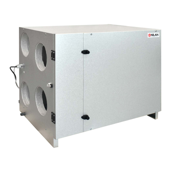
Unit type Product description Comfort 250L/350L is an energy-efficient ventilation unit with heat recovery for residential and small commercial buildings with a ventilation requirement of up to 250/372 m Comfort 250L/350L is a compact unit that can be placed in the attic. The 4 nozzles of the unit are located on the same side, which pro- vides some other options in relation to the installation. -
Page 6: Dimensional Drawing Polar
Dimensional drawing Front Left side Connections: 1. Outdoor air 2. Supply air 3. Extract air 4. Discharge air 5. Condensate drain NB! Spouts for inlet ring All listed measurements are in mm. Bottom Dimensional drawing Polar Front Left side Connections: 1. -
Page 7: Functional Block Diagram
Functional block diagram Connections 1. Outdoor air 2. Supply air 3. Extract air 4. Discharge air 5. Condensate drain 6. Electrical or water after-heating element con- nections T1 /T8 Automation T2/T7: Supply air sensor T3: Extract air sensor T4: Discharge air- and deicing sensor T1/T8: Outdoor air sensor T9: Frost protection water after-heating element sensor... -
Page 8: Accessories
Accessories Electrical pre-heating element for frost protection of the unit If your ventilation unit is not a Polar version with an integral pre-heating element, we recommend that you purchase an external pre-heating element as frost protection of the ventilation unit. During prolonged periods of frost, the high efficiency counterflow heat exchanger will ice up. -
Page 9: Expansion Pcb
Fire Connection Box The Comfort ventilation unit has a function in its control system that can control 1-2 fire dampers. If you want to activate this function, Nilan can supply you with a Fire Connection Box, with the following con- nection options: •... -
Page 10: Flexible Sound Damper
• Fire thermostat or external fire automation system You can adapt an RJ45 connector yourself in line with the instructions. To facilitate installation, Nilan can supply a 10 m LAN cable with the correct RJ45 connector for the three functions. -
Page 11: Gateway With App Option
You can control your ventilation unit with a smartphone app via a gateway connection. Connect the Nilan Gateway to a CTS400 or a CTS602 control system. This way, a cloud connection to the unit can be established. The Gateway is available in two different versions - with either a LAN or a WiFi connec-... -
Page 12: Set-Up
Set-up Installation Positioning of the ventilation unit ATTENTON When positioning the unit, you should always consider future service and maintenance. Therefore, we recommend that flexible connections be fitted between the ventilation unit and the duct system so that the unit can be easily removed. ATTENTON A free space is recommended in front of the ventilation unit of at least 60 cm. -
Page 13: Surface Level
It is important that the unit is mounted on a surface level. Duct connections An inlet ring needs to be fitted (not supplied by Nilan). 1. Use size Ø160mm inlet ring. The Polar version is deliv- 2. Press the inletrings firmly into the ventilation nozzles. -
Page 14: Electrical Installation
Electrical installation Electrical connections Safety ATTENTION All work must be carried out by qualified persons and in compliance with existing legislation and regulations. ATTENTION It is important that the power is off, if you do work to the electrical components of the unit. It is important to check that wires are not damaged or squeezed during connection and use. -
Page 15: Control Panel
ATTENTION If you want a longer cable, use a standard RJ12 shielded cable, max 50 meters. Nilan offers a 15 meter cable with plugs on both ends. Wall bracket Mount the HMI panel on the wall using the integrated wall bracket. -
Page 16: Electrical Connection Accessories
If you adapt an RJ45 cable yourself, be aware that wire 8 (Brown) can become live with 12V and must not be short circuited. In Nilan’s LAN cable the wires that are not used are not connected up to the RJ45 connector. With Nilan’s LAN cable there is therefore no risk of short circuits. -
Page 17: User Selections 1 And 2 (Cooker Hood)
In that case you can have a potential-free contact that is activated, causing ventilation to increase, for example for an hour, before operation ceases again. Connection via Nilan Functional cable 1. Green/white 2. Green User selection 1 3. Orange/white User selection 2 4. -
Page 18: Modbus
The CTS602Light control system has open Modbus RS485 communication that allows you to communicate with and control the venti- lation unit via external control systems. Please consult the software instructions and the Modbus protocol for further information on settings and registers. Connection via Nilan Functional cable 1. Green/white 2. Green 3. -
Page 19: Fire Thermostat / External Fire Automation System
When you connect up an external fire automation system, it will be necessary for the ventilation unit to restart automatically. You can set for this to happen on the control panel. Please consult the software instructions for further information. Connection via Nilan Functional cable 1. Green/white 2. - Page 20 The EM-box damper option it easy to connect up to Nilan’s CTS602 Connection Box. ATTENTION Information on connecting User selection output and GND can be found under: CTS602 Connection Box. NB: Wire for 230V power supply for the EM-box damper is not included.
-
Page 21: Dtbu (Damper Option)
DTBU damper that it is to close for extraction from other rooms. However, the damper does not close complete- ly and a reduced level of air extraction from other rooms will still take place. The DTBU damper option it easy to connect up to Nilan’s CTS602 Connection Box. ATTENTION Information on connecting User selection output and GND can be found under: CTS602 Connection Box. -
Page 22: External Electrical Pre-Heating Element
External electrical pre-heating element It is possible to purchase an external electrical pre-heating element for frost protection of the ventilation unit. The electrical pre-heating element is mounted in the outdoor air duct before the unit with the necessary temperature sensor. If it is desired to see the actual outdoor air temperature on the control panel, the temperature sensor T1 / T8 must be led out into the duct before the pre-heating element. -
Page 23: Installation Of Expansion Pcb On Cts602 Light Circuit Board
5. Connect the wires up in accordance with the wiring dia- gram. ATTENTION The expansion PCB and the connections must be installed by a certified electrician. The expansion PCB is an accessory for the CTS602 circuit board. Nilan does not supply external components. -
Page 24: Electrical After-Heating Element
Electrical after-heating element If you want to control the supply air temperature, you will need an after-heating element. You can purchase an electrical after-heating element for installation in the supply air duct. It comes with the required sensor, an ex- pansion PCB and connection to the ventilation unit. -
Page 25: Water After-Heating Element
Water after-heating element If you want to control the supply air temperature, you will need an after-heating element. You can purchase a water after-heating element for installation in the supply air duct. It comes with the required sensor, an expansion PCB and connection to the ventilation unit. -
Page 26: Joint Alarm
Joint alarm It may be difficult to notice alarms if the unit is located in a place where access is difficult or infrequent, and if the control panel is locat- ed in the same place. An external alarm indicator in the form of an electric bulb or an acoustic signal can be connected to the ventilation unit and announce when an alarm occurs. -
Page 27: Plumbing Installation
Plumbing installation Condensate drain Connection of water trap It is important that the water trap complies with the measurements below. If the water trap is placed outside the climate screen, it should be protected against frost. Ø20 mm min. 50 m min. -
Page 28: Plumbing Connections Accessories
Supply flow 2. Actuator and regulation valve Danfoss AME 140/24V 0-10V signal, 2-way valve VZ2 Kv 0.4 (Nilan supply) the Kvs value must be checked against the power supply. Differential pressure: 0.1 - 0.6 bar. With a flow temperature of 60°C and at max- imum heat output, the temperature is esti- mated to fall with 20°C over the heating... -
Page 29: Fire Automation System
It is important to check that wires are not damaged or squeezed during connection and use. Usage Nilan's fire automation system is used to monitor, test and check the fire protection components of the ventilation system: • Fire and smoke damper, and fire thermostat Important functions: •... -
Page 30: Electrical Connection Fire Automation System
Electrical connection fire automation system Connection of fire damper As an optional extra you can purchase Nilan's Fire Connection Box for connection of fire dampers. The fire automation system is integrated into the control system. Belimo fire damper Connection to the wiring harness 24 /230V AC... -
Page 31: Connecting Two Fire Dampers
EM-box/DTBU damper, Nilan can supply a Connection Box for connecting up the EM-box/DTBU damper. You can connect up the Connection Box to the Nilan Fire Connection Box (as illustrated). The fire damper is also connected up here. Connection Box for user selection and EM-box/DTBU... -
Page 32: Alarm Code
Alarm code Set an alarm 96 - "Damper test" if a position (open / closed) has not been fulfilled within the maximum moving time of 120 seconds. The test will fail if: • Current starting position (open) is incorrect • Current position (open and closed) has not altered within the first 12 seconds of moving in each direction •... -
Page 33: Schedule For Functional Testing
Schedule for functional testing ATTENTION DS428 requires written documentation of the annual test of the Fire automatic system. Date: Comments: Tested by:... -
Page 35: Ventilation Installation
This is to avoid vibrations from the unit being transmitted to the duct system. It will also make it easier to move the unit, which may be necessary during future services of the unit. Nilan can supply Soundflex tubes that you can use as flexible connections between the ventilation unit and the duct system. They will also reduce sounds from the system considerably. -
Page 36: Extract Air
Extract air Install the extract air valves in high-humidity rooms and place them strategically where they can extract humid and vitiated air from the dwelling/building most efficiently. High-humidity rooms are, for example: • Bathroom • Lavatory • Kitchen • Utility room Supply air Install supply air valves in living areas. - Page 40 25 St Leonards Road Horsham West Sussex RH13 6EH Tel: +44 (0) 14 03 56 30 45 service@slservicesgroup.com or info@slservicesgroup.com www.slservicesgroup.com Ireland: Nilan Ireland Ballylahive, Abbeydorney Tel: +353 (0) 87 97 98 361 maurice@nilan.ie www.nilanireland.ei Nilan A/S Nilanvej 2 8722 Hedensted Danmark Tlf.
Need help?
Do you have a question about the Comfort 350L and is the answer not in the manual?
Questions and answers