
Related Manuals for Intel Coffee Lake S


Summary of Contents for Intel Coffee Lake S
- Page 1 Coffee Lake S Reference Validation Platform (RVP) Customer Reference Board (CRB) User Guide Revision 2.0 May 2018 Intel Confidential Document Number: 572913...
- Page 2 All information provided here is subject to change without notice. Contact your Intel representative to obtain the latest Intel product specifications and roadmaps.
-
Page 3: Table Of Contents
Rework to Enable Vertical USB Port ........... 43 8.2.2 Rework to Enable TTK Glider Card in eSPI Mode ......46 8.2.3 Rework to Enable CNVi Module ..........50 8.2.4 Rework to Enable PCH XDP ............52 Intel Confidential User Guide... - Page 4 Rework to Enable Higher Current Profile on Front Panel USB-C Titan Ridge AIC ................93 8.4.2 Rework to Enable Sx Wake on Front Panel USB-C Titan Ridge AIC . 94 8.4.3 Rework to Enable RTD3 Flow on Front Panel USBC Titan Ridge AIC 95 Intel Confidential User Guide...
- Page 5 Figures Figure 1. Coffee Lake S DDR4 RVP Block Diagram (Shown UDIMM Only) ........11 Figure 2. DDR4 Memory Topology Diagram (Shows Only UDIMM) ..........14 Figure 3. Clock ........................15 Figure 4. Display Feature Block Diagram ................16 Figure 5. PCIe* Mapping ..................... 16 Figure 6.
- Page 6 Table 6. Rework Detail ....................... 52 Table 7. Rework Detail ....................... 56 Table 8. Rework Detail ....................... 59 Table 9. Rework Detail ....................... 63 Table 10. Rework Detail ...................... 66 Table 11. Rework Detail ...................... 70 Intel Confidential User Guide...
- Page 7 Table 18. Rework Detail ...................... 88 Table 19. Rework Detail ...................... 90 Table 20. Rework Detail ...................... 91 Table 21. Rework Detail ...................... 93 Table 22. Rework Detail ...................... 94 Table 23. Rework Detail ...................... 96 Intel Confidential User Guide...
-
Page 8: Revision History
Layout snapshot. • Added Sections – 8.1.2 • Updated WO# February 2018 • Added Figure Figure 65 updated Table 12 in section 8.2.10 • Added section 8.4.3 May 2018 • Updated WO# §§ Intel Confidential User Guide... -
Page 9: Introduction
Fast Infra-Red GPIO General Purpose Input Output GSPI Generic Serial Peripheral Interface Platform Controller Hub Integrated Device Electronics Inter-Integrated Circuit Inter-IC Sound Keyboard Controller Local Area Network Light Emitting Diode Low Pin Count Multi- Chip –Package Intel Confidential User Guide... -
Page 10: Reference Documents
Universal Serial Bus Video Graphics Array Voltage Regulator Embedded Controller Extended Debug Port Reference Documents Document Title CCL# Coffee Lake S Platform UDIMM RVP Technical Documentation Kit 571506 Coffee Lake S CNP Platform Design Guide 571264 §§ Intel Confidential User Guide... -
Page 11: Cfl-S Rvp Features
CFL-S RVP Features CFL-S RVP Features CFL RVP Block Diagram Refer to the below figure for Coffee Lake H DDR4 RVP block diagram. Figure 1. Coffee Lake S DDR4 RVP Block Diagram (Shown UDIMM Only) Intel Confidential User Guide... -
Page 12: Rvp Feature Set Summary
2x legacy vertical SATA cable connector (default) 1x M.2 SSD, x4 PCIe* or x1 SATA, Socket 3 Key M (default) ZPODD Connectivity WLAN M.2 Socket 1 Hybrid Key E for discrete or CNVi GBE LAN Jacksonville Thunderbolt™ Through AIC Intel Confidential User Guide... - Page 13 3.3V and 1.8V Embedded Controller eSPI based EC device down only. Power Delivery Discrete iMVP8 VR with ATX Power supply USB Power Delivery - Provider Over Type-C only connectors with 5V@3A profile OS Support Windows*, Chrome*, Linux*. §§ Intel Confidential User Guide...
-
Page 14: Key Rvp Features And Block Diagrams
The CNP-H chipset is the primary clock generator for all sub-system and CPU clocks on the CFL-S RVP. All the sub-system clocks and external clock outputs are derived through internal PLLs. A high level block diagram of the chipset clock interface is given below Intel Confidential User Guide... -
Page 15: Display Feature On Rvp
• The processor supports only 3 streaming independent and simultaneous display combinations of DP/eDP/HDMI/DVI monitors. • DDI ports can be configured either as Display port or HDMI port. • HDMI2.0 support is via External LS-PCON chip from Megachips – MDCP2800. Intel Confidential User Guide... -
Page 16: Pcie* Mapping
Key RVP Features and Block Diagrams Figure 4. Display Feature Block Diagram PCIe* Mapping Figure 5. PCIe* Mapping Intel Confidential User Guide... -
Page 17: Sata Interface
USB 2 Port Mapping CFL-S RVP USB 2.0 Port # USB2.0 Allocation Discrete USB Type C FP #1 USB3.1 Type A BP #2 Type C connector BP #1 USB3.1 Type A FP #1 USB3.1 Type A FP #2 Intel Confidential User Guide... -
Page 18: Usb-3 Mapping
Figure 7. USB-3 Mapping USB Type-C Support 1x discrete Type-C on Front panel: • Based out of PD controller and TUSB1046 active switch which are soldered on the RVP and terminated to a front panel header. Intel Confidential User Guide... -
Page 19: Audio Feature
Figure 8. Block Diagram – Audio 3.10 I2C Mapping LPSS I2C Mapping LPSS I2C0(3.3V) LPSS I2C1(3.3V) Touch Panel LPSS I2C2(muxed with SMLINK0 and ISH Onboard Sensor, Audio header, 2X3 header UART0)(1.8V) LPSS I2C3(muxed with ISH I2C2)(1.8V) Type-C PD controller, 1X7 header Intel Confidential User Guide... -
Page 20: Gspi Uart And Spi Mapping
Memory, 1X3 header, Option to PSS, PCIe* SMBUS DT Slots, DAC for AVMC, FRU, LPC TPM header, CPU XDP SMLINK0(muxed with I2C2 and ISH UART0) LAN, NFC SMLINK1 SMLINK2 Used as GPIOs SMLINK3 Used as GPIOs SMLINK4 Used as GPIOs Intel Confidential User Guide... -
Page 21: Connectivity Block
Key RVP Features and Block Diagrams 3.13 Connectivity Block Figure 9. Connectivity Block Diagram §§ Intel Confidential User Guide... -
Page 22: Rvp Reference Board Summary
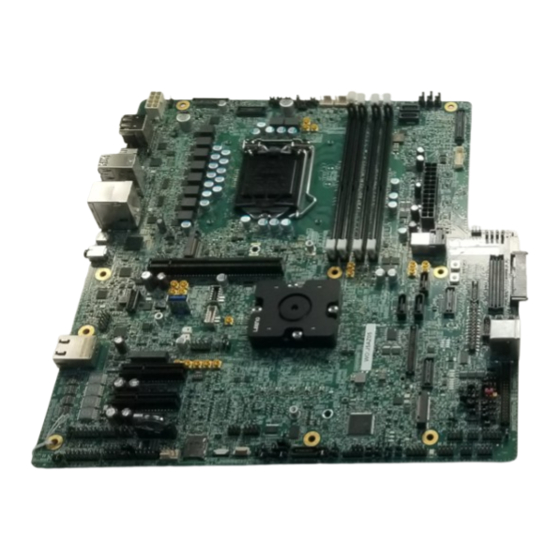
RVP Reference Board Summary RVP Reference Board Summary Figure 10. CFL RVP Reference Board – Top View Intel Confidential User Guide... -
Page 23: Figure 11. Cfl Rvp Reference Board - Bottom View
RVP Reference Board Summary Figure 11. CFL RVP Reference Board – Bottom View Figure 12. CFL RVP Reference Board – Front Side View Intel Confidential User Guide... -
Page 24: Figure 13. Cfl Rvp Reference Board - Back Panel Side View
RVP Reference Board Summary Figure 13. CFL RVP Reference Board – Back Panel Side View §§ Intel Confidential User Guide... -
Page 25: Power Sources
All PCIe* are populated − − All VR rail is under Imax Suggested power supply − • EA-550 PLATINUM (Validated by Intel PRE) • CPU Voltage Rails − IMVP8 Using Intersil* ISL95856 Core, GT only support 0V VBoot. − Core is a 4-Phase VR and GT is a 2-Phase VR. - Page 26 5V or 9V, 3A Type-C VR. − 1.2 for LSPCON supply − − CNVi rail margin VRs. Used on PnP board only • Voltage Rails with SMBUS Margin Capability − VCCSA VCCSFR_OC − VCCIO − − VDDQ §§ Intel Confidential User Guide...
-
Page 27: Hardware Assembly Instructions
Hardware Assembly Instructions Hardware Assembly Instructions CFL CPU Hardware Assembly Instructions CFL-S CPU that comes in 1151 LGA package over the H4 socket soldered down on RVP. Intel Confidential User Guide... - Page 28 3. Close the lid and hook the lever below the lid. 4. Mount the heatsink (Off-The-Shelf heatsink not supplied with RVP). • Off the shelf LGA Heatsink • Supplied with Pre-Applied Thermal Grease • 65W Heat Sink with IPN: E97379-001 Intel Confidential User Guide...
-
Page 29: Cnp-H Hardware Assembly Instructions
3 in-lb using the torque wrench and 2mm hex head. e. Ensure that the semicircular cutout in the stiffener plates is oriented in the same direction as the chamfer on the socket and Pin 1 on the board. Intel Confidential User Guide... - Page 30 Pin 1 direction of all previously installed components. Past this point, failing to line up all of the Pin 1 features in the assembly may − cause irreversible damage to the package and socket. Intel Confidential User Guide...
- Page 31 It is difficult or impossible to install the lid with the heatsink screw threaded too far down. Place the lid on top of the stiffener plate, slipping the shoulder screws through the four keyholes and turning the lid clockwise slightly to lock it in place. Intel Confidential User Guide...
- Page 32 Hardware Assembly Instructions STEP 4 – Torque the Heatsink Screw a. Using the 4mm hex driver for the torque wrench, tighten the heatsink screw to 6 in-lb. Intel Confidential User Guide...
- Page 33 Hardware Assembly Instructions §§ Intel Confidential User Guide...
-
Page 34: Quick Start Guide
Insert DDR4 UDIMM modules into UDIMM connectors (RefDes: J1E5, J1F2, J1F3, J1F4). Step3: Verify presence of RTC coin cell in Battery Holder (RefDes: XBT9C1). Step4: Insert hard disk drive in cable connect (RefDes: J6H2 or J6H1) or PCIe*/SATA based SSD in M.2 socket 3 (RefDes: J8H1). Intel Confidential User Guide... -
Page 35: Sf600 Programming
Step9: As the system boots, press F2 to enter the BIOS setup screen. Check time, date, and configuration settings. The default settings should be sufficient for most users with the exception of Intel ® Speed Step Technology. This feature is disabled by default and can be enabled in setup. -
Page 36: Spi Through Dediprog Sf600
5. Load File: After blank check operation is completed without problem, click File button. Find and open the file. If the suffix of your image is .rom, select the Data Format: ROM. If the suffix is .bin, select Data Format: Raw Binary. Finally, click Ok button. Intel Confidential User Guide... -
Page 37: Figure 15. Load File
Quick Start Guide Figure 15. Load File 6. Program and Verify: Click Batch. Finally, verify the SPI by clicking Verify button. Figure 16. Batch §§ Intel Confidential User Guide... -
Page 38: Reworks
Description of New Part Part Stuff Resistor R9D60 4.7KOhm, 5%, 0402 Un-Stuff Resistor R9D58 20KOhm, 5%, 0402 Stuff Resistor R7D12 10KOhm, 5%, 0402 Stuff Resistor R7F10, 20KOhm, 5%, 0402 R7G25 Un-Stuff Resistor R7P8 0.01Ohm, 1%, 0603, 1/10W Intel Confidential User Guide... -
Page 39: Figure 17. Schematic Snapshot
Reworks Figure 17. Schematic Snapshot Figure 18. Schematic Snapshot Intel Confidential User Guide... -
Page 40: Figure 19. Schematic Snapshot
Reworks Figure 19. Schematic Snapshot Figure 20. Layout Snapshot – Top Layer Intel Confidential User Guide... -
Page 41: Rework To Avoid Leakage From Ec To Pch In Espi Mode
1.8V SUSACK pin in the PCH in eSPI mode causing board to be stuck at EC09 POSTCODE. This rework will disconnect the SUSACK path in eSPI mode. Impact of implementing the rework: Board will boot normally after this rework in eSPI mode Intel Confidential User Guide... -
Page 42: Figure 22. Schematic Snapshot
U17612, H7AZ07, H8AZ04, H9AZ04, H7BZ06, H3BZ02, H6AZ04, H7AZ06, H9AZ02, I1AZ01, I2AZ02, I1AZ02 Table 2. Rework Detail Action Item RefDes Description of Existing Description of New Part Part Un-Stuff Resistor R9F9 0Ohm, 5%, 402, 1/10W Figure 22. Schematic Snapshot Intel Confidential User Guide... -
Page 43: Feature Enabling Reworks
Rework to Enable Vertical USB Port Description: This rework is to enable the vertical USB port Impact of implementing the rework: Vertical USB will work. The USB back panel Port 6 will not work after this rework. Details: SMT Resistor rework. Intel Confidential User Guide... -
Page 44: Figure 24. Schematic Snapshot
Description of Existing Description of New Part Part Stuff Resistor R6D69, 0 Ohm, 5%, 402 R6D66, R6E1, R6E4, R6B26, R6B23, R6B20 Un-Stuff Resistor R6D68, 0 Ohm, 5%, 402 R6D67, R6E2, R6E3, R6B25, R6B24 Figure 24. Schematic Snapshot Intel Confidential User Guide... -
Page 45: Figure 25. Schematic Snapshot
Reworks Figure 25. Schematic Snapshot Intel Confidential User Guide... -
Page 46: Rework To Enable Ttk Glider Card In Espi Mode
Details: SMT Resistor rework. Applicable To: H3AZ01, H3AZ02, H4BZ01, H5AZ02, H6AZ05, H6AZ08, H7AZ03, H7BZ03, H7AZ05, H7AZ08, H6AZ09, H7AZ02, H7BZ02, H7AZ04, H8AZ02, H8AZ03, U17612, H7AZ07, H8AZ04, H7BZ06, H3BZ02, H6AZ04, H7AZ06, H9AZ02, I1AZ01, I2AZ02, I2AZ04, I1AZ02, I3AZ03, I3AZ05, I4BZ01, I5AZ01, I3AZ04. Intel Confidential User Guide... -
Page 47: Table 4. Rework Detail
Action Item RefDes Description of Existing Description of New Part Part Stuff Resistor R9G1, 0 Ohm, 5%, 402 R9G4, R9G13, R9G16, R9G19, R9F26 Un-Stuff Resistor R9G26 22 Ohm, 5%, 402 Stuff Resistor R9G27 15Ohm, 5%, 402 Intel Confidential User Guide... -
Page 48: Figure 27. Schematic Snapshot
Reworks Figure 27. Schematic Snapshot Figure 28. Schematic Snapshot Intel Confidential User Guide... -
Page 49: Figure 29. Layout Snapshot - Top Layer
Reworks Figure 29. Layout Snapshot – Top Layer Figure 30. Layout Snapshot – Bottom Layer Intel Confidential User Guide... -
Page 50: Rework To Enable Cnvi Module
Details: Resistor unstuff and bluewiring. Applicable To: H3AZ01, H3AZ02, H4BZ01, H5AZ02, H3BZ02 Table 5. Rework Detail Action Item RefDes Description of Existing Description of New Part Part Un-Stuff Resistor R7B9 0.01, 1/10W, 1%, 0603 Figure 31. Schematic Snapshot Intel Confidential User Guide... -
Page 51: Figure 32. Schematic Snapshot
Reworks Figure 32. Schematic Snapshot Figure 33. Layout Snapshot – Top Layer Intel Confidential User Guide... -
Page 52: Rework To Enable Pch Xdp
I2AZ02, I2AZ04, I1AZ02, I3AZ03, I3AZ05, I4BZ01, I5AZ01, I3AZ04. Table 6. Rework Detail Action Item RefDes Description of Description of New Existing Part Part Un-Stuff Resistor R7F13, R6T11, 0 Ohm, 5%, 402 R5J33, R6F28, R6T10, R6F1, R5J6, R5J10, Intel Confidential User Guide... -
Page 53: Figure 35. Schematic Snapshot
Existing Part Part Stuff Resistor R6T8, R5J8, 0 Ohm, 5%, 402 R5J7, R5J5, R5J4, R5J3, R5J2, R5J1, R6F13, R5J29, R5J34, R5J27, R5J26, R5J32, R5J24, R6F29, R5J23, R5J22 Stuff Resistor R5J21 0Ohm, 5%, 603 Figure 35. Schematic Snapshot Intel Confidential User Guide... -
Page 54: Figure 36. Schematic Snapshot
Reworks Figure 36. Schematic Snapshot Figure 37. Schematic Snapshot Intel Confidential User Guide... -
Page 55: Figure 38. Layout Snapshot - Top Layer
Reworks Figure 38. Layout Snapshot – Top Layer Figure 39. Layout Snapshot – Bottom Layer Intel Confidential User Guide... -
Page 56: Rework For External Speaker Amplifier In Hda Mode
Table 7. Rework Detail Action Item RefDes Description of Description of New Existing Part Part Un-Stuff Resistor R9A14, 0 Ohm, 5%, 402 R9B7 Stuff Resistor R9A12 0 Ohm, 5%, 0603 Stuff Resistor R7A23, R7A33, 100KOhm, 5%, 0402 R9A15, R9B8 Intel Confidential User Guide... -
Page 57: Figure 40. Schematic Snapshot
Reworks Figure 40. Schematic Snapshot Figure 41. Schematic Snapshot Intel Confidential User Guide... -
Page 58: Rework For Enabling Front Panel Usbc Titan Ridge Aic
Impact of implementing the rework: Default TR SP back panel would be enabled. After rework FP TR DP AIC would be enabled and BP TR SP will not work. Details: SMD Resistor/Capacitor rework Applicable To: H3AZ01, H3AZ02, H4BZ01, H3BZ02. Intel Confidential User Guide... -
Page 59: Figure 43. Schematic Snapshot
0 Ohm, 5%, 402 6E11,R6E13,R6E17, R6E19,R6E23, R6E28,R6E32, R6E26,R6E30, R6E20,R6E24, R6E37,R6E35, R6P5,R6P8,R7R38, R5A42, R5L14, R5L22, R5L11, R8G15, R6F27 Stuff Resistor R6E9,R6E7,R6E14,R 0 Ohm, 5%, 402 6E10,R6E12,R6E16, R6E18,R6E22, R6E29,R6E33, R6E27,R6E31, R6E21,R6E25, R6E36,R6E34, R6P6,R6P7,R7R40, R2TR,R8H13,R5L15, R8H11,R5L12,R8G1 6,R6F21,R6F25 Figure 43. Schematic Snapshot Intel Confidential User Guide... -
Page 60: Figure 44. Schematic Snapshot
Reworks Figure 44. Schematic Snapshot Figure 45. Schematic Snapshot Intel Confidential User Guide... -
Page 61: Figure 46. Layout Snapshot - Top Layer
Reworks Figure 46. Layout Snapshot – Top Layer Intel Confidential User Guide... -
Page 62: Rework For Enabling Back Panel Usbc Titan Ridge
Details: SMD Resistor/Capacitor rework Applicable To: H5AZ02, H6AZ05, H6AZ08, H7AZ03, H7BZ03, H7AZ05, H7AZ08, H6AZ09, H7AZ02, H7BZ02, H7AZ04, H8AZ02, H8AZ03, U17612, H7AZ07, H8AZ04, H7BZ06, H3BZ02, H6AZ04, H7AZ06, H9AZ02, I1AZ01, I2AZ02, I2AZ04, I1AZ02, I3AZ03, I3AZ05, I4BZ01, I5AZ01, I3AZ04. Intel Confidential User Guide... -
Page 63: Table 9. Rework Detail
0 Ohm, 5%, 402 6E11,R6E13,R6E17, R6E19,R6E23, R6E28,R6E32, R6E26,R6E30, R6E20,R6E24, R6E37,R6E35, R6P5,R6P8,R7R38, R5A42, R5L14, R5L22, R5L11, R8G15, R6F27 Stuff Resistor R6E8,R6E6,R6E15,R 0 Ohm, 5%, 402 6E11,R6E13,R6E17, R6E19,R6E23, R6E28,R6E32,R6E2 6,R6E30,R6E20,R6E 24,R6E37,R6E35, R6P5,R6P8,R7R38, R5A42, R5L14, R5L22, R5L11, R8G15, R6F27, R1TR Intel Confidential User Guide... -
Page 64: Figure 48. Schematic Snapshot
Reworks Figure 48. Schematic Snapshot Figure 49. Schematic Snapshot Intel Confidential User Guide... -
Page 65: Figure 50. Schematic Snapshot
Reworks Figure 50. Schematic Snapshot Figure 51. Layout Snapshot – Top Layer Intel Confidential User Guide... -
Page 66: Rework To Enable Audio In Soundwire* Mode
I3AZ03, I3AZ05, I4BZ01, I5AZ01, I3AZ04. Table 10. Rework Detail Action Item RefDes Description of Description of New Existing Part Part Un-Stuff Resistor R7E2, R7E4, R7E7, 0 Ohm, 5%, 402 R7E8,R9A15,R9B8 Stuff Resistor R9A14, R9B7 0 Ohm, 5%, 402 Intel Confidential User Guide... -
Page 67: Figure 53. Schematic Snapshot
Reworks Action Item RefDes Description of Description of New Existing Part Part Un-stuff Resistor R7A19 100k Ohm, 5%, 402 Stuff Resistor R7A15 100k Ohm, 5%, 402 Figure 53. Schematic Snapshot Intel Confidential User Guide... -
Page 68: Figure 54. Schematic Snapshot
Reworks Figure 54. Schematic Snapshot Intel Confidential User Guide... -
Page 69: Figure 55. Schematic Snapshot
Reworks Figure 55. Schematic Snapshot Intel Confidential User Guide... -
Page 70: Rework To Enable Audio Hda Mode On Header
H7BZ06, H3BZ02, H6AZ04, H7AZ06, H9AZ02, I1AZ01, I2AZ02, I2AZ04, I1AZ02, I3AZ03, I3AZ05, I4BZ01, I5AZ01, I3AZ04. Table 11. Rework Detail Action Item RefDes Description of Description of New Existing Part Part Un-Stuff Resistor R7E2, R7E4, R7E7, 0 Ohm, 5%, 402 R7E8 Intel Confidential User Guide... -
Page 71: Figure 57. Schematic Snapshot
Reworks Action Item RefDes Description of Description of New Existing Part Part Stuff Resistor R7E1, R7E5, R7E6, 0 Ohm, 5%, 402 R7E9 Stuff Resistor R9A12 0 Ohm, 5%, 603 Figure 57. Schematic Snapshot Intel Confidential User Guide... -
Page 72: Rework To Enable Lpc Mode For Ec And Tpm Header
H7BZ06, H3BZ02, H6AZ04, H7AZ06, H9AZ02, I1AZ01, I2AZ02, I2AZ04, I1AZ02, I3AZ03, I3AZ05, I4BZ01, I5AZ01, I3AZ04. Table 12. Rework Detail Action Item RefDes Description of Description of New Existing Part Part Un-Stuff Resistor R8G50, R9F40, 0 Ohm, 5%, 402 R9F38, R8F7, R7E44 Intel Confidential User Guide... - Page 73 Un-Stuff Resistor R7R25 0.1 Ohm, 1%, 603 Stuff Resistor R8E3 1k Ohm, 5%, 402 Un-Stuff Resistor R8E1 1k Ohm, 5%, 402 Replace Resistor R7R31, R7R41, 15 Ohm, 5%, 402 0 Ohm, 5%, 402 R7R36, R7R37, R7R42 Intel Confidential User Guide...
-
Page 74: Figure 59. Schematic Snapshot
Reworks Figure 59. Schematic Snapshot Figure 60. Schematic Snapshot Intel Confidential User Guide... -
Page 75: Figure 61. Schematic Snapshot
Reworks Figure 61. Schematic Snapshot Figure 62. Schematic Snapshot Intel Confidential User Guide... -
Page 76: Figure 63. Layout Snapshot - Top Layer
Reworks Figure 63. Layout Snapshot – Top Layer Snapshot-2 Snapshot-3 Below zoomed-in picture is Snapshot-2 Below zoomed-in Picture is Snapshot-3 Intel Confidential User Guide... -
Page 77: Figure 64. Layout Snapshot - Bottom Layer
Reworks Figure 64. Layout Snapshot – Bottom Layer Figure 65. Layout Snapshot – Top Layer Intel Confidential User Guide... - Page 78 Reworks Intel Confidential User Guide...
-
Page 79: Rework To Enable V1P8A Source From Pch Internal Ldo To External Vr
I3AZ03, I3AZ05, I4BZ01, I5AZ01, I3AZ04. Table 13. Rework Detail Action Item RefDes Description of Description of New Existing Part Part Resistor R6R3 PCB Etch Short Trace Stuff Resistor R7P8 10mOhm, 1%, 402 Figure 66. Schematic Snapshot Intel Confidential User Guide... -
Page 80: Rework To Enable Audio Header For I2S Mode
Applicable To: H6AZ05, H6AZ08, H7AZ03, H7BZ03, H7AZ05, H7AZ08, H6AZ09, H7AZ02, H7BZ02, H7AZ04, H8AZ02, H8AZ03, U17612, H7AZ07, H8AZ04, H9AZ04, H7BZ06, H3BZ02, H6AZ04, H7AZ06, H9AZ02, I1AZ01, I2AZ02, I2AZ04, I3AZ03, I3AZ05, I4BZ01, I5AZ01, I1AZ02, I3AZ04. This rework will not work in H3AZ01, H3AZ02, H4BZ01, H5AZ02 and H3BZ02. Intel Confidential User Guide... -
Page 81: Figure 68. Schematic Snapshot
R7E9, R8A20, R8A23, R9A5, R9A7, R8E4, R8D40, R7R22 Unstuff Resistor R7E2, R7E4, R7E7, 0 ohm, 5%, 402 R7E8, R8A22, R9A9, R9A8 Replace Resistor R9A11 20 Ohm, 5%, 402 0 Ohm, 5%, 402 Figure 68. Schematic Snapshot Intel Confidential User Guide... -
Page 82: Figure 69. Schematic Snapshot
Reworks Figure 69. Schematic Snapshot Figure 70. Schematic Snapshot Intel Confidential User Guide... -
Page 83: Optional Reworks
Applicable To: H3AZ01, H3AZ02, H4BZ01, H3BZ02 Table 15. Rework Detail Action Item RefDes Description of Existing Description of New Part Part Stuff Resistor R3A7 0 Ohm, 5%, 402 Replace Resistor R2A12 10kOhm, 1%, 402, 1/16W 100kOhm, 1%, 402, 1/10W Intel Confidential User Guide... -
Page 84: Figure 72. Schematic Snapshot
Reworks Figure 72. Schematic Snapshot Figure 73. Layout Snapshot – Top Layer Intel Confidential User Guide... -
Page 85: Rework To Enable Titan Ridge And Pd's Flash
Applicable To: H3AZ01, H3AZ02, H3BZ02 Table 16. Rework Detail Action Item RefDes Description of Existing Description of New Part Part Stuff Resistor R5A17 0Ohm, 1%, 402, 1/16W Un-Stuff Resistor R5L28 0Ohm, 5%, 402, 1/16W Figure 74. Schematic Snapshot Intel Confidential User Guide... -
Page 86: Rework To Keep Usb Compliant On Fp Discrete Type C
Rework to Keep USB Compliant on FP Discrete Type C Description: This rework is keep the USB PDG compliant with the active switch datasheet and Intel PDG. Impact of implementing the rework: The resistor on Tx lanes between PCH and type C active switch needs to be replaced with 0.1uf to keep it compliant with the... -
Page 87: Figure 77. Schematic Snapshot
Applicable To: H3AZ01, H3AZ02, H4BZ01, H5AZ02, H3BZ02 Table 17. Rework Detail Action Item RefDes Description of Existing Description of New Part Part Replace Resistor R6D41, 0Ohm, 5%, 402, 1/16W 0.1uf, 5%, 402, 25V R6D40 Figure 77. Schematic Snapshot Intel Confidential User Guide... -
Page 88: Rework To Enable Debug Consent Strap
Applicable To: H3AZ01, H3AZ02, H4BZ01, H5AZ02, H6AZ05, H6AZ08, H7AZ03, H7BZ03, H6AZ09, H7AZ02, H7BZ02, U17612, H3BZ02, H6AZ04, Table 18. Rework Detail Action Item RefDes Description of Existing Description of New Part Part Un-Stuff Resistor R7G23, 1kOhm, 5%, 402, 1/16W R7G34 Intel Confidential User Guide... -
Page 89: Bias Resistor Pdg Compliance For 24Mhz Clock
BIAS Resistor PDG Compliance for 24MHz Clock Description: This rework is keep the 24MHz clock’s bias resistor compliant as per Impact of implementing the rework: The current 1MOhm resistor is to be replaced with 200kohm resistor Intel Confidential User Guide... -
Page 90: Figure 81. Schematic Snapshot
Applicable To: H3AZ01, H3AZ02, H4BZ01, H5AZ02, H6AZ05, H6AZ08, U17612, H3BZ02, H6AZ04, Table 19. Rework Detail Action Item RefDes Description of Existing Description of New Part Part Replace Resistor R6D55 1MOhm, 5%, 402, 1/16W 200kOhm, 1%, 402, 1/16W Figure 81. Schematic Snapshot Intel Confidential User Guide... -
Page 91: Rework To Avoid Leakage On Cnvi And Dmic Modules
Description of Existing Description of New Part Part Un-Stuff Resistor R7R17 0.022Ohm, 5%, 402, 1/16W Stuff Resistor R7R18 0.022Ohm, 5%, 402, 1/16W Un-Stuff Resistor R7R20 0Ohm, 1%, 402, 1/16W Stuff Resistor R7R21 0Ohm, 1%, 402, 1/16W Intel Confidential User Guide... -
Page 92: Aic Reworks
Reworks Figure 83. Schematic Snapshot Figure 84. Layout Snapshot – Top Layer AIC Reworks Note: Resistor THR99 is to be replaced with 0 Ohm, 5%, 0402. This is applicable to U17221, H6AZ03, H6AZ06, H7AZ01 AIC boards. Intel Confidential User Guide... -
Page 93: Rework To Enable Higher Current Profile On Front Panel Usb-C Titan Ridge Aic
Details: SMD Resistor rework. Applicable To: U17221, H6AZ03, H6AZ06, H7AZ01. Table 21. Rework Detail Action Item RefDes Description of Existing Description of New Part Part Replace Resistor BTR11 49.9K 0402 174K, 0402, 1% Figure 85. Schematic Snapshot Intel Confidential User Guide... -
Page 94: Rework To Enable Sx Wake On Front Panel Usb-C Titan Ridge Aic
Details: SMD Resistor rework. Applicable To: U17221, H6AZ03, H6AZ06, H7AZ01, HAAZ01, HCAZ01. Table 22. Rework Detail Action Item RefDes Description of Existing Description of New Part Part Un-stuff Resistor THR66, 0 Ohm,0402,5% THR70 Stuff Resistor THR69 0 Ohm,0402,5% Intel Confidential User Guide... -
Page 95: Rework To Enable Rtd3 Flow On Front Panel Usbc Titan Ridge Aic
3.3V Dual pull up. Impact of implementing the rework: When trying to do Sx Wake with TBT device connected, CAT error/Device getting lost behavior is observed without this rework Details: SMD Resistor and blue wire rework. Intel Confidential User Guide... -
Page 96: Figure 89. Schematic Snapshot
Reworks Applicable To: U17221, H6AZ03, H6AZ06, H7AZ01, HAAZ01, HCAZ01. Table 23. Rework Detail Action Item RefDes Description of Existing Description of New Part Part Un-stuff Resistor THR28 10k Ohm,0402,5% Resistor 10k Ohm,0402,5% Figure 89. Schematic Snapshot Intel Confidential User Guide... -
Page 97: Figure 90. Layout Snapshot - Bottom Layer
Reworks Figure 90. Layout Snapshot – Bottom Layer §§ Intel Confidential User Guide...
Need help?
Do you have a question about the Coffee Lake S and is the answer not in the manual?
Questions and answers