Sign In
Upload
Manuals
Brands
Intel Manuals
Computer Hardware
Coffee Lake S
Intel Coffee Lake S Manuals
Manuals and User Guides for Intel Coffee Lake S. We have
1
Intel Coffee Lake S manual available for free PDF download: User Manual
Intel Coffee Lake S User Manual (97 pages)
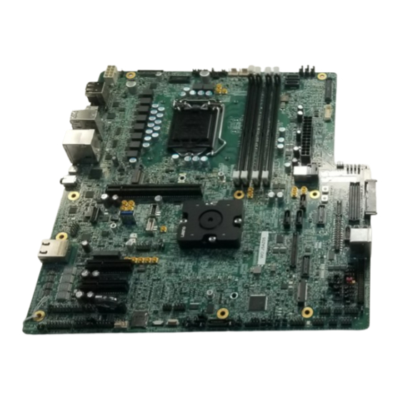
Reference Validation Platform (RVP) Customer Reference Board (CRB)
Brand:
Intel
| Category:
Computer Hardware
| Size: 19 MB
Table of Contents
Table of Contents
3
Revision History
8
Introduction
9
Terminology
9
Reference Documents
10
CFL-S RVP Features
11
CFL RVP Block Diagram
11
Figure 1. Coffee Lake S DDR4 RVP Block Diagram (Shown UDIMM Only)
11
RVP Feature Set Summary
12
Key RVP Features and Block Diagrams
14
DDR4 Memory Topology
14
Clock
14
Figure 2. DDR4 Memory Topology Diagram (Shows Only UDIMM)
14
Display Feature on RVP
15
Figure 3. Clock
15
Pcie* Mapping
16
Figure 4. Display Feature Block Diagram
16
Figure 5. Pcie* Mapping
16
SATA Interface
17
USB 2 Port Mapping
17
Figure 6. SATA Mapping - Block Diagram
17
USB-3 Mapping
18
USB Type-C Support
18
Figure 7. USB-3 Mapping
18
Audio Feature
19
I2C Mapping
19
Figure 8. Block Diagram - Audio
19
GSPI UART and SPI Mapping
20
SMBUS/SMLINK Mapping
20
Connectivity Block
21
Figure 9. Connectivity Block Diagram
21
RVP Reference Board Summary
22
Figure 10. CFL RVP Reference Board - Top View
22
Figure 11. CFL RVP Reference Board - Bottom View
23
Figure 12. CFL RVP Reference Board - Front Side View
23
Figure 13. CFL RVP Reference Board - Back Panel Side View
24
Power Sources
25
PSU Requirements
25
Hardware Assembly Instructions
27
CFL CPU Hardware Assembly Instructions
27
CNP-H Hardware Assembly Instructions
29
Quick Start Guide
34
Peripherals Required before Power on the Board
34
Board Bring-Up Steps
34
SF600 Programming
35
SPI through Dediprog SF600
36
Steps for SPI Programming
36
Figure 14 SPI through Dediprog SF600
36
Figure 15. Load File
37
Figure 16. Batch
37
Reworks
38
Mandatory Reworks
38
Straps to Power on the Board
38
Table 1. Rework Detail
38
Figure 17. Schematic Snapshot
39
Figure 18. Schematic Snapshot
39
Figure 19. Schematic Snapshot
40
Figure 20. Layout Snapshot - Top Layer
40
Rework to Avoid Leakage from EC to PCH in Espi Mode
41
Figure 21. Layout Snapshot - Bottom
41
Figure 22. Schematic Snapshot
42
Table 2. Rework Detail
42
Feature Enabling Reworks
43
Rework to Enable Vertical USB Port
43
Figure 23. Layer Snapshot - Top
43
Figure 24. Schematic Snapshot
44
Table 3. Rework Detail
44
Figure 25. Schematic Snapshot
45
Rework to Enable TTK Glider Card in Espi Mode
46
Figure 26. Layout Snapshot - Top Layer
46
Table 4. Rework Detail
47
Figure 27. Schematic Snapshot
48
Figure 28. Schematic Snapshot
48
Figure 29. Layout Snapshot - Top Layer
49
Figure 30. Layout Snapshot - Bottom Layer
49
Rework to Enable Cnvi Module
50
Figure 31. Schematic Snapshot
50
Table 5. Rework Detail
50
Figure 32. Schematic Snapshot
51
Figure 33. Layout Snapshot - Top Layer
51
Rework to Enable PCH XDP
52
Figure 34. Layout Snapshot - Top Layer
52
Table 6. Rework Detail
52
Figure 35. Schematic Snapshot
53
Figure 36. Schematic Snapshot
54
Figure 37. Schematic Snapshot
54
Figure 38. Layout Snapshot - Top Layer
55
Figure 39. Layout Snapshot - Bottom Layer
55
Rework for External Speaker Amplifier in HDA Mode
56
Table 7. Rework Detail
56
Figure 40. Schematic Snapshot
57
Figure 41. Schematic Snapshot
57
Rework for Enabling Front Panel USBC Titan Ridge AIC
58
Figure 42. Layout Snapshot - Top Layer
58
Figure 43. Schematic Snapshot
59
Table 8. Rework Detail
59
Figure 44. Schematic Snapshot
60
Figure 45. Schematic Snapshot
60
Figure 46. Layout Snapshot - Top Layer
61
Rework for Enabling Back Panel USBC Titan Ridge
62
Figure 47. Layout Snapshot - Bottom Layer
62
Table 9. Rework Detail
63
Figure 48. Schematic Snapshot
64
Figure 49. Schematic Snapshot
64
Figure 50. Schematic Snapshot
65
Figure 51. Layout Snapshot - Top Layer
65
Rework to Enable Audio in Soundwire* Mode
66
Figure 52. Layout Snapshot - Bottom Layer
66
Table 10. Rework Detail
66
Figure 53. Schematic Snapshot
67
Figure 54. Schematic Snapshot
68
Figure 55. Schematic Snapshot
69
Rework to Enable Audio HDA Mode on Header
70
Figure 56. Layout Snapshot - Top Layer
70
Table 11. Rework Detail
70
Figure 57. Schematic Snapshot
71
Rework to Enable LPC Mode for EC and TPM Header
72
Figure 58. Layout Snapshot - Top Layer
72
Table 12. Rework Detail
72
Figure 59. Schematic Snapshot
74
Figure 60. Schematic Snapshot
74
Figure 61. Schematic Snapshot
75
Figure 62. Schematic Snapshot
75
Figure 63. Layout Snapshot - Top Layer
76
Figure 64. Layout Snapshot - Bottom Layer
77
Figure 65. Layout Snapshot - Top Layer
77
Rework to Enable V1P8A Source from PCH Internal LDO to External VR
79
Figure 66. Schematic Snapshot
79
Table 13. Rework Detail
79
Rework to Enable Audio Header for I2S Mode
80
Figure 67. Layout Snapshot
80
Figure 68. Schematic Snapshot
81
Table 14. Rework Detail
81
Figure 69. Schematic Snapshot
82
Figure 70. Schematic Snapshot
82
Optional Reworks
83
Rework to Enable Gated CLKREQ for LAN
83
Figure 71. Layout Snapshot - Top Layer
83
Table 15. Rework Detail
83
Figure 72. Schematic Snapshot
84
Figure 73. Layout Snapshot - Top Layer
84
Rework to Enable Titan Ridge and Pd's Flash
85
Figure 74. Schematic Snapshot
85
Table 16. Rework Detail
85
Rework to Keep USB Compliant on FP Discrete Type C
86
Figure 75. Layout Snapshot - Top Layer
86
Figure 76. Layout Snapshot - Bottom Layer
86
Figure 77. Schematic Snapshot
87
Table 17. Rework Detail
87
Rework to Enable Debug Consent Strap
88
Figure 78. Layout Snapshot - Top Layer
88
Table 18. Rework Detail
88
BIAS Resistor PDG Compliance for 24Mhz Clock
89
Figure 79. Schematic Snapshot
89
Figure 80. Layout Snapshot - Top Layer
89
Figure 81. Schematic Snapshot
90
Table 19. Rework Detail
90
Rework to Avoid Leakage on Cnvi and DMIC Modules
91
Figure 82. Layout Snapshot - Top Layer
91
Table 20. Rework Detail
91
AIC Reworks
92
Figure 83. Schematic Snapshot
92
Figure 84. Layout Snapshot - Top Layer
92
Rework to Enable Higher Current Profile on Front Panel USB-C Titan Ridge AIC
93
Figure 85. Schematic Snapshot
93
Table 21. Rework Detail
93
Rework to Enable Sx Wake on Front Panel USB-C Titan Ridge AIC
94
Figure 86. Layout Snapshot - Top Layer
94
Table 22. Rework Detail
94
Rework to Enable RTD3 Flow on Front Panel USBC Titan Ridge AIC
95
Figure 87. Schematic Snapshot
95
Figure 88. Layout Snapshot - Top Layer
95
Figure 89. Schematic Snapshot
96
Table 23. Rework Detail
96
Figure 90. Layout Snapshot - Bottom Layer
97
Advertisement
Advertisement
Related Products
Intel Intel CoreTM Duo Processor
Intel Core 2 Duo Processor
Intel Core2 Duo E6000 Series
Intel Core2 Quad Q9000 Series
Intel Core2 Quad Q8000 Series
Intel Core2 Quad Q8000S Series
Intel Core2 Extreme quad-core QX6000 series
Intel Core2 Quad Q6000 series
Intel Core 2 Extreme
Intel Core 2 Solo
Intel Categories
Motherboard
Computer Hardware
Server
Desktop
Server Board
More Intel Manuals
Login
Sign In
OR
Sign in with Facebook
Sign in with Google
Upload manual
Upload from disk
Upload from URL