Table of Contents
Advertisement
Quick Links
Installation and Operation Guide
Non-Bubbler
Manual #694303070 of Assembly #604304036
Copyright © 2021. All rights reserved, Teledyne ISCO
Revision M, November 2021
Use and Disclosure of Data Information contained herein is classified as EAR99 under the U.S. Export Administration
Regulations. Export, reexport or diversion contrary to U.S. law is prohibited.
Advertisement
Table of Contents
Troubleshooting

Related Manuals for Teledyne TIENet Signature


Summary of Contents for Teledyne TIENet Signature
- Page 1 Installation and Operation Guide Non-Bubbler Manual #694303070 of Assembly #604304036 Copyright © 2021. All rights reserved, Teledyne ISCO Revision M, November 2021 Use and Disclosure of Data Information contained herein is classified as EAR99 under the U.S. Export Administration Regulations. Export, reexport or diversion contrary to U.S. law is prohibited.
-
Page 3: Contact Information
Teledyne ISCO recommends that you read this manual completely before placing the equipment in service. Although Teledyne ISCO designs reliability into all equipment, there is always the possibility of a malfunction. This manual may help in diagnosing and repairing the malfunction. - Page 5 Signature® Flow Meter Safety Signature® Flow Meter Safety General Warnings Before installing, operating, or maintaining this equipment, it is imperative that all hazards and preventive measures are fully understood. While specific hazards may vary according to location and application, take heed of the following general warnings: WARNING Avoid hazardous practices! If you use this instrument in...
- Page 6 Signature® Flow Meter Safety The equipment and this manual use symbols used to warn of Hazard Symbols hazards. The symbols are explained below. Hazard Symbols Warnings and Cautions The exclamation point within the triangle is a warning sign alerting you of important instructions in the instrument’s technical reference manual.
-
Page 7: Table Of Contents
Signature Flow Meter ® Table of Contents Section 1 Introduction 1.1 Quick Start ............1-2 1.2 Data Integrity . - Page 8 Signature® Flow Meter Table of Contents 2.8 Administration ........... . 2-30 2.8.1 Language Options .
- Page 9 Signature® Flow Meter Table of Contents Section 5 Equipment Options 5.1 AC Power Cord Kit /AC Wiring (Applies to Permanent Installation Only) ..5-2 5.2 Battery Backup (Applies to Permanent Installation Only) ....5-4 5.3 Power Loss Alarm .
- Page 10 Signature® Flow Meter Table of Contents Appendix A Replacement Parts A.1 How to Order............A-1 A.2 Flow Meter .
- Page 11 Signature® Flow Meter Table of Contents List of Figures 1-1 Signature Flow Meter ..........1-1 1-2 Multiple options can be used in any combination .
- Page 12 Signature® Flow Meter Table of Contents 4-4 Signature tilted up in preparation of removal ......4-3 4-5 Signature in upward facing position .
- Page 13 Signature® Flow Meter Table of Contents 6-8 Opening the desiccant cartridge chambers ....... 6-7 6-9 Front cover (door) replacement .
- Page 14 Signature® Flow Meter Table of Contents...
-
Page 15: Signature ® Flow Meter
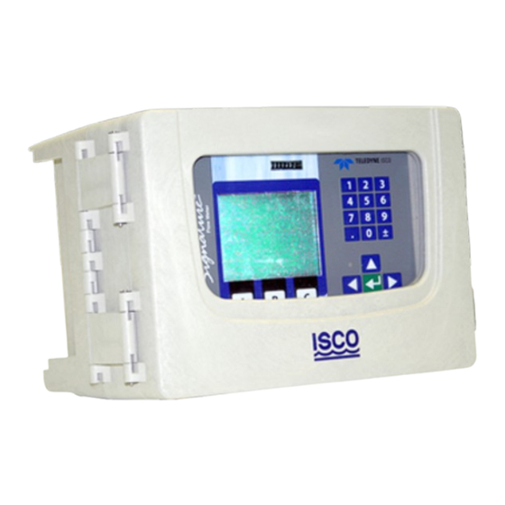
Signature Flow Meter ® Section 1 Introduction The Signature Flow Meter is designed for open channel flow monitoring applications using any combination of flow and parameter measurement technologies and sampling, depending on what is required at the monitoring site. The Signature has built-in standard level-to-flow conversions that cover the majority of open channel flow measurement situa- tions. -
Page 16: Quick Start
® Signature Flow Meter Section 1 Introduction 1.1 Quick Start Enter: . . . Numerical: • Enter values • Type characters • Open list • Confirm selection • Activate field Arrows: . . . • = Pull down list available •... -
Page 17: Data Integrity
® ously with TIENet connectivity (up to nine TIENet devices). The flow meter can also communicate with an optional Teledyne ISCO wastewater sampler and rain gauges. For descriptions of interfacing and parameter sensing TIENet devices, refer to Section 5 Equipment Options. Each external TIENet device comes with its own user manual. - Page 18 ® Signature Flow Meter Section 1 Introduction When connected remotely via modem, the web interface of the Signature Flow Meter provides remote control and data access. Figure 1-2 Multiple options can be used in any combination...
-
Page 19: Identifying Signature Components
® Signature Flow Meter Section 1 Introduction 1.5 Identifying Signature The following are key components of the Signature Flow Meter: Components Injection molded UV protected sturdy enclosure USB Cable Connector Desiccant Holder (Used with TIENet 330 Bubbler, TIENet 350 AV Sensors, and 360 Laser Flow) to bubbler air supply... -
Page 20: Controls And Indicators
® Signature Flow Meter Section 1 Introduction 1.6 Controls and Before programming and operating the Signature Flow Meter, become familiar with the keypad and standard screens. Indicators Keys are identified in Figure 1-4; keypad functions are detailed 1.6.1 Keypad in Section 2.1.1. User-programmed name Non-resettable Numerical keys (12) -
Page 21: Display And Led
® Signature Flow Meter Section 1 Introduction The LED on the front panel is aligned next to the Status line on 1.6.2 Display and LED the display screen. • A green light indicates that new information is available for viewing in the Status line. •... - Page 22 (Operation and Storage) NOTE — The operating ambient temperature range of the optional mechan- ical totalizer (see Section 5.4) is -10 to 60 °C (14 to 140 °F). Optional Teledyne ISCO TIENet 306 device Sampler Interfacing Output: Flow pacing, Enabling on trigger...
- Page 23 ® Signature Flow Meter Section 1 Introduction Table 1-1 Signature Flow Meter Technical Specifications (Continued) Optional 307 TIENet Analog Input: Configurable either active (signature supplying loop power) or passive (rely- ing on loop power, signature is not powering the loop). Output voltage (in active mode) 17 VDC minimum Range...
- Page 24 ® Signature Flow Meter Section 1 Introduction Figure 1-5 Specification drawing: Signature Flow Meter with stand in side facing position 1-10...
- Page 25 ® Signature Flow Meter Section 1 Introduction Figure 1-6 Specification drawing: Signature Flow Meter with stand in upward facing position 1-11...
-
Page 26: Specification Drawing: Signature Bubbler Flow Meter
® Signature Flow Meter Section 1 Introduction Figure 1-7 Specification drawing: Signature Bubbler Flow Meter, 1 of 2 1-12... - Page 27 ® Signature Flow Meter Section 1 Introduction Figure 1-8 Specification drawing: Signature Bubbler Flow Meter, 2 of 2 1-13...
- Page 28 ® Signature Flow Meter Section 1 Introduction 1-14...
-
Page 29: Signature ® Flow Meter
The Signature Flow Meter can be set up, programmed, and inter- rogated directly through the keypad and display screen, or remotely using a computer equipped with Teledyne Isco’s Flowlink® software, with either a USB cable or optional modem. The Signature Flow Meter has its own browser, accessed via Flowlink, that mirrors the physical keypad and display. -
Page 30: Connecting To The Signature With Flowlink
® Signature Flow Meter Section 2 Setup and Programming The home key returns the flow meter to the home screen from any other screen. The delete key clears the last character entry, exits a pull down list, or closes an open window. In addition to typing the decimal/period, this key can be used to navigate up one screen at a time. - Page 31 ® Signature Flow Meter Section 2 Setup and Programming Figure 2-1 Flowlink Connect screen Direct connection is made through the micro-USB assembly. From the COM Port pull down list, select the port associated with the Signature. TCP connection is made from the computer to the Signature flow meter’s optional CDMA, GSM, or Ethernet modem.
-
Page 32: Site Info Tab
® Signature Flow Meter Section 2 Setup and Programming Site Screen The Signature site screen has three tabs: Site Info contains information specific to this site. Enter all rel- evant information into the Site Info fields, including the desired Site Name, and save the information by clicking Apply. Click Apply to save the s i t e i n f or m a t i o n y o u have entered. -
Page 33: Devices Tab
® Signature Flow Meter Section 2 Setup and Programming Devices lists the name, software version, and hardware version of the flow meter for offline viewing of the site file. This information, along with that of any connected TIENet devices, can be viewed from the specific flow meter’s firmware (refer to Sensor Diagnostics, on page 2-31). - Page 34 ® Signature Flow Meter Section 2 Setup and Programming Program is the portal through which you access the Signature browser. The programming functions and displayed data in the browser are functions of the flow meter firmware, not Flowlink. The Browser Window view (above) mirrors t h e C o n t r o l P a n e l display (at left)
-
Page 35: The Home Screen
® Signature Flow Meter Section 2 Setup and Programming 2.2 The Home Screen The home screen, or run screen, is displayed when the flow meter is in normal operating mode. This screen shows the current parameter readings and system status or alarm conditions. A scroll bar on the right of the screen indicates there are more parameters off-screen that can be viewed by scrolling up or down. -
Page 36: Real-Time Measurement
® Signature Flow Meter Section 2 Setup and Programming The Real-Time Measurement will display the sensor/card options 2.3.5 Real-Time that are available. Once one is selected, a table will be displayed Measurement showing the different types of measurements the sensor/card is collecting. -
Page 37: Pull Down Menus
® Signature Flow Meter Section 2 Setup and Programming I S C O Te s t S i t e Done Cancel B C D E F G H I J K L M N c d e f g h i j k l m n o p ) - _ + = <... -
Page 38: Program Steps
® Signature Flow Meter Section 2 Setup and Programming 2.5 Program Steps The program steps in Figures 2-7 through 2-21 show the overall menu sequencing. (Menu Trees) An explanation of each program step, and information specific to connected devices, is provided in Sections 2.6 Hardware Setup, 2.7 Configure Options, 2.8 Administration, and 2.9 USB Options. -
Page 39: Smart Sensor Setup (Tienet)
® Signature Flow Meter Section 2 Setup and Programming 2.6 Hardware Setup From the Hardware Setup menus, the flow meter detects and configures all connected devices. Hardware Setup 1. Smart Sensor Setup (TIENet) 2. SDI-12 Setup 3. MODBUS Input Setup 4. - Page 40 ® Signature Flow Meter Section 2 Setup and Programming This selection will display the most recently detected TIENet 2.6.1 Smart Sensor Setup devices connected to the Signature flow meter. (TIENet) Perform Scan If TIENet devices have been added or removed from the system, highlight Perform Scan and press Enter to detect the current system configuration.
- Page 41 ® Signature Flow Meter Section 2 Setup and Programming 300 Case Board: Sense Voltage Input Voltage Charge Voltage Charge Current Case Humidity Reference Humidity AC Power Rainfall Case Temperature 301 pH / Temperature Device: Temperature 304 Contact Output: 304 Digital Output 304 Digital Output- 306 Sampler Interface: Sample Event / Bottle #...
- Page 42 ® Signature Flow Meter Section 2 Setup and Programming Sondes detected since the last scan are displayed, with the acti- 2.6.2 SDI-12 Setup vated sondes in the top box. If SDI-12 devices have been added or removed from the system, select Scan to detect the current system configuration.
- Page 43 For 2100 update interval in seconds must be written to register 26. b. For assistance in calculating a multiplier and offset, contact Teledyne ISCO c. Big Endian = Most significant register first; Little Endian = Least significant register first.
-
Page 44: Modbus Input Setup
® Signature Flow Meter Section 2 Setup and Programming Hardware Setup 1. Smart Sensor Setup (TIENet) 2. SDI-12 Setup 3. MODBUS Input Setup 4. MODBUS Output Setup 5. Modem Setup MODBUS Input Setup 1. MODBUS Input COM Settings 2. MODBUS Input Device Settings MODBUS Input Devices MODBUS Input COM Settings 1. -
Page 45: Edit Parameter
® Signature Flow Meter Section 2 Setup and Programming Select Little if a multiple register parameter has the low-order data in the first register; select Big if high-order. Select data size. The available Units of Measure are determined by the data type you select. - Page 46 ® Signature Flow Meter Section 2 Setup and Programming The Modbus RS-485 output function enables a SCADA system to 2.6.4 Modbus Output Setup retrieve site data from the flow meter. Connection to the flow meter is made via the RS-485 terminal on the Signature case board (shown in Figure 2-12 below).
- Page 47 ® Signature Flow Meter Section 2 Setup and Programming The menu choices displayed for modem setup depend on which 2.6.5 Modem Setup modem option is installed in the flow meter. For detailed infor- mation about installation and operation of Ethernet, and LTE modems, refer to Sections 5.9 Ethernet Modem and 5.10 Cel- lular Modems.
-
Page 48: Configure Options
® Signature Flow Meter Section 2 Setup and Programming 2.7 Configure Options The Configure Options menu is used for setting up the mea- surement site and setting the program parameters. Configure Options 1. Site Setup 5. Data Storage/Push Setup 2. Measurement Setup 6. - Page 49 ® Signature Flow Meter Section 2 Setup and Programming The Site Setup menu sets some basic operating characteristics 2.7.1 Site Setup specific to the site. Set Clock – Enter Year, Month, Day, Hour, Minute. Site Name – Press Enter to display the character grid. Select one character at a time to create the desired site name.
- Page 50 ® Signature Flow Meter Section 2 Setup and Programming 2. For level-to-flow conversions, from Measurement Settings, select the Level Input to be used in the flow calculation and the Measurement Rate (interval). Enter the name for this flow rate. 3. Select the flow conversion type to be used (Weir, Flume, Metering Inserts, Manning Formula, Area Velocity, Equa- tion, or Data Points);...
- Page 51 ® Signature Flow Meter Section 2 Setup and Programming Configure Options 2. Measurement Setup (example name) Flow Rate Input Setup 1. Flow Rate-A 2. Flow Rate-B 3. Flow Rate-C 4. Add Flow Rate Flow Rate-A 1. Measurement Settings 2. Flow Conversion For level-to-flow conversions only.
-
Page 52: Configure Options
® Signature Flow Meter Section 2 Setup and Programming From the Resolution pull down menu, select the degree of reso- lution required for your total flow (lower = fewer digits to right of decimal; higher = more digits to right of decimal). Configure Options NOTE: Pres Next or Enter... -
Page 53: Equation/Trigger Setup
® Signature Flow Meter Section 2 Setup and Programming Adjust levels and/or velocity measurement, and/or calibrate mea- 2.7.3 Adjust surement values for other connected TIENet devices. Level adjustment instructions can be found in Section Setting the Level, on page 3-18. Note For detailed instructions on calibration of a connected TIENet 301 pH device through this menu selection, refer to the 301... -
Page 54: Example Of Defining Conditions & Building Equations
® Signature Flow Meter Section 2 Setup and Programming Building equations Build or modify the equation by navigating to the desired condi- tions and operators. Highlight Select Condition and press Enter again to add it to the equation. Press Enter to add a highlighted operator. - Page 55 ® Signature Flow Meter Section 2 Setup and Programming Data Storage – Set up data storage rates for a group of mea- 2.7.5 Data Storage/Push surements, or separately for individual measurements. Scroll to Setup the bottom of the screen to set up the primary storage rate, and a secondary one, if needed, with its trigger equation.
- Page 56 ® Signature Flow Meter Section 2 Setup and Programming Alarms: SMS / Server SMS and Server alarms require an optional internal modem. To configure your modem for communication, refer to Section 5.9 Ethernet Modem or Section 5.10 Cellular Modems. Note Server alarms notify a specified list of contacts in the event that a server running Flowlink Pro fails to receive pushed data from a site within a specified duration.
-
Page 57: Sms And Server Alarm Setup (Modem Required)
® Signature Flow Meter Section 2 Setup and Programming Configure Options 1. Site Setup 5. Data Storage/Push Setup 2. Measurement Setup 6. Sampler Setup 3. Adjust 7. Inputs/Outputs/Alarms Setup 4. Equation/Trigger Setup 8. Reset Totalizers 9. Reports/History Setup Inputs/Outputs/Alarms Setup 1. -
Page 58: Reset Totalizers
® Signature Flow Meter Section 2 Setup and Programming Select the flow volume totalizer(s) to be reset. Selection resets 2.7.8 Reset Totalizers the totalizer to zero. Reports – Set up report interval and measurements to include 2.7.9 Reports/History Setup for one or two reports. To include all user and meter events in the report, select the option Include history log. -
Page 59: Language Options
® Signature Flow Meter Section 2 Setup and Programming Select Device Language – From the list, select the default lan- 2.8.1 Language Options guage to be displayed by the Signature flow meter. Available lan- guages include: Português (Brasil) Deutsch English (USA) Dansk Español (México) English (International) -
Page 60: Display Signature Information
® Signature Flow Meter Section 2 Setup and Programming Select this option to view the serial number, model number, 2.8.5 Display Signature software revision, and hardware revision of the Signature flow Information meter and any connected TIENet devices. This selection displays open-source licensing and copyright infor- 2.8.6 Display License mation for the Signature firmware. -
Page 61: Retrieve Text Reports
® Signature Flow Meter Section 2 Setup and Programming USB Options Please choose the operation you want to perform: 1. Retrieve Text Reports 2. Retrieve Data 3. Update Firmware 4. Save Current Program 5. Load Existing Program 6. Save Signature Information 7. -
Page 62: Retrieve Data
® Signature Flow Meter Section 2 Setup and Programming Program Report (PH) – Track s chang es to the Signature Meter’s configuration Summary Report (R1 / R2) – Documents summaries of data measurements (e.g. Min/Max/Avg) Diagnostic Report – Tracks the occurrence of, and results from, diagnostic tests History Report (H) –... -
Page 63: Signature Data In Flowlink
® Signature Flow Meter Section 2 Setup and Programming 2.10 Signature Data in To download flow and event data from the Signature Flow Meter into the database with Flowlink, connect to the flow meter and Flowlink select Interrogate (F8), or Import ddp (data dump). By default, Flowlink’s Event Viewer displays the four event data 2.10.1 Event Viewer types in tabular format, with a time stamp and short description... -
Page 64: Verifying Exported Reports
® Signature Flow Meter Section 2 Setup and Programming The default destination is your My Documents folder; however, you can change this to another preferred destination, including a USB drive, if preferred. A message window will notify you when the export is complete. The files you exported are saved using the following hierarchy: SITENAME \ MODULENAME \ DATE. -
Page 65: Section 3 Standard Installation
Section 3 Standard Installation This section contains physical preparation procedures and per- manent mounting methods for the Signature Flow Meter and associated Teledyne ISCO equipment. Section 4 will contain the installation information for the Signature Portable Flow Meter. WARNING The installation and use of this product may expose you to hazardous working conditions that can cause serious or fatal injury. -
Page 66: Open Door And Front Panel To Access Interior
® Signature Flow Meter Section 3 Standard Installation Note Before restoring mains power, ensure that the flow meter’s USB connector does not have a cable attached. Open the door to access the two large screws holding the front panel on the connector case. Remove the two screws, then reinsert them in the front panel and latch the lid so they will not be misplaced. -
Page 67: Connector Case, Connectors, And Fuses
® Signature Flow Meter Section 3 Standard Installation External TIENet Devices/ Modbus RS485 In D1 = Yellow (+) D0 = Brown (–) Gnd = Black SDI-12 Input Modbus RS485 Out TTL Serial Battery Backup/ Battery for Portable Ext Pwr input 12.8 VDC Ethernet Modem Ethernet Port... -
Page 68: Case Bottom Cable Entries
® Signature Flow Meter Section 3 Standard Installation 3.3 Case Bottom Cable The connections made through the cable entries depend on the application, but their most common uses, in accordance with the Entries connector case layout, are depicted on the following page. All optional cable entries must use appropriate ID conduit con- nections or cord-grip fittings to retain the IP66 rating. -
Page 69: Cable Fittings
Cord-grip fittings for TIENet devices, line cord, and battery 3.3.1 Cable Fittings backup option are available from Teledyne ISCO (see Appendix B for ordering information). Cable fittings are also available for rain, ethernet, and optional card circuits as a 3-hole cord grip. - Page 70 ® Signature Flow Meter Section 3 Standard Installation Any unused cable entry holes should be sealed with plugs. Do not overtighten the plugs. When a plug is flush against the outside of the case and held in place by the metal nut inside, the hole is sealed.
-
Page 71: Connecting Tienet Devices
® Signature Flow Meter Section 3 Standard Installation The optional external TIENet devices compatible with the Sig- 3.3.2 Connecting TIENet nature flow meter all connect in the same manner. Multiple Devices TIENet devices can be connected simultaneously to the same Sig- nature Flow Meter. -
Page 72: Tienet Device Terminal Connections
® Signature Flow Meter Section 3 Standard Installation Lock Nut Sealing Nut (concave side facing wall) Seal (color may vary) Cable Nut Figure 3-8 Installing TIENet cable with a cord-grip fitting 4. Attach the wire ends to the terminal strip as shown in Figure 3-9, then press the terminal strip back down into its socket on the case board, as shown in Figure 3-10, taking care not to strain any wire connections. - Page 73 ® Signature Flow Meter Section 3 Standard Installation Figure 3-10 Attach wired terminal strip to connector case socket a. Systems using the LaserFlow or Area Velocity 350 Sensor: Insert the reference tubing into the REF AIR port on the case board, pushing it down inside the silicon tub- ing.
- Page 74 ® Signature Flow Meter Section 3 Standard Installation 5. Tighten the cord grip sealing nut. Figure 3-12 Position and secure the cable 6. Close the front panel and fasten it shut with the two Phil- lips screws. CAUTION If you are using conduit instead of the cord-grip fitting, the con- duit must be sealed to prevent harmful gases and moisture from entering the Signature enclosure.
-
Page 75: Power
Teledyne ISCO offers an AC line cord kit that is installed at the 3.4.3 Power Connections factory when ordered with the Signature. It is also sold sepa- rately, and is easily installed by the user. -
Page 76: Mounting The Signature
® Signature Flow Meter Section 3 Standard Installation Power Supply Mounting Screw Mains Power Cord Connector Case Figure 3-13 Location of power supply 3.5 Mounting the The Signature can lie flat on a horizontal surface, or be attached to a wall using the stainless steel bracket on the back of the case. Signature It can also be installed inside a console enclosure with other system components. -
Page 77: Outdoor Recommendations
® Signature Flow Meter Section 3 Standard Installation 3.6 Outdoor Where the Signature Flow Meter is mounted outdoors, a weather shield for protection from direct sunlight and rain is recom- Recommendations mended. The shield should accommodate the flow meter’s 18 inch dimensions with the cover opened, as shown below. -
Page 78: Setting The Level
® Signature Flow Meter Section 3 Standard Installation 3.7 Setting the Level Although all other programming steps can be performed off-site, the liquid level must be set at the measurement site following installation. Once the 330 bubble line is installed in the flow stream, or the 310 sensor is installed over the flow stream, measure the present liquid level and enter this value for Level, under Configure >... -
Page 79: Hazardous Location Installation Control Drawing-Atex
® Signature Flow Meter Section 3 Standard Installation Figure 3-17 Hazardous Location Installation Control Drawing-ATEX 3-15... - Page 80 ® Signature Flow Meter Section 3 Standard Installation 3-16...
-
Page 81: Signature ® Flow Meter
Section 4 Portable Installation This section contains physical preparation procedures and por- table mounting methods for the Signature Flow Meter and asso- ciated Teledyne ISCO equipment. Section 3 will contain the permanent installation information for the Signature Flow Meter. 4.1 Introduction ®... -
Page 82: Adjust Signature To Upward Position
® Signature Flow Meter Section 4 Portable Installation Tools #2 Phillips screw driver To adjust the Signature to be in the upward facing position: 4.2.1 Adjust Signature to Upward Position 1. Move the handle into the down position by pulling out the handle latch pins on each side of the stand (Figure 4-2) Figure 4-2 Pull out the handle latch pins on each side of the stand... - Page 83 ® Signature Flow Meter Section 4 Portable Installation 3. Once the four flathead screws are loosened, rotate the meter toward the back and lift straight up to remove it from the stand (Figure 4-4). Figure 4-4 Signature tilted up in preparation of removal 4.
-
Page 84: Power
The standard battery connection on a Signature Portable accepts 4.3.1 Power Connections Teledyne ISCO model 948 or 946 lead acid batteries. Adapting cables can be purchased to connect to a customer sup- plied deep cycle marine battery. WARNING Do not set the portable stand directly on the terminals of a battery. -
Page 85: Battery Installation
® Signature Flow Meter Section 4 Portable Installation Common battery options for the Signature Portable: 4.3.3 Battery Installation • 946 lead-acid battery • 948 lead-acid battery • Lead-acid battery with solar panel 948 lead-acid battery When using the 948 lead-acid battery the portable stand will sit directly on top of the battery case, where the battery is enclosed. -
Page 86: Battery Life Expectancy
® Signature Flow Meter Section 4 Portable Installation 946 lead acid battery To install the 946 lead-acid battery: 1. Remove the battery hold down of the portable stand by loosening the thumb screw. 2. Thread the power cable through to the left side of the por- table stand and slide the battery in, between the metal tabs, after it. -
Page 87: Major Optional Equipment Settings Effecting Battery Life
® Signature Flow Meter Section 4 Portable Installation For example, the data storage rate is set to 15 minutes, an equation is set with a measurement interval of 5 minutes. For battery life calculations it would be more accurate to use the battery life expectancy of 5 minutes. -
Page 88: Additional Considerations For Battery Life
® Signature Flow Meter Section 4 Portable Installation 4.4.3 Additional Considerations for Battery Life Bubbler Tubing The longer the bubbler and sensor line the more current draw the meter will have. In most cases the difference in current draw will not be a factor, but exceptionally long lengths will be a factor. Reading Retries If the sensor is in a location where reading errors occur, the unit will attempt to retry until a good reading is taken. - Page 89 ® Signature Flow Meter Section 4 Portable Installation Table 4-3 Default Method for Portable Signature Setting Duration/Setting Laser (if present) Single point measurement Optical clarity (if laser used) enabled (but not active) Bubbler purge (if bubbler is present) 4 hours Measurement Rate 15 minutes (for all flow technologies) Backlight...
-
Page 90: Calculating Average Current Draw
® Signature Flow Meter Section 4 Portable Installation If the conditions listed in the average battery life tables and 4.4.4 Calculating Average default method do not match your application, you can use the Current Draw following procedure to calculate the current draw. ®... -
Page 91: Battery Life Calculations
® Signature Flow Meter Section 4 Portable Installation To calculate battery life expectancy for an installation, you must 4.4.5 Battery Life Calculations know two things: • The capacity of the battery you are using • The average current draw of the flow meter or (other device) powered Battery capacity is expressed in ampere-hours. -
Page 92: Low Battery Cut Off And Battery Care
Adjusting the low battery cutoff improperly will damage the batteries. Teledyne ISCO assumes no liability for damage done to Teledyne ISCO or third party vendors batteries. Adjust the low battery cut off at your own risk. User assumes all liability for damage done to batteries by altering the low battery cut off. -
Page 93: Connect To External Devices
® Signature Flow Meter Section 4 Portable Installation 4.5 Connect to External Connection to TIENet socket. Devices External TIENet Devices/ Modbus RS485 In D1 = Yellow (+) D0 = Brown (–) Gnd = Black SDI-12 Input Modbus RS485 Out TTL Serial Battery Backup/ Battery for Portable Ext Pwr input... - Page 94 ® Signature Flow Meter Section 4 Portable Installation Connecting a TIENet To connect the TIENet plug from the sensor to the TIENet Recep- receptacle to the Signature tacle: Portable 1. Align the connectors and push together (Figure 4-13). 2. After the physical connection is made, a scan must be per- formed (see section 2.6.1) for the device to be recognized.
- Page 95 ® Signature Flow Meter Section 4 Portable Installation Figure 4-14 Removing the plug Note When replacing the plug, the rounded side needs to be pushed into the hole, with the flange facing out (see figure below). 2. Thread the cable through the open hole and various con- nectors.
- Page 96 ® Signature Flow Meter Section 4 Portable Installation CAUTION Drilling holes in the Signature cases is not recommended and may result in water damage. The material of the Signature case is constructed of Noryl and does not lend itself to post molding alterations.
-
Page 97: Section 5 Equipment Options
P ar t n umb er s for order ing ac ces sories ar e pr ovided in Appendix B Options and Accessories. Optional equipment from Teledyne ISCO includes: AC Power Cord Kit /AC Wiring (Applies to Permanent Installation Only), on page 5-2... -
Page 98: Ac Power Cord Kit /Ac Wiring (Applies To Permanent Installation Only)
Signature® Flow Meter Section 5 Equipment Options 5.1 AC Power Cord Kit /AC The AC power cord kit includes a line cord with a strain relief cord-grip fitting. If ordered with the Signature Flow Meter, it will Wiring (Applies to be shipped from the factory already installed. - Page 99 Signature® Flow Meter Section 5 Equipment Options Figure 5-3 Power supply removal/replacement 3. Remove the clear plastic shield protecting the power sup- ply terminals (Figure 5-4). Note that the Signature ground wire ends in a ring terminal so the line cord ground wire can easily be connected to the same terminal.
-
Page 100: Battery Backup (Applies To Permanent Installation Only)
10. Close the front panel and fasten it shut with the two Phil- lips screws. 5.2 Battery Backup The battery backup option consists of a Teledyne ISCO Model 946 lead-acid battery pack and extension cable, with special (Applies to Permanent... -
Page 101: Installation
Signature® Flow Meter Section 5 Equipment Options DANGER Before opening the case, first ensure that mains power is disconnected from the unit. CAUTION Before opening the case, disconnect the optional battery backup power, if used. CAUTION Do not substitute another battery type for this option. Use only the Model 946 Lead-Acid battery. - Page 102 Signature® Flow Meter Section 5 Equipment Options 2. At the terminal strip, connect the LEAD ACID BATTERY extension cable’s black wire to the +12 terminal, and the white wire to the ground terminal. Figure 5-6 Attach extension cable to the connector case 3.
-
Page 103: Power Loss Alarm
Signature® Flow Meter Section 5 Equipment Options Figure 5-8 Backup battery, installed Note Be sure to unplug the battery when intentionally disconnecting from AC power. 5.3 Power Loss Alarm The Signature Flow Meter offers different options to notify you of line power loss. -
Page 104: Mechanical Totalizer
Signature® Flow Meter Section 5 Equipment Options 5.4 Mechanical Totalizer The mechanical totalizer is a seven-digit, non-resettable mechanical counter installed in the front panel. It increments according to programmed totalizer resolution and units of measure. The totalizer can be viewed once the metal shield or bubbler module is removed. - Page 105 Signature® Flow Meter Section 5 Equipment Options Figure 5-9 Remove totalizer window cover Referring to Figure 5-10: 4. Remove the two screws above the totalizer cutout provided in the Main CBA. These screws will be used for mounting the totalizer. 5.
- Page 106 Signature® Flow Meter Section 5 Equipment Options Before installation After installation Figure 5-10 Optional non-resettable totalizer installation 5-10...
-
Page 107: External Desiccator
Signature® Flow Meter Section 5 Equipment Options 5.5 External Desiccator For Signature systems using the 330 or 360 Bubbler Module and/or the TIENet 350 Area Velocity Sensor, the desiccator vents the reference port for a pressure transducer, and the air intake port for the bubbler system air pump, keeping the interior of the flow meter case dry, as well as the sensor reference line. -
Page 108: Tienet ® Devices
Section 6.5.2 External Desiccator for instructions. ® 5.6 TIENet Devices Teledyne Isco’s proprietary TIENet connectivity allows for the combination of multiple flow measurement technologies and other devices with the Signature flow meter. The TIENet 310 Ultrasonic Level Sensor mounts directly over 5.6.1 Ultrasonic Level... -
Page 109: Bubbler Level Sensor
Signature® Flow Meter Section 5 Equipment Options The factory-installed TIENet 330 Bubbler is normally used with 5.6.2 Bubbler Level Sensor some type of primary device (typically a weir or flume) to measure flow in an open channel. The amount of pressure required to force bubbles from the end of a submerged bubble line is directly dependent on the hydrostatic pressure of the flow stream over the end of the bubble line. -
Page 110: Sampler Interface
(Exterior desiccator required) The TIENet 306 Sampler Interface connects the Signature Flow 5.6.5 Sampler Interface Meter to a Teledyne ISCO wastewater sampler. Through this con-nection, the Signature can enable the sampler based on user-specified conditions, pace the sampling routine based on flow volume, and receive sample and bottle information from the sampler. -
Page 111: Ph And Temperature Device
Signature® Flow Meter Section 5 Equipment Options The TIENet 301 pH sensor measures the acidity or alkalinity of 5.6.6 pH and Temperature an aqueous solution by determining the relative quantity of dis- Device sociated hydrogen ions in the solution. The normal scale for pH runs from 0 to 14, with 0 being most acidic and 14 being the most alkaline. -
Page 112: Contact Output Card
Signature® Flow Meter Section 5 Equipment Options Enclosure Rating: IP67 (NEMA4X, 6) All optional cable entries must use appropriate ID conduit connections or cord-grip fittings to retain the IP67 rating. If you are using non-TIENet or non-Signature cables you must supply the appropriate ID conduit connections or cod-grip fittings. - Page 113 Signature® Flow Meter Section 5 Equipment Options CAUTION Use proper static dissipation when handling circuit boards. Programming menus and data display distinguish each output by serial number and channel number. Tools required T-15 Torx driver To install a card: 1. Remove power from the Signature flow meter and open the case, as previously described in Connecting External Devices, on page 3-1.
- Page 114 Signature® Flow Meter Section 5 Equipment Options 6. Secure the card in place by tightening its mounting screw with the T-15 Torx driver. Do not overtighten. Two cards are shown here. The Signature accepts up to three cards at once, for a possible six simultaneous input/output channels.
- Page 115 Signature® Flow Meter Section 5 Equipment Options Hardware Setup 1. Smart Sensor Setup (TIENet) 2. SDI-12 Setup 3. MODBUS Input Setup 4. MODBUS Output Setup 5. Modem Setup With initial installation, begin by per- forming a hardware scan to add the 304. Smart Sensor Setup (TIENet) •...
-
Page 116: Configure Options
Signature® Flow Meter Section 5 Equipment Options Configure Options 1. Site Setup 5. Data Storage/Push Setup 2. Measurement Setup 6. Sampler Setup 3. Adjust 7. Inputs/Outputs/Alarms Setup 4. Equation/Trigger Setup 8. Reset Totalizers 9. Reports/History Setup Inputs/Outputs/Alarms Setup 1. Alarms 2. -
Page 117: Analog Input Card
Signature® Flow Meter Section 5 Equipment Options The 307 analog input card allows the Signature to record an 5.6.9 Analog Input Card analog signal as a number of data types from several different (TIENet 307) units. The Signature accepts up to three internal, user-installed TIENet 307 option cards. - Page 118 Signature® Flow Meter Section 5 Equipment Options 5. Gently press the card down so that the 4-pin connector P4 plugs into one of the three analog output jacks on the board (Item ‘J’ in Figure 3-2). 6. Secure the card in place by tightening its mounting screw with the T-15 Torx driver.
- Page 119 Signature® Flow Meter Section 5 Equipment Options Configuration The 307 measurement configuration screen includes a reading at 0% (minimum or 4 ma) and a reading at 100% (maximum or 20ma) as well as a scaling option. Hardware Setup With initial installation, begin by per- 1.
- Page 120 Signature® Flow Meter Section 5 Equipment Options 1. Site Setup 5. Data Storage/Push Setup 2. Measurement Setup 6. Sampler Setup 3. Adjust 7. Inputs/Outputs/Alarms Setup 4. Equation/Trigger Setup 8. Reset Totalizers 9. Reports/History Setup Input Options 1. Alarms 2. Analog Analog Input Setup 1.
-
Page 121: Analog Output Card (Tienet 308)
Signature® Flow Meter Section 5 Equipment Options The 308 analog output cards convert digital information from the 5.6.10 Analog Output Card flowmeter to a variable analog output current ranging from 4 to (TIENet 308) 20 milliamperes. When a parameter measured by the flow meter is converted into an analog output, 4 mA becomes the 0%, or baseline, for the parameter, while 20 mA becomes the 100%, or full-scale, of the parameter. - Page 122 Signature® Flow Meter Section 5 Equipment Options Figure 5-24 DO NOT connect to the ground connection Channel 1 Channel 2 Back of board Figure 5-25 308 analog output channel identification and terminal connections 5. Gently press the card down so that the 4-pin connector P4 plugs into one of the three analog output jacks on the board (Item ‘J’...
- Page 123 Signature® Flow Meter Section 5 Equipment Options Configuration The 308 measurement configuration screen includes a minimum and maximum reading as well as a scaling option. Hardware Setup 1. Smart Sensor Setup (TIENet) 2. SDI-12 Setup 3. MODBUS Input Setup 4. MODBUS Output Setup 5.
- Page 124 Signature® Flow Meter Section 5 Equipment Options 1. Site Setup 5. Data Storage/Push Setup 2. Measurement Setup 6. Sampler Setup 3. Adjust 7. Outputs/Alarms Setup 4. Equation/Trigger Setup 8. Reset Totalizers 9. Reports/History Setup Output Options 1. Alarms 2. Analog Analog Ouput Setup 1.
-
Page 125: Isco Flowlink Software
Signature® Flow Meter Section 5 Equipment Options 5.7 ISCOFlowlink Software Flowlink® is Teledyne Isco’s proprietary software system for data acquisition, storage, retrieval, and analysis. Using the interface of Microsoft Windows, Flowlink can be used to remotely program the Signature Flow Meter, retrieve data from the flow monitoring system, present site data graphically, and generate statistical information from the site data. - Page 126 Signature® Flow Meter Section 5 Equipment Options Ethernet modem Mounting hardware Figure 5-29 Ethernet modem kit contents 5-30...
- Page 127 Signature® Flow Meter Section 5 Equipment Options 1. Press the modem assembly down into its socket on the connector case (item G in Figure 3-2 Connector case, connectors, and fuses), with the row of dots along the bottom left and right edges aligned with the row of circles on the board to ensure proper orientation.
-
Page 128: Ethernet Modem Configuration
Signature® Flow Meter Section 5 Equipment Options When installation is complete and power restored, wait one 5.8.1 Ethernet Modem minute for the Signature to recognize the modem before pro- Configuration gramming. Note The Signature does not support Dynamic Host Configuration Protocol (DHCP). - Page 129 Signature® Flow Meter Section 5 Equipment Options In order for your network administrator to identify the Signature 5.8.2 Network Firewall in the network firewall setup, it must have a node ID (also known Settings as the MAC address). This is the NODE ID printed on the eth- ernet modem’s serial tag (refer to Figure 5-32).
-
Page 130: Cellular Modems
Signature® Flow Meter Section 5 Equipment Options 5.9 Cellular Modems Setup and data retrieval through the Signature’s web browser, as well as alarm outputs, can be accomplished remotely with one of the available cellular modems. The whip-style antenna has a magnetic mounting base. -
Page 131: Lte Modem
Signature® Flow Meter Section 5 Equipment Options The Long Term Evolution (LTE) modems can automatically push 5.9.2 LTE Modem data to a secure server running ISCO Flowlink Pro software, with LTE data transmission your service parameters or provider, can be changed by replacing the removable Subscriber Information Module (SIM) card in your modem. - Page 132 Signature® Flow Meter Section 5 Equipment Options Note Before installing the modem, remove the top label (with the FCC ID and IMEI number on it) taped to the modem and adhere it to the outside of the Signature case on the bottom of the unit, on the left side, in the largest of the three sections (Figure 5-36).
- Page 133 Signature® Flow Meter Section 5 Equipment Options 2. Install the plug in the preferred port (far left most com- monly used). Route the antenna plug cable under any other cabling, and install the plug in any open port. 3. Connect the three cables to the modem. 4.
-
Page 134: Cellular Modem Configuration
Signature® Flow Meter Section 5 Equipment Options When installation is complete and power restored, wait one 5.9.5 Cellular Modem minute for the Signature to recognize the modem before pro- Configuration gramming. When you select Modem Setup from the Hardware Setup menu, the type of modem installed determines what screen is displayed. -
Page 135: Antenna Placement
Signature® Flow Meter Section 5 Equipment Options Hardware Setup 1. Smart Sensor Setup (TIENet) 2. SDI-12 Setup 3. MODBUS Input Setup 4. MODBUS Output Setup 5. Modem Setup Modem Setup Modem Setup Modem Model: TELIT TC4NAG Modem Model: HE910 Service Provider: Verizon Connection Mode: 1700... -
Page 136: Modem Frequency Bands
The following frequency chart shows the frequency bands of each 5.9.7 Modem Frequency Teledyne ISCO modem. The user must ensure that the frequency Bands band of the service plan matches the frequency band of the modem being used. -
Page 137: Section 6 Maintenance And Servicing
Signature Flow Meter ® Section 6 Maintenance and Servicing 6.1 Maintenance The following tables are recommended maintenance checks to ensure proper operation. As site conditions may vary, increase the frequency of inspections as needed. Table 6-1 Recommended Maintenance (Accessible Locations) Recommended Action Location... -
Page 138: Cleaning
Signature and TIENet device firmware updates are provided in the form of .bin files, which will be available for download from the Teledyne ISCO website. Note that firmware updates do not remove any program settings or delete data. To install an update: 1. - Page 139 Do not unplug the flow meter or press any keys until the Home screen appears. In the event that the upload fails, contact Teledyne ISCO b. Update TIENet (Smart Sensor) Firmware Select the radio button next to each device to be updated and press NEXT.
-
Page 140: Accessing The Interior
® Signature Flow Meter Section 6 Maintenance and Servicing 6.4 Accessing the Interior Some maintenance or servicing tasks require opening the Sig- nature housing to access the interior. Always refer to this section prior to doing so. DANGER Before opening the case, first ensure that mains power is disconnected from the unit. -
Page 141: Desiccant
® Signature Flow Meter Section 6 Maintenance and Servicing 6.5 Desiccant The inside of the flow meter housing must be kept dry at all times to prevent moisture damage to the internal components. All Signature flow meters have an internal desiccant bag to absorb moisture. -
Page 142: External Desiccator
Note Teledyne ISCO recommends checking the desiccant at least every 6 months, and changing/renewing the desiccant before the entire compartment has changed color. - Page 143 ® Signature Flow Meter Section 6 Maintenance and Servicing Figure 6-7 Removing the external desiccant cartridge Unscrew the two black caps and carefully pour the desiccant out. If removal is difficult, screw the caps back in and unscrew again. Gently knock the caps and the cartridge against a hard surface to free any small particles in the threads, as these can hinder proper sealing and cause wear.
-
Page 144: Troubleshooting
® Signature Flow Meter Section 6 Maintenance and Servicing 6.6 Troubleshooting The tables in the following section provide troubleshooting infor- mation to help in determining the causes of problems that may occur with the Signature flow meter or TIENet devices. The troubleshooting tables cover the flow meter and each TIENet device separately. - Page 145 ® Signature Flow Meter Section 6 Maintenance and Servicing Table 6-3 Troubleshooting: Signature Flow Meter (Continued) Symptom Cause Action Parts Replace 4A/250V/5X20mm Slo Blo fuse (Figure 3-2 Connector case, connectors, and fuses, Item L). If the fuse opens again, check 4A Fuse Open Fuse F3 for devices that may be shorting the supply,...
- Page 146 ® Signature Flow Meter Section 6 Maintenance and Servicing Table 6-3 Troubleshooting: Signature Flow Meter (Continued) Symptom Cause Action Parts Ribbon cable loose or Check or cycle connections, then replace with Ribbon Cable damaged known good cable. Blank display and no beep when a key is pressed (Con’t.) Keypad...
-
Page 147: Tienet 300 Connector Case
® Signature Flow Meter Section 6 Maintenance and Servicing 6.6.2 TIENet 300 Connector Case Table 6-4 Troubleshooting: TIENet 300 Connector Case Symptom Cause Action Part Device not configured for display Add the parameters to the Home Display. Refer to on the Home Display. Section 2.7.1 Site Setup. -
Page 148: Teinet 304 Contact Output Card
® Signature Flow Meter Section 6 Maintenance and Servicing Table 6-5 Troubleshooting: TIENet 301 pH/Temperature Device (Continued) Symptom Cause Action Part Buffers contaminated or wrong Use new/correct pH buffer solution. buffer used. Temperature is not being read. Replace probe Incorrect pH read- pH Probe Clean probe and recalibrate. -
Page 149: Tienet 307 Analog Input Card
® Signature Flow Meter Section 6 Maintenance and Servicing 6.6.5 TIENet 307 Analog Input Card Table 6-7 Troubleshooting: TIENet 307 Analog Input Card Symptom Cause Action A TIENet scan must be pre- formed after the card is physi- Preform a TIENet scan. The 307 card is cally installed. -
Page 150: Tienet 306 Sampler Interface
® Signature Flow Meter Section 6 Maintenance and Servicing 6.6.6 TIENet 306 Sampler Interface Table 6-8 Troubleshooting: TIENet 306 Sampler Interface Symptom Cause Action Assign the correct sensor to the correct flow rate to the correct Incorrect pacing Incorrect flow total selected for total flow. -
Page 151: Tienet 310 Usls
® Signature Flow Meter Section 6 Maintenance and Servicing Table 6-9 Troubleshooting: TIENet 308 4-20mA Analog Output (Continued) Symptom Cause Action Disconnect external equipment and test the output with Excessive load VOM. If OK then reduce load resistance (maximum 900 ) or add isolated power to the current loop. 4-20 reading incorrectly Improper module/parameter set Verify/change the settings/range to the correct mod-... -
Page 152: Tienet 330 Bubbler
® Signature Flow Meter Section 6 Maintenance and Servicing Table 6-10 Troubleshooting: TIENet 310 Ultrasonic Level Sensor (Continued) Symptom Cause Action Level not adjusted properly Readjust level Sensor misaligned Realign sensor Adjust min/max blanking distances Incorrect level reading Objects in the path of the signal and/or reposition sensor. -
Page 153: Front Cover Replacement
® Signature Flow Meter Section 6 Maintenance and Servicing 6.7 Front Cover A replacement front cover (door) comes with latches attached, and two new hinge pins. Replacement Align the hinges of the front cover front panel. Press the pins into the hinge barrels, with each flange facing inward (refer to Figure 6-9), until it is flush against the hinge surface. -
Page 154: Service And Repair
6.9 Service and Repair Service tasks described in this manual may be performed on site by properly trained personnel. Other service and repairs must be performed at the factory. If your Teledyne ISCO equipment requires repair, contact Teledyne ISCO technical support. Teledyne ISCO Technical Service Dept. -
Page 155: Signature ® Flow Meter
Replacement parts are called out in illustrations in this section. Reference the call-outs in the accompanying tables to determine the part number for the item. A.1 How to Order Replacement parts can be purchased by contacting Teledyne ISCO’s Customer Service Department. Teledyne ISCO Customer Service Dept. - Page 156 ® Signature Flow Meter A.2 Signature Flow Meter PHOTO NOT AVAILABLE Front Cover Assembly For Signature Flowmeter #604304038 PHOTO NOT AVAILABLE Signature Flow Meter Front Panel Case #604308006 Front Panel Label/Keypad Assembly For Signature Flowmeter #694303009 PHOTO NOT AVAILABLE Case Assembly For Signature Flowmeter #604304039...
- Page 157 ® Signature Flow Meter Cord Grip Fitting for Cable Diameters From 0.250 to 0.375 Inches, #209007311 Cord Grip Fitting for Tienet™ Cables and Cable Diameters From 0.375 to 0.438 Inches, #209007312 Lock Nut For Conduit (3/4 Inch) #232999700 PHOTO NOT AVAILABLE Bottom Connector Plug For Signature Flowmeter #604303031 Antenna Connector Plug...
-
Page 158: Usb Hub
® Signature Flow Meter Signature USB Hub Replacement parts PHOTO NOT AVAILABLE USB drive for data download and firmware updates #805000439 Replacement Usb Hub Kit for Signature #609004468 Usb Micro a To Usb A Cable for Usb Flash Drive Connection to Signature Meter (3 In.) #480294602 Usb A to Usb Micro B Cable for Connection to Signature Meter (6.5 Ft), #480294601... -
Page 159: Power Supply
® Signature Flow Meter Signature Power Supply Replacement Parts Power Supply Assembly for Signature Flowmeter #604304037 Fuse (3.15 Amp / 250 Vac / Sb) #411021270 Fuse (4.0 Amp / 250 Vac / T) #411990184 Fuse Cover (5 Mm) #103000000 PHOTO NOT AVAILABLE Signature Flowmeter Voltage Stabilizer #605324161... -
Page 160: Circuit Board
® Signature Flow Meter Signature Circuit Board Replacement parts PHOTO NOT AVAILABLE Main Circuit Board Assembly for Signature Flowmeter #604304094 Liquid Crystal Display Module #130060206 PHOTO NOT AVAILABLE Connector Case Circuit Board Assembly for Signature Flowmeter, #604304093 Flash Card for Signature Flowmeters #250300066... - Page 161 ® Signature Flow Meter Lithium Coin Cell Battery (3 Volt / 220 Mah) #340503001 Signature Wiring related Replacement parts PHOTO NOT AVAILABLE Power Cable for 2103ci / 2103gi / 2105ci / 2105gi / Signature #692004670 PHOTO NOT AVAILABLE Serial Cable Assembly for Signature (Db9-db9) #694304028 PHOTO NOT AVAILABLE Power Cable for 2103ci / 2103gi / 2105ci / 2105gi / Signature...
- Page 162 ® Signature Flow Meter PHOTO NOT AVAILABLE Coaxial Cable And Clip Assembly For Signature #604304027 Header Socket With Screw Clamps (6 Pin) #694303102 TIENet Noise Reduction Service Kit #605324204 Signature Desiccant Related Replacement parts PHOTO NOT AVAILABLE Desiccant Cap Assembly For Signature Flowmeter #604304090 Air Fitting For Signature Flowmeter Desiccant Cartridge #604303130...
- Page 163 ® Signature Flow Meter Desiccant (8 Oz. Bag) #099000200 Desiccant (16 Oz. Bottle) #602004233 Signature Seals and Gaskets Replacement parts O-ring (0.301 I.d., 0.070 Cross Section) #202100011 PHOTO NOT AVAILABLE O-ring (0.926 I.d., 0.070 Cross Section) #202100021 Dust Cover #14 #149100100...
- Page 164 ® Signature Flow Meter PHOTO NOT AVAILABLE Inline Air Filter For 25 Mm Tubing #209009225 PHOTO NOT AVAILABLE Barb Fitting Used On Reference Port Tubing #604303075 A-10...
-
Page 165: Appendix B Options And Accessories
Signature Flow Meter ® Appendix B Options and Accessories B.1 Ordering Information Options and accessories can be purchased by contacting Teledyne ISCO’s Customer Service Department. Teledyne ISCO Customer Service Dept. P.O. Box 82531 Lincoln, NE 68501 USA Phone: 800 228-4373 402 464-0231... -
Page 166: Power Accessories
® Signature Flow Meter Adaptor cable, USB Micro to USB-A..................480-2946-02 USB connect cable, Signature to PC ..................480-2946-01 ProHanger SST Suspension bracket for 18 - 24in. manhole shaft ........69-2003-599 Spreader bar for suspension of sensor or flow meter in manhole shaft ........ 60-3004-110 7-Digit, non-resettable mechanical totalize ................ -
Page 167: Unterminated Leads
® Signature Flow Meter CA Assembly TIENet Y w/ connector..................60-4304-066 TIENet Expansion Box (includes 10 ft TIENet cable and 2 cord grips)........ 60-4307-023 TIENet Expansion Box with reference line support ............. 60-4357-018 Cord grip fitting, 3/4" NPT, for TIENet cable ................ 209-0073-12 Bulk TIENet Cable, cut-to-length, order by the foot ............. -
Page 168: Tienet Plug
® Signature Flow Meter For use with Signature 6 position plug-in (green) terminal B.4.7 310 Ex Ultrasonic Level Sensor with Signature strip. Connection Ending in Includes cord grip and sensor with cable. (See cable lengths Unterminated Leads. below). 310 Ultrasonic sensor w/ 10m cable ..................60-4314-005 310 Ultrasonic sensor w/ 23m cable .................. -
Page 169: Modems
® Signature Flow Meter *Cable lengths can go up to 150 m 360 Laserflow sensor w/ 10m cable + USNC ................. 60-4364-062 360 Laserflow sensor w/ 23m cable + USNC ................. 60-4364-063 360 Laserflow sensor Cut-to-length* + USNC............... 60-4364-078 *Cable lengths can go up to 150 m For use with portable Signature TIENet receptacle. - Page 170 ® Signature Flow Meter 38-44" Pipe ID ..………………………………………………………………………………… 68-3000-044 44-48" Pipe ID ..………………………………………………………………………………… 68-3000-045 60" Pipe ID ... …………………………………………………………………………………… 68-3000-046 72" Pipe ID ... …………………………………………………………………………………… 68-3000-047 16-60" Pipe ID ..………………………………………………………………………………... 68-3000-048 Note Scissor Mounting Ring Assemblies will require a base and scissors section for all sizes.
-
Page 171: Appendix C Modbus Output Protocol
Flowmeter and accesses registers. The definition of what information is contained and where (the register number, or address) is set by Teledyne ISCO. The Signature register addresses, and what parameters are held where, are available in Table C-1 in Section C.6.1. -
Page 172: Configurations
® Signature Flowmeter C.3 Configurations A variety of configurations can be made with Modbus, either through direct connection or through a modem. In the example shown in Figure C-1, you are direct-connecting a server PC to two individual Signature sites through Modbus, using the COM ports on the OPC Server, which are directly con- nected to the remote sites. -
Page 173: Glossary Of Terms
The definition of what data is contained and where (the reg- istry number, or address) is set by the equipment manufacturer (in this case Teledyne ISCO). RTU – Short for Remote Terminal Unit (or Remote Telemetry Unit), RTU is a code that represents data using a compact binary format. -
Page 174: Signature Ascii Or Rtu Address
® Signature Flowmeter C.5 Signature ASCII or The Signature’s address (Device ID) is user-programmable between 2 and 247. RTU Address CAUTION Be careful not to assign the same address to more than one Flowmeter. C.6 Register Definitions The register definitions for the Signature Flowmeter are pro- vided in the following table. - Page 175 ® Signature Flowmeter 40100 40101 Level4 Float Meters Level 4 40102 Level4status Word Non-zero is an error 40103 - 08 Level4time Word The last level 4 reading time, sec-min-hour-day-month-year 40115 40116 Level5 Float Meters Level 5 40117 Level5status Word Non-zero is an error 40118 - 23 Level5time Word...
- Page 176 ® Signature Flowmeter 40223 - 28 Velocity4time Word The last velocity 4 reading time, sec-min-hour-day-month-year 40235 40236 Velocity5 Float Meters/Sec Velocity 5 40237 Velocity5status Word Non-zero is an error 40238 - 43 Velocity5time Word The last velocity 5 reading time, sec-min-hour-day-month-year 40250 40251 Velocity6...
- Page 177 ® Signature Flowmeter 40357 Flowrate5status Word Non-zero is an error 40358 - 63 Flowrate5time Word The last flow rate 5 reading time, sec-min-hour-day-month-year 40370 40371 Flowrate6 Float Cubic Flow rate 6 Meters/Sec 40372 Flowrate6status Word Non-zero is an error 40373 - 78 Flowrate6time Word The last flow rate 6 reading time,...
- Page 178 ® Signature Flowmeter 40477 Volume1status Word Non-zero is an error 40478 - 83 Volume1time Word The last volume 1 reading time, sec-min-hour-day-month-year 40490 40491 Volume2 Float Cubic Meters Volume 2 40492 Volume2status Word Non-zero is an error 40493 - 98 Volume2time Word The last volume 2 reading time,...
- Page 179 ® Signature Flowmeter 40598 -608 Analog/1time Word The last Analog output 1 or percentage reading time, sec-min-hour-day-month-year 40610 40611 Analog/2 Float 4-20mA/ Analog output 2 or percentage 0-100% 40612 Analog/2status Word Non-zero is an error 40613 -18 Analog/2time Word The last Analog output 2 or percentage reading time, sec-min-hour-day-month-year 40625 40626...
- Page 180 ® Signature Flowmeter 40703 -08 Analog/8time Word The last Analog output 8 or percentage reading time, sec-min-hour-day-month-year 40715 40716 Analog/9 Float 4-20mA/ Analog output 9 or percentage 0-100% 40717 Analog/9status Word Non-zero is an error 40718 -23 Analog/9time Word The last Analog output 9 or percentage reading time, sec-min-hour-day-month-year 40730 40731...
- Page 181 ® Signature Flowmeter 40808 -13 Analog/15time Word The last Analog output 15 or percentage reading time, sec-min-hour-day-month-year 40880 40881 Fluoresence Float 40882 Fluoresencestatus Word 40883 - 88 Fluoresencetime Word 40895 40896 Fluoresence1 Float 40897 Fluoresence1status Word 40898 - 903 Fluoresence1time Word 40910 40911 Fluoresence2...
- Page 182 ® Signature Flowmeter 41030 41031 Dissolved Gas2 Float mmHg 41032 Dissolved Gas2status Word 41033 - 38 Dissolved Gas2time Word 41045 41046 Dissolved Gas3 Float mmHg 41047 Dissolved Gas3status Word 41048 - 53 Dissolved Gas3time Word 41120 41121 Photosyn Rad Float umol s1 m2 41122 Photosyn Radstatus...
- Page 183 ® Signature Flowmeter 41255 41256 Conductivity1 Float uS/cm 41257 Conductivity1status Word 41258 - 63 Conductivity1time Word 41270 41271 Conductivity2 Float uS/cm 41272 Conductivity2status Word 41273 - 78 Conductivity2time Word 41285 41286 Conductivity3 Float uS/cm 41287 Conductivity3status Word 41288 - 93 Conductivity3time Word 41300 41301...
- Page 184 ® Signature Flowmeter 41390 41391 Dissolved Solid2 Float mg/l 41392 Dissolved Solid2status Word 41393 - 98 Dissolved Solid2time Word 41405 41406 Dissolved Solid3 Float mg/l 41407 Dissolved Solid3status Word 41408 - 13 Dissolved Solid3time Word 41420 41421 Salinity Float mg/l 41422 Salinitystatus Word...
- Page 185 ® Signature Flowmeter 41528 - 33 Dissolved Oxygen3time Word 41540 41541 Float 41542 pHstatus Word 41543 - 48 pHtime Word 41555 41556 Float 41557 pH1status Word 41558 - 63 pH1time Word 41570 41571 Float 41572 pH2status Word 41573 - 78 pH2time Word 41585 41586...
- Page 186 ® Signature Flowmeter 41693 - 98 NH4 Nitrogen2time Word 41705 41706 NH4 Nitrogen3 Float mg/l 41707 NH4 Nitrogen3status Word 41708 - 13 NH4 Nitrogen3time Word 41720 41721 NO3 Nitrogen Float mg/l 41722 NO3 Nitrogenstatus Word 41723 - 28 NO3 Nitrogentime Word 41735 41736 NO3 Nitrogen1...
- Page 187 ® Signature Flowmeter 41870 41871 Chloride2 Float mg/l 41872 Chloride2status Word 41873 - 78 Chloride2time Word 41885 41886 Chloride3 Float mg/l 41887 Chloride3status Word 41888 - 93 Chloride3time Word 41900 41901 Resistivity Float Ohm-cm 41902 Resistivitystatus Word 41903 - 08 Resistivitytime Word 41915 41916...
- Page 188 ® Signature Flowmeter 42035 42036 Generic Float 42037 Genericstatus Word 42038 - 43 Generictime Word 42050 42051 Generic1 Float 42052 Generic1status Word 42053 - 58 Generic1time Word 42065 42066 Generic2 Float 42067 Generic2status Word 42068 - 73 Generic2time Word 42080 42081 Generic3 Float 42082...
- Page 189 ® Signature Flowmeter 42200 42201 Wireless Power2 Float 42202 Wireless Power2status Word 42203 - 08 Wireless Power2time Word 42215 42216 Wireless Power3 Float 42217 Wireless Power3status Word 42218 - 23 Wireless Power3time Word 42230 42231 Wireless Power4 Float 42232 Wireless Power4status Word 42233 - 38 Wireless Power4time...
- Page 190 ® Signature Flowmeter 42338 - 43 Humidity3time Word 42350 42351 Angle Float 42352 Anglestatus Word 42353 - 58 Angletime Word 42365 42366 Angle1 Float 42367 Angle1status Word 42368 - 73 Angle1time Word 42380 42381 Angle2 Float 42382 Angle2status Word 42383 - 88 Angle2time Word 42395 42396...
-
Page 191: Appendix D Material Safety Data Sheets
This appendix provides Material Safety Data Sheets for the des- iccant used by the Signature Flow Meter. Teledyne ISCO cannot guarantee the accuracy of the data. Specific questions regarding the use and handling of the products should be directed to the manufacturer listed on the MSDS. - Page 192 Signature® Flow Meter...
-
Page 193: Signature Flow Meter
Signature® Flow Meter... - Page 194 Signature® Flow Meter...
- Page 195 Signature® Flow Meter...
- Page 196 Signature® Flow Meter...
- Page 197 Signature® Flow Meter...
- Page 198 Signature® Flow Meter...
- Page 199 Signature® Flow Meter...
- Page 200 Signature® Flow Meter D-10...
-
Page 201: Character Grid
USB, 2-2 display signature information, 2-32 connections, 3-1, 3-3, 3-4 language options, 2-31 power, 3-11 restore to factory defaults, 2-32 contact Teledyne ISCO 6-21 sensor diagnostics, 2-31 control panel set new passcode, 2-31 display, 1-7 update firmware, 2-31... -
Page 202: Modbus Output Setup
Signature™ Flow Meter Index equations, 2-25 maintenance, 6-1 equipment options, 4-1, 5-1 desiccant, 6-5 ethernet modem, 5-29 firmware updates, 6-2 configuration, 5-32 Material Safety Data Sheets, D-1 MAC address, 5-33 measurement setup event viewer, 2-35 flow input, 2-21 export data, 2-35 level input, 2-21 events, 1-3 volume input, 2-21... - Page 203 Signature™ Flow Meter Index general rules, 2-8 350 area velocity sensor, 5-13 hardware setup, 2-11 360 laser velocity sensor, 5-13 menus, 2-10 connecting, 3-7 navigation, 2-8 expansion box, 5-15 pull down menus, 2-9 totalizer reset, 2-30 scrolling, 2-8 totalizer, mechanical, 5-8 top menu, 2-10 triggers, 2-25 USB options, 2-32...
- Page 204 Signature™ Flow Meter Index Index-4...
- Page 205 Compliance Statements Name and amount of Hazardous Substances or Elements in the product Hazardous Substances or Elements Component Name (Pb) (Hg) (Cd) (Cr(VI)) (PBB) (PBDE) Circuit Boards Display Wiring Internal Cables DC Motor Connectors Battery Solenoid valve Name and amount of Hazardous Substances or Elements in the product O: Represent the concentration of the hazardous substance in this component’s any homogeneous pieces is lower than the ST/ standard limitation.
-
Page 207: Declaration Of Conformity
2014/30/EU – The EMC Directive 2014/35/EU – The Low Voltage Directive 2012/19/EU – The WEEE Directive 2011/65/EU – The RoHS Directive Teledyne ISCO Manufacturer's Name: Manufacturer's Address: 4700 Superior, Lincoln, Nebraska 68504 USA Mailing Address: P.O. Box 82531, Lincoln, NE 68501...
Need help?
Do you have a question about the TIENet Signature and is the answer not in the manual?
Questions and answers